EP1045995B1 - Lagersystem mit geräuschverminderung und axialer vorspannung - Google Patents
Lagersystem mit geräuschverminderung und axialer vorspannung Download PDFInfo
- Publication number
- EP1045995B1 EP1045995B1 EP99969773A EP99969773A EP1045995B1 EP 1045995 B1 EP1045995 B1 EP 1045995B1 EP 99969773 A EP99969773 A EP 99969773A EP 99969773 A EP99969773 A EP 99969773A EP 1045995 B1 EP1045995 B1 EP 1045995B1
- Authority
- EP
- European Patent Office
- Prior art keywords
- bearing
- preload
- spring
- accordance
- outer race
- Prior art date
- Legal status (The legal status is an assumption and is not a legal conclusion. Google has not performed a legal analysis and makes no representation as to the accuracy of the status listed.)
- Expired - Lifetime
Links
- 230000036316 preload Effects 0.000 title claims description 123
- 238000000034 method Methods 0.000 claims description 14
- 238000005520 cutting process Methods 0.000 description 5
- 230000003746 surface roughness Effects 0.000 description 5
- 238000004519 manufacturing process Methods 0.000 description 3
- 230000003247 decreasing effect Effects 0.000 description 2
- 230000020169 heat generation Effects 0.000 description 2
- 239000000314 lubricant Substances 0.000 description 2
- 238000003754 machining Methods 0.000 description 2
- 241000270281 Coluber constrictor Species 0.000 description 1
- 239000004035 construction material Substances 0.000 description 1
- 230000008602 contraction Effects 0.000 description 1
- 230000001419 dependent effect Effects 0.000 description 1
- 230000000694 effects Effects 0.000 description 1
- OQZCSNDVOWYALR-UHFFFAOYSA-N flurochloridone Chemical compound FC(F)(F)C1=CC=CC(N2C(C(Cl)C(CCl)C2)=O)=C1 OQZCSNDVOWYALR-UHFFFAOYSA-N 0.000 description 1
- 239000000463 material Substances 0.000 description 1
- 238000007747 plating Methods 0.000 description 1
- 238000005498 polishing Methods 0.000 description 1
- 239000007787 solid Substances 0.000 description 1
Images


Classifications
-
- F—MECHANICAL ENGINEERING; LIGHTING; HEATING; WEAPONS; BLASTING
- F16—ENGINEERING ELEMENTS AND UNITS; GENERAL MEASURES FOR PRODUCING AND MAINTAINING EFFECTIVE FUNCTIONING OF MACHINES OR INSTALLATIONS; THERMAL INSULATION IN GENERAL
- F16C—SHAFTS; FLEXIBLE SHAFTS; ELEMENTS OR CRANKSHAFT MECHANISMS; ROTARY BODIES OTHER THAN GEARING ELEMENTS; BEARINGS
- F16C25/00—Bearings for exclusively rotary movement adjustable for wear or play
- F16C25/06—Ball or roller bearings
- F16C25/08—Ball or roller bearings self-adjusting
-
- F—MECHANICAL ENGINEERING; LIGHTING; HEATING; WEAPONS; BLASTING
- F16—ENGINEERING ELEMENTS AND UNITS; GENERAL MEASURES FOR PRODUCING AND MAINTAINING EFFECTIVE FUNCTIONING OF MACHINES OR INSTALLATIONS; THERMAL INSULATION IN GENERAL
- F16C—SHAFTS; FLEXIBLE SHAFTS; ELEMENTS OR CRANKSHAFT MECHANISMS; ROTARY BODIES OTHER THAN GEARING ELEMENTS; BEARINGS
- F16C25/00—Bearings for exclusively rotary movement adjustable for wear or play
- F16C25/06—Ball or roller bearings
- F16C25/08—Ball or roller bearings self-adjusting
- F16C25/083—Ball or roller bearings self-adjusting with resilient means acting axially on a race ring to preload the bearing
-
- F—MECHANICAL ENGINEERING; LIGHTING; HEATING; WEAPONS; BLASTING
- F16—ENGINEERING ELEMENTS AND UNITS; GENERAL MEASURES FOR PRODUCING AND MAINTAINING EFFECTIVE FUNCTIONING OF MACHINES OR INSTALLATIONS; THERMAL INSULATION IN GENERAL
- F16C—SHAFTS; FLEXIBLE SHAFTS; ELEMENTS OR CRANKSHAFT MECHANISMS; ROTARY BODIES OTHER THAN GEARING ELEMENTS; BEARINGS
- F16C35/00—Rigid support of bearing units; Housings, e.g. caps, covers
- F16C35/04—Rigid support of bearing units; Housings, e.g. caps, covers in the case of ball or roller bearings
- F16C35/06—Mounting or dismounting of ball or roller bearings; Fixing them onto shaft or in housing
- F16C35/07—Fixing them on the shaft or housing with interposition of an element
- F16C35/077—Fixing them on the shaft or housing with interposition of an element between housing and outer race ring
-
- F—MECHANICAL ENGINEERING; LIGHTING; HEATING; WEAPONS; BLASTING
- F16—ENGINEERING ELEMENTS AND UNITS; GENERAL MEASURES FOR PRODUCING AND MAINTAINING EFFECTIVE FUNCTIONING OF MACHINES OR INSTALLATIONS; THERMAL INSULATION IN GENERAL
- F16C—SHAFTS; FLEXIBLE SHAFTS; ELEMENTS OR CRANKSHAFT MECHANISMS; ROTARY BODIES OTHER THAN GEARING ELEMENTS; BEARINGS
- F16C19/00—Bearings with rolling contact, for exclusively rotary movement
- F16C19/02—Bearings with rolling contact, for exclusively rotary movement with bearing balls essentially of the same size in one or more circular rows
- F16C19/04—Bearings with rolling contact, for exclusively rotary movement with bearing balls essentially of the same size in one or more circular rows for radial load mainly
- F16C19/06—Bearings with rolling contact, for exclusively rotary movement with bearing balls essentially of the same size in one or more circular rows for radial load mainly with a single row or balls
-
- F—MECHANICAL ENGINEERING; LIGHTING; HEATING; WEAPONS; BLASTING
- F16—ENGINEERING ELEMENTS AND UNITS; GENERAL MEASURES FOR PRODUCING AND MAINTAINING EFFECTIVE FUNCTIONING OF MACHINES OR INSTALLATIONS; THERMAL INSULATION IN GENERAL
- F16C—SHAFTS; FLEXIBLE SHAFTS; ELEMENTS OR CRANKSHAFT MECHANISMS; ROTARY BODIES OTHER THAN GEARING ELEMENTS; BEARINGS
- F16C19/00—Bearings with rolling contact, for exclusively rotary movement
- F16C19/54—Systems consisting of a plurality of bearings with rolling friction
-
- F—MECHANICAL ENGINEERING; LIGHTING; HEATING; WEAPONS; BLASTING
- F16—ENGINEERING ELEMENTS AND UNITS; GENERAL MEASURES FOR PRODUCING AND MAINTAINING EFFECTIVE FUNCTIONING OF MACHINES OR INSTALLATIONS; THERMAL INSULATION IN GENERAL
- F16C—SHAFTS; FLEXIBLE SHAFTS; ELEMENTS OR CRANKSHAFT MECHANISMS; ROTARY BODIES OTHER THAN GEARING ELEMENTS; BEARINGS
- F16C2380/00—Electrical apparatus
- F16C2380/26—Dynamo-electric machines or combinations therewith, e.g. electro-motors and generators
Definitions
- This invention relates generally to bearing systems and, more particularly, to an apparatus and method for providing an axial preload on a bearing system.
- US-A-1,778,258 which discloses the features of the preamble of claim 1 and US-A-4,000,628 describe the types of bearings used in mechanical devicer.
- US-A-1,778,258 illustrates a bearing having a ball held between inner and outer racer, while US-A-4,000,628 describes a needle bearing connection.
- the internal clearance of a deep groove ball bearing is typically expressed as the radial clearance between the inner raceway, balls, and outer raceway. Decreasing the internal clearance improves the contact between the balls and raceways. Decreased internal clearance also reduces the permissible temperature range for satisfactory operation. Machines expected to operate over wide temperature ranges must have increased internal clearance in the bearing compared to machines operating over relatively small temperature ranges.
- An axial preload force is often recommended by the bearing manufacturer to maintain stable contact within the ball and raceway regions.
- the effect of the axial preload is to produce a small angle between the ball and raceway contact points and the rotating axis of the bearing. The angle is called the bearing contact angle.
- the axial preload also reduces the operating radial clearance within the bearing.
- the magnitude of the required axial preload force is a function of bearing size, speed range, lubricant viscosity, and loading. There is a minimum axial preload force that will effectively reduce bearing noise. Providing a consistent axial preload is often difficult due to tolerances and manufacturing processes. In order to provide a minimum preload at all times, a substantially larger preload often must be selected in order to account for the worst case system variability. In addition, a lower nominal preload force yields improved bearing life.
- a common method for providing the axial preload force in a motor is to provide a spring pack outboard of one bearing, and provide a solid support for the outboard side of the opposite end bearing.
- the axial preload force is obtained by controlling the compressed height of the preload spring.
- the spring force is applied to the outer race of the bearing and is transmitted across the outer raceway and ball to the inner race through the contact angle. Similarly the force passes through the opposite end bearing from inner raceway to ball to outer raceway through the contact angle.
- the preload spring.end bearing will experience a force equal to the vector sum of the spring force and friction force occurring between the bearing outer race and support housing bore, and a sticking force occurring between the outer race and the support housing bore.
- the bearing opposite the preload spring will be subjected to an axial force that is the vector sum of the preload spring force, the friction force, the sticking force, and any magnetic and application forces. Assuming that the axial components of magnetic and application forces are zero, the axial preload on either bearing is equal to the vector sum of the preload spring force, the friction force, and the sticking force.
- a bearing system that includes a bearing housing with an opening and a bearing bore having a surface including a first relief cut and a second relief cut.
- the bearing system includes a bearing configured to support a rotatable shaft.
- the bearing is positioned within the bearing bore and includes an inner race, an outer race, and a plurality of balls.
- a preload spring is positioned adjacent the outer race and a first end of the spring exerts a preload force on the outer race.
- An adjust screw is placed in the housing opening and contacts a preload adjust plate that is positioned adjacent a second end of the preload spring. The adjust screw can be manipulated to increase and decrease the force exerted on the outer race by the spring.
- the bearing outer race includes a first edge, a second edge, and a connecting portion.
- the bearing outer race is positioned in the bearing housing to allow the outer race first edge to be positioned at the first relief cut and the outer race second edge to be positioned at the second relief cut.
- the connecting portion of the outer race contacts the bearing bore surface while the first and second edges of the outer race do not contact the bearing bore surface.
- a method for assembling the bearing system in an electric motor includes the steps of positioning the preload adjust plate, preload adjust screw, and the preload spring in the end shield assembly.
- the end shield assembly includes the end shield and the bearing housing.
- the bearing is positioned on a rotor shaft, and the inner race is press fit onto the shaft.
- the shaft is then inserted into the end shield assembly and is positioned to allow the first and second edges of the outer race to overlap the first and second relief cuts respectively.
- the relief cuts prevent the edges of the outer race from contacting the bearing bore during normal operation of the bearing system.
- the preload spring is then adjusted to contact the outer race.
- the preload spring is adjusted by turning the adjust screw to provide a preload force to the spring that is then transmitted to the outer race of the bearing.
- the preload force moves the outer race to establish a contact angle within the bearing.
- An alternative and simplified assembly can be constructed as previously described except that the pre-load adjust screws and plate are replaced by a shoulder or step machined into the bearing housing.
- the shoulder or step provides axial support for the pre-load spring, and the location of the machined shoulder or step is such that when the motor is fully assembled, the pre-load spring is compressed sufficiently to provide the desired pre-load force.
- a preload spring acting on a bearing and the bearing bore including relief cuts is simple to manufacture since the relief cuts are relatively easy to machine and since the bearing bore surface does not need to have a polished surface. There is reduced edge loading of the bearing and reduced misalignment of the bearing that is normally caused by sticking of the outer race. In addition, sticking forces due to edge contact with the bearing bore surface are reduced and edge loading of the bearing is also reduced. Further, a more consistent axial preload force is applied to the bearing. Still further, by eliminating the contact of the bearing edges with the bearing bore, a more consistent surface contact is achieved during the various thermal cycles that the bearing system experiences during normal operation.
- FIG. 1 is a schematic view illustrating a preload force P being applied to a bearing system 100.
- Bearing system 100 includes a preload spring end 102 and an opposite preload end 104.
- Preload spring end 102 includes a first bearing 106 including an outer race 108, an inner race 110, and at least one ball 112.
- Opposite preload end 104 includes a second bearing 114 including an outer race 116, an inner race 118, and at least one ball 120.
- Bearing system 100 further includes a preload spring 122.
- a shaft 124 extends through bearing system 100 and is rotatably supported thereby. Shaft 124 is connected to an electric motor (not shown).
- a friction force F acts in opposition to preload force P and a magnetic force M acts in concert with friction force F.
- the bearing load at preload spring end 102 is equal to preload force P less friction force F.
- Preload force P at preload spring end 102 is equal to the preload spring force.
- Friction force F at preload spring end 102 is equal to the vector sum of a friction force occurring between outer race 108 and a support housing bore (not shown), and a sticking force occurring between outer race 108 and the support housing bore.
- the bearing load at opposite preload end 104 is equal to preload force P less the combination of friction force F and magnetic force M.
- Preload force P at opposite preload end 104 is equal to the preload spring force.
- Friction force F at opposite preload end 104 is equal to the vector sum of a friction force occurring between outer race 108 and a support housing bore (not shown) and a sticking force occurring between outer race 108 and the support housing bore.
- Magnetic force M includes magnetic and application forces acting on shaft 124. When the axial components of magnetic force M are zero, the axial preload on either bearing 106, 114 is equal to the vector sum of preload spring force P and friction force F.
- FIG 2A is a schematic view of a well known bearing 140 illustrating a radial clearance 142 sometimes present in bearings.
- Bearing 140 includes an outer race 144, an inner race 146, and at least one ball 148.
- Ball 148 contacts inner race 146 at a point 150.
- a contact axis 152 extends through a center of ball 148 and through contact point 150.
- the angle between contact axis 152 and a line perpendicular to the bearing rotation axis is referred to as contact angle 140.
- the contact angle is zero.
- Radial clearance 142 exists between ball 148 and outer race 144 since outer race 144 does not contact ball 148.
- An axis of rotation 154 is substantially perpendicular to contact axis 152.
- Figure 2B is a schematic view of a well known bearing 160 illustrating a radial preload force R.
- Bearing 160 includes an outer race 162, an inner race 164, and at least one ball 166.
- Bearing 160 also includes a contact axis 168 and a rotation axis 170. Since the only force acting on ball 166 is radial preload force R, contact axis 168 is substantially parallel to radial preload force R. In addition, rotation axis 170 is substantially perpendicular to radial preload force R.
- FIG. 2C is a schematic view of a well known bearing 180 illustrating an axial preload force A.
- Bearing 180 includes an outer race 182, an inner race 184, and at least one ball 186.
- Bearing 180 also includes a contact axis 188 and a rotation axis 190. Since the only force acting on bearing 180 is axial preload force A, contact axis 188 has shifted from having only a radial component, to having a radial component and an axial component. Since contact axis 188 is angled relative to the radial direction, the application of axial preload force A maintains inner race 184 in contact with ball 186 that also contacts outer race 182. Axial preload force A is thus effective at maintaining contact between inner race 184, ball 186, and outer race 182.
- Figure 3 is a partial schematic view of a well known outer race 200 for a bearing (not shown) illustrating an edge 202.
- Outer race 200 is fabricated with an initial surface 204.
- surface 204 is machined and subjected to a final operation of grinding outer surface 204. This results in a finished surface 206 and edge 202 with a portion that is not tangent to finished surface 206.
- FIG 4 is a partial schematic view of an outer race 220 and a housing bearing bore 222 illustrating a bore surface 224 with an initial surface finish.
- a friction force F is present between outer race 220 and bearing bore 222 when an axial preload force A is exerted on outer race 220. Since a minimum axial preload force A is desired, and excessive axial preload force A leads to shortened bearing life, friction force F should be minimized.
- Friction force F includes a friction component and a sticking component. The friction component is primarily a function of the contacting materials and the normal forces acting on outer race 220 and bearing bore surface 224. The sticking component is reduced by reducing the surface roughness of bearing bore surface 224.
- Figure 5 is a partial schematic view of housing bearing bore 222 after a portion of bore surface 224 has been engaged by outer race 220 for an extended period of time.
- thermal expansion and contraction in the axial direction will cause outer race 220 to slide axially with respect to bearing bore 222.
- the range of movement is dependent upon the temperature gradients and construction materials.
- Transferring axial preload force A across the bearing also requires some small movement of outer race 220 in order to establish a contact point and axis (not shown) within the bearing.
- the portion of surface 224 that is in contact with outer race 220 will become polished with some reduction in surface roughness and an associated small change in diameter. This small change in diameter may actually create a small step or ledge that tends to increase the sticking force.
- FIG. 6 is a partial schematic view of an outer race 240 and a housing bearing bore 242 in accordance with one embodiment of the present invention.
- Outer race 240 includes an edge 244, and bearing bore 242 includes a first bore surface 246 and a second bore surface 248.
- Bore surface 246 includes a plurality of cutting tool marks 250 formed from the machining of bore surface 246. As bore surface 246 rubs against outer race 240, cutting tool marks 250 are worn down.
- Bore surface 248 also includes a plurality of cutting tool marks 252 that are formed from the machining of bore surface 248. Unlike cutting tool marks 250, cutting tool marks 252 do not become worn because they are not in contact with outer race 240. Thus, bore surface 246 will be at a different height than bore surface 248.
- One method for improving the movement of outer race 240 along bore surface 246 is, to place a small relief cut 254 in bearing bore 242 at the locations of each outer race edge, e.g., 244.
- Relief cut 254 eliminates the edge sticking component by eliminating contact between bearing edge 244 and bore surface 246.
- Relief cut 254 is positioned so that outer race edge 244 does not contact bore surface 246 over the range of axial movement of outer race 240.
- Relief cut 254 tends to increase the uniformity of loading between outer race 240 and bearing bore 242. Relief cut 254 eliminates loading of outer race edge 244 that can distort outer race 240 and lead to shortened bearing life. Contact pressures between outer race 240 and bore surface 246 are relatively unchanged due to the small size of relief cut 254 compared to the total contact area of bore surface 246 and outer race 240.
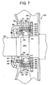
- Figure 7 is a schematic view of a portion of an electric motor 300 that includes a motor housing (not shown).
- the motor housing includes a shell (not shown) with first and second ends (not shown), a first end shield 302 mounted to the first shell end and including an opening (not shown) therethrough, and a second end shield (not shown) mounted to the second shell end and including an opening (not shown) therethrough.
- Motor 300 also includes a rotor (not shown) including a rotor core (not shown) with a bore (not shown) extending through the core and a shaft 304 extending through the bore.
- End shield 302 includes a bearing system 306 that, in one embodiment, is positioned at least partially within first end shield 302.
- Bearing system 306 also can be mounted to the outboard side of end shield 302.
- Bearing system 306 includes a bearing housing 308 and a bearing 310 positioned within bearing housing 308.
- Bearing housing 308 includes a sleeve 312 and a bearing cap 314.
- Sleeve 312 includes a lip 316 and a bearing bore 318 that includes a bore surface 320 having a pair of relief cuts 322, 324.
- Bearing cap 314 includes a lip 326 and an opening 328. Lip 326 cooperates with sleeve 312 to keep sleeve 312 properly positioned with respect to shaft 304.
- Bearing housing 308, bearing sleeve 312, and bearing cap 314 can be formed individually.
- bearing housing 308, bearing sleeve 312, and bearing cap 314 can be formed unitarily with end shield 302.
- bearing cap 314, bearing sleeve 312, and bearing housing 302 can be formed unitarily and then positioned onto end shield 302.
- Bearing 310 includes an outer race 332, an inner race 334, and at least one ball 336. Alternatively, bearing 310 could include at least one roller.
- Bearing housing 308 further includes an opening 338, an adjust screw 340, and a spring 342 that contacts outer race 332 and provides an axial preload force A on ball 336.
- Adjust screw 340 is positioned, at least partially, within opening 338, and extends through opening 338.
- bearing system 306 includes four preload adjust screws 340. Of course, bearing system 306 could include as few as one screw 340 or more than four screws 340.
- a preload adjust plate 344 is placed between adjust screw 340 and spring 342. Preload adjust plate 344 assists in establishing a stable contact between adjust screw 340 and spring 342.
- Adjust plate 344 includes a lip 346, that, in one embodiment, extends substantially radially away from shaft 304.
- bearing sleeve lip 316 extends substantially radially toward shaft 304.
- Adjust plate lip 346 is positioned on an inboard side of bearing sleeve lip 316 and cooperates with bearing sleeve lip 316 to assist in preventing adjust plate 344 from falling out of bearing system 306 even when adjust screw 340 is removed from opening 338.
- Adjust screw 340 can be manipulated to adjust the force preload spring 338 imparts to bearing 310.
- adjust screw 340 is turned to provide more tension to spring 342.
- Spring 342 then contacts outer race 332 and moves outer race 332 into contact with ball 336. Ball 336 is then moved into contact with inner race 334.
- Motor 300 further includes a stator (not shown) that is mounted in the motor housing and a bore extending through the stator.
- Substantially straight rotor shaft 304 is rotatably mounted in the motor housing and extends through the stator bore, the rotor bore, end shield 302, and bearing system 306.
- Bearing 310 rotatably supports shaft 304.
- Outer race 332 includes a first edge 348, a second edge 350. and a connecting portion 352.
- First edge 348 intersects connecting portion 352 at a first corner 354, and second edge 350 intersects connecting portion 352 at a second corner 356.
- bore surface 320 includes an intermediate portion 358.
- Outer race 332 is positioned so that intermediate portion 358 contacts outer race connecting portion 352, first edge 348 is positioned adjacent relief cut 322, and second edge 350 is positioned adjacent second relief cut 324.
- first relief cut 322 includes a first side 360, a second side 362, and a bottom surface 364, and second relief cut 324 includes a first side 366, a second side 368, and a bottom surface 370.
- First edge 348 and first corner 354 are positioned between first side 360 and second side 362 of first relief cut 322.
- second edge 350 and second corner 354 are positioned between first side 366 and second side 368 of second relief cut 324. This positioning prevents edges 322, 324 from contacting bore surface 320.
- screw 340 In operation, screw 340 extends through opening 338 and contacts preload plate 344. Preload plate 344 then compresses spring 342. Compressed spring 342 increases the preload force applied to outer race 332. The force from spring 342 then causes outer race 332 to move axially along shaft 304. This axial movement causes outer race 332 to slide along bore surface 320 which results in a polishing of bore surface 320. Since edges 348, 350 are not in contact with bore surface 320, they do not increase the friction force caused by movement of outer race 332 along bore surface 320.
- Bearing system 306 is assembled by first positioning bearing 310 onto rotor shaft 302. Preload adjust plate 344, preload screw 340, and preload spring 342 are positioned onto end shield 302. Rotor shaft 302 is then positioned through the opening on end shield 302 until bearing 310 is adjacent an outboard side of end shield 302. Preload spring 342 is then adjusted until spring 342 contacts bearing 310 and provides the desired axial preload force A to bearing 310.
- preload adjust screw 340 is positioned to extend through bearing housing opening 338.
- Preload adjust screw 340 is then turned until the desired axial preload force A is applied to spring 342.
- Axial preload force A is transmitted from screw 340 to spring 342 and then to outer race 332.
- Axial preload force A is then transmitted to ball 336 and then to inner race 334.
- the rotor is further positioned to align first relief cut 322 with first edge 348, and second relief cut 324 with second edge 350.
- FIG 8 is a schematic view of an electric motor 400 including another embodiment of a bearing system 402, described below in more detail.
- Motor 400 includes a housing 404 having a shell 406 with a first end 408 and a second end 410.
- a first end shield 412 is mounted to first end 408 and a second end shield 414 is mounted to second end 410.
- a first opening 416 extends through first end shield 412 and a second opening 418 extends through second end shield 414.
- Motor 400 also includes a stator 420 having a bore 422 therethrough.
- Stator is connected to housing 404.
- a rotor 424 extends through stator bore 422 and includes a rotor core 426.
- a rotor bore 428 extends through rotor core 426.
- a rotor shaft 430 is rotatably mounted in housing 404 and extends through rotor bore 428 and through first opening 416 and second opening 418 in end shields 412, 414 respectively.
- Figure 9 is a partial schematic view of bearing system 402, end shield 412, and rotor shaft 430.
- bearing system 402 is positioned, at least partially, within end shield 412.
- bearing system 402 could be mounted to an outboard side of end shield 412.
- Bearing system 402 includes a sleeve 434 and a bearing cap 436 forming a cavity 438.
- a bearing 440 is positioned within cavity 438 formed by sleeve 434 and bearing cap 436.
- Sleeve 434 includes a shoulder, or step, 442 and a bearing bore 444 that includes a bore surface 446 having a pair of relief cuts 448, 450.
- Bearing cap 436 includes a lip 452 that cooperates with sleeve 434 to maintain sleeve 434 properly positioned with respect to shaft 430.
- Bearing sleeve 434 and bearing cap 436 can be fabricated individually.
- bearing sleeve 434 and bearing cap 436 are formed unitarily with end shield 412.
- bearing cap 436 and bearing sleeve 434 can be formed unitarily, and then positioned onto end shield 412.
- Bearing 440 includes and outer race (not shown), an inner race (not shown), and at least one ball (not shown). Alternatively, bearing 440 could include at least one roller.
- Bearing system 402 further includes at least one spring 454 that contacts the outer race of bearing 440.
- Spring 454 provides an axial preload force A on the ball.
- Spring 454 is also in contact with shoulder 442 of sleeve 434 that provides axial support for spring 454.
- Spring 454 is compressed between shoulder 442 and bearing 440 which causes pre-load axial force A to be exerted on bearing 440.
- spring 454 is a wave spring, or a bearing preload spring washer.
- spring 454 could be any type of spring that fits within the space between shoulder 442 and bearing 440, such as a coil spring.
- Bearing 440 includes a first edge 456, a second edge 458, and a connecting portion 460.
- First edge 456 intersects connecting portion 460 at a first corner 462, and second edge 458 intersects connecting portion 460 at a second corner 464.
- bore surface 446 includes an intermediate portion 466.
- Bearing 440 is positioned so that intermediate portion 466 contacts bearing connecting portion 460.
- first edge 456 is positioned adjacent first relief cut 448
- second edge 458 is positioned adjacent second relief cut 450.
- first relief cut 448 includes a first side 468, a second side 470, and a bottom surface 472.
- Second relief cut 450 includes a first side 474, a second side 476, and a bottom surface 478.
- First edge 456 and first corner 462 are positioned between first side 468 and second side 470 of first relief cut 448.
- second edge 458 and second corner 464 are positioned between first side 474 and second side 476 of second relief cut 450. This positioning prevents edges 456, 458 from contacting bore surface 446.
- Minimizing bearing noise over the entire operating range includes maintaining a minimum axial preload on the bearing.
- axial preload force A should be set high enough to account for the worst case of sticking and still supply the minimum bearing preload force. At times when the sticking is not present or not at the worst case level, the axial preload force will be higher than necessary.
- eliminating the edge sticking force results in a lower axial preload force over the operating range of the bearing system.
- Lowering the axial preload forces leads to increased bearing life.
- the use of relief cuts reduce the misalignment of bearings due to localized sticking of the bearing on the bore surface.
Landscapes
- Engineering & Computer Science (AREA)
- General Engineering & Computer Science (AREA)
- Mechanical Engineering (AREA)
- Support Of The Bearing (AREA)
Claims (23)
- Lagersystem (306) mit einem Lagergehäuse (308), das eine Öffnung (338) und eine Lagerbohrung aufweist, wobei wenigstens ein Lager (310) dazu eingerichtet ist, eine Welle (304) drehbar zu lagern, wobei das Lager (310) in der Lagerbohrung angeordnet ist und einen Innenraum (334), einen Außenring (332) und wenigstens eine Kugel (336) aufweist, dadurch gekennzeichnet,
dass eine Oberfläche der Lagerbohrung wenigstens eine Entlastungsausnehmung (322) aufweist,
dass der Außenring wenigstens eine erste Kante (348), eine zweite Kante (350) und einen sich zwischen beiden erstreckenden Verbindungsabschnitt (358) aufweist, wobei wenigstens eine der ersten und der zweiten Kante an der wenigstens einen Entlastungsausnehmung (322) angeordnet ist und
Federmittel (342) vorgesehen sind, die dazu eingerichtet sind, auf das Lager (310) eine axiale Vorspannung auszuüben. - Lagersystem nach Anspruch 1, bei dem zu dem axialen Vorspannmittel die Feder (342) gehört, die mit dem Außenring (332) in Berührung steht.
- Lagersystem nach Anspruch 2, bei dem das axiale Vorspannmittel außerdem eine Stellschraube (340) enthält, die sich durch die Gehäuseöffnung (338) hindurch erstreckt.
- Lagersystem nach Anspruch 2, bei dem das Gehäuse (308) außerdem eine Schulter aufweist, wobei die Feder (342) an der Schulter anliegt, so dass die Vorspannfeder (342) bei vollständig montiertem System ausreichend zusammengedrückt wird, um die vorbestimmte Vorspannkraft zu liefern.
- Lagersystem nach Anspruch 3, bei dem das axiale Vorspannmittel außerdem eine Justageplatte (344) enthält, die zwischen der Stellschraube (340) und der Feder (342) angeordnet ist.
- Lagersystem nach Anspruch 1, bei dem die wenigstens eine Entlastungsausnehmung wenigstens eine erste Entlastungsausnehmung (322), eine zweite Entlastungsausnehmung (324) und einen Zwischenabschnitt (358) enthält, wobei die erste Entlastungsausnehmung (322) der ersten Kante (348) benachbart und die zweite Entlastungsausnehmung (324) der zweiten Kante (350) benachbart angeordnet ist.
- Lagersystem nach Anspruch 6, bei dem die erste und die zweite Entlastungsausnehmung (322, 324) jeweils eine erste Seite (360, 366) und eine zweite Seite (362, 368) aufweist, wobei eine erste Kante (348) zwischen der ersten und der zweiten Seite der ersten Entlastungsausnehmung angeordnet ist und wobei die zweite Kante (350) zwischen der ersten und der zweiten Seite der zweiten Entlastungsausnehmung angeordnet ist.
- Lagersystem nach Anspruch 6, bei dem der Außenringverbindungsabschnitt (352) dem Bohrungsflächenmittelabschnitt (358) benachbart angeordnet ist, wobei der Verbindungsabschnitt den Mittelabschnitt berührt.
- Lagersystem nach Anspruch 5, bei dem die Justageplatte (344) eine Lippe (346) aufweist, wobei das Lagergehäuse außerdem aufweist:eine Lagerbuchse mit einer Lippe (316), wobei die Lagerbuchse dem Außenring benachbart angeordnet ist und wobei die Lagerbuchsenlippe (316) mit der Justageplattenlippe (346) zusammenwirkt, um die Justageplatte (344) in dem Gehäuse zu halten undeine Lagerkappe (314) mit einer Lippe, wobei die Lagerkappenlippe (326) mit der Lagerhülse zusammenwirkt, um die Lagerhülse (312) richtig zu positionieren.
- Elektromotoranordnung (300) mit einer Lageranordnung (306) gemäß Anspruch 2, mit einem Motorgehäuse, das eine Schale mit einem ersten und einem zweiten Ende aufweist, mit einem ersten Endschild (302), das an dem ersten Ende der Gehäuseschale angeordnet ist und mit einem zweiten Endschild, das an dem zweiten Ende der Gehäuseschale angeordnet ist, wobei der Rotor einen Rotorkern mit einer Durchgangsbohrung und einer im Wesentlichen geraden Welle (304) aufweist, die sich durch die Rotorkernbohrung erstreckt und mit einem Stator, der in dem Motorgehäuse montiert ist und eine Durchgangsbohrung aufweist, wobei der Rotor in dem Motorgehäuse drehbar gelagert ist und sich durch die Statorbohrung erstreckt, wobei die Welle (304) durch das Lager (310) drehbar gelagert ist.
- Elektromotoranordnung nach Anspruch 10, mit einer Stellschraube (340) zur Justage der Spannung der Feder (342).
- Elektromotoranordnung nach Anspruch 11, bei der das Lagersystem außerdem eine Justageplatte (344) aufweist, die zwischen der Feder (342) und der Stellschraube (340) angeordnet ist.
- Elektromotoranordnung nach Anspruch 10, bei der das Gehäuse außerdem eine die Feder (342) berührende Schulter aufweist, wobei die Schulter dazu eingerichtet ist, die Feder (342) zusammenzudrücken, um die axiale Vorspannung zu erzeugen.
- Elektromotoranordnung nach Anspruch 11, bei der das Lagergehäuse außerdem eine Stellschraubenöffnung aufweist, wobei die Stellschraube (340) wenigstens teilweise in der Stellschraubenöffnung angeordnet ist.
- Elektromotoranordnung nach Anspruch 10, bei der die wenigstens eine Entlastungsausnehmung eine erste Entlastungsausnehmung (322), eine zweite Entlastungsausnehmung (324) und einen Zwischenabschnitt (358) umfasst, wobei der Außenring (332) so angeordnet ist, dass der Zwischenabschnitt den Verbindungsabschnitt berührt, wobei die erste Kante (348) der Entlastungsausnehmung benachbart und die zweite Kante (350) der zweiten Entlastungsausnehmung benachbart angeordnet ist.
- Elektromotoranordnung nach Anspruch 10, bei der die Feder (342) dazu eingerichtet ist, den Außenring (332) der Lageranordnung und die Feder zu bewegen, um die Vorspannung der Lageranordnung einzustellen.
- Verfahren zum Zusammenbau eines Lagersystems (306) für einen Elektromotor (300), wobei der Elektromotor ein Endschild (302) mit einer Wellenöffnung und eine Rotorwelle (304) aufweist, die sich durch die Endschildöffnung hindurch erstreckt, wobei das Lagersystem (306) ein Lagergehäuse mit einer Öffnung und einer Bohrung mit wenigstens einer Entlastungsausnehmung (322), einem Lager (310) mit einem Außenring (332), einem Innenring (334) und wenigstens einer Kugel (336) ausweist, wobei das Lagersystem (306) außerdem eine Vorspannfeder (342) aufweist, wobei das Verfahren die Schritte des Positonierens des Lagers (310) auf der Rotorwelle (304) enthält, gekennzeichnet durch:das Anordnen der Vorspannfeder (342) auf der Endschildanordnung,das Einsetzen des Rotors durch die Endschildöffnung, so dass die Lageranordnung (306) der Außenseite des Endschilds benachbart ist undEinstellen der Vorspannfeder (342), so dass sie das Lager berührt.
- Verfahren nach Anspruch 17, wobei das Gehäuse außerdem eine Schulter aufweist, wobei der Schritt des Anordnens der Vorspannfeder (342) den Schritt der Positionierung der Feder gegen die Schulter zur Erzeugung einer Vorspannkraft auf das Lager (310) beinhaltet.
- Verfahren nach Anspruch 17, bei dem das Lagersystem (306) außerdem eine Stellschraube (340) und eine Justageplatte (344) aufweist, wobei der Schritt des Anordnens der Vorspannfeder (342) außerdem den Schritt der Positionierung der Justageschraube und der Justageplatte auf der Endschildanordnung beinhaltet.
- Verfahren gemäß Anspruch 17, wobei der Schritt des Einstellens der axialen Vorspannung die Schritte beinhaltet, dass die Vorspannungseinstellschraube (342) so positioniert wird, dass sie sich durch die Lagergehäuseöffnung erstreckt und dass die Vorspanneinstellschraube (342) so eingestellt wird, dass sie eine Vorspannkraft auf die Feder ausübt, die dann auf den äußeren Ring (332) des Lagers (310) übertragen wird.
- Verfahren gemäß Anspruch 20, bei dem der Schritt des Justierens der Vorspannungseinstellschraube (342) den Schritt beinhaltet, dass die Schraube gedreht wird, um die Vorspannkraft auf den Außenring des Lagers (310) zu erhöhen.
- Verfahren gemäß Anspruch 17, bei dem die wenigstens eine Entlastungsausnehmung eine erste Entlastungsausnehmung (322) und eine zweite Entlastungsausnehmung (324) aufweist, wobei der Außenring (332) eine erste Kante und eine zweite Kante aufweist, wobei der Schritt des Positionierens des Rotors durch die Endschildöffnung den Schritt des Positionierens der ersten und der zweiten Kante des Außenrings beinhaltet, so dass sie die erste bzw. die zweite Entlastungsausnehmung überlappen.
- Verfahren nach Anspruch 17, bei dem der Schritt des Einstellens der Vorspannfeder den Schritt der Übertragung der axialen Vorspannkraft auf das Lager (310) beinhaltet, indem der Außenring (332) bewegt wird, um mit dem Lager (310) einen Berührungswinkel festzulegen.
Applications Claiming Priority (3)
| Application Number | Priority Date | Filing Date | Title |
|---|---|---|---|
| US162307 | 1998-09-28 | ||
| US09/162,307 US6123462A (en) | 1998-09-28 | 1998-09-28 | Bearing system having reduced noise and axial preload |
| PCT/US1999/021137 WO2000019119A1 (en) | 1998-09-28 | 1999-09-15 | Bearing systems having reduced noise and axial preload |
Publications (2)
| Publication Number | Publication Date |
|---|---|
| EP1045995A1 EP1045995A1 (de) | 2000-10-25 |
| EP1045995B1 true EP1045995B1 (de) | 2006-01-11 |
Family
ID=22585078
Family Applications (1)
| Application Number | Title | Priority Date | Filing Date |
|---|---|---|---|
| EP99969773A Expired - Lifetime EP1045995B1 (de) | 1998-09-28 | 1999-09-15 | Lagersystem mit geräuschverminderung und axialer vorspannung |
Country Status (7)
| Country | Link |
|---|---|
| US (2) | US6123462A (de) |
| EP (1) | EP1045995B1 (de) |
| KR (1) | KR100699633B1 (de) |
| CN (1) | CN1107814C (de) |
| DE (1) | DE69929473T2 (de) |
| DK (1) | DK1045995T3 (de) |
| WO (1) | WO2000019119A1 (de) |
Families Citing this family (21)
| Publication number | Priority date | Publication date | Assignee | Title |
|---|---|---|---|---|
| US6409390B1 (en) * | 2000-10-31 | 2002-06-25 | Itt Manufacturing Enterprises, Inc. | Compact, precision duplex bearing mount for high vibration environments |
| US6520684B2 (en) * | 2001-03-29 | 2003-02-18 | International Engine Intellectual Property Company, L.L.C. | Bearing retention system |
| US6868749B2 (en) * | 2001-11-28 | 2005-03-22 | Delphi Technologies, Inc. | Bearing configuration and method for reducing noise in a bearing |
| DE50310608D1 (de) * | 2002-02-28 | 2008-11-20 | Luk Lamellen & Kupplungsbau | Entkopplungsvorrichtung für eine lagerung einer welle an einem grundkörper sowie radialwellfeder |
| US7021831B2 (en) * | 2003-10-02 | 2006-04-04 | Torrington Research Co. | Zero radial and axial clearance bearing assembly |
| US7153031B2 (en) * | 2004-05-27 | 2006-12-26 | Emerson Electric Co. | Bearing assembly with anti-slip spring |
| BRPI0419157A (pt) * | 2004-10-28 | 2007-12-11 | Volvo Lastvagnar Ab | unidade turbocharger com suportes para um eixo de rotor |
| US20070267263A1 (en) * | 2006-05-19 | 2007-11-22 | Jack Eric Pederson | Overrunning clutch |
| JP2008298284A (ja) * | 2007-05-01 | 2008-12-11 | Jtekt Corp | ターボチャージャ用軸受装置 |
| US20090034896A1 (en) * | 2007-08-03 | 2009-02-05 | Kenneth Lee Fisher | Bearing retainer |
| DE102008054848A1 (de) * | 2008-12-18 | 2010-07-01 | Robert Bosch Gmbh | Maschine mit Lagervorrichtung |
| US8851227B2 (en) | 2009-01-23 | 2014-10-07 | Aktiebolaget Skf | Bearing assembly for a power steering mechanism |
| US9046130B2 (en) | 2009-12-29 | 2015-06-02 | Rolls-Royce Corporation | Gas turbine engine and high speed rolling element bearing |
| DE102010003233A1 (de) * | 2010-03-25 | 2011-09-29 | Zf Lenksysteme Gmbh | Servolenkung |
| CA2817759C (en) | 2010-11-19 | 2017-09-26 | Gregg Jones | Turbocharger operating system and method for an internal combustion engine |
| US9103375B2 (en) * | 2012-12-14 | 2015-08-11 | Aktiebolaget Skf | Cartridge bearing assembly |
| CN106151266B (zh) * | 2015-03-27 | 2019-09-03 | 长城汽车股份有限公司 | 一种驱动轴轴承与分动器轴承套的配合组件 |
| TWI622717B (zh) * | 2016-11-23 | 2018-05-01 | 東元電機股份有限公司 | 具有夾合式限位件之軸承及其組裝方法 |
| US11021994B2 (en) * | 2019-11-01 | 2021-06-01 | Pratt & Whitney Canada Corp. | Flanged integral piston bearing |
| DE102023115937A1 (de) * | 2022-06-27 | 2023-12-28 | Mabuchi Motor Co., Ltd. | Haltestruktur für ein kugellager und gebläsemotor |
| FR3154449A1 (fr) * | 2023-10-20 | 2025-04-25 | Safran Aircraft Engines | procédé de montage d’un rotor entre deux paliers |
Family Cites Families (51)
| Publication number | Priority date | Publication date | Assignee | Title |
|---|---|---|---|---|
| US675975A (en) * | 1900-12-06 | 1901-06-11 | August Riebe | Axle-bearing. |
| US1778258A (en) * | 1923-07-09 | 1930-10-14 | Nash Engineering Co | Journal box |
| US2711356A (en) * | 1952-06-30 | 1955-06-21 | Willis B Ensinger | Bearing construction for high speed rotors |
| US2858174A (en) * | 1956-02-17 | 1958-10-28 | John E Mitchell Company Inc | Bearing mounting |
| BE560155A (de) * | 1956-08-20 | 1900-01-01 | ||
| US3001839A (en) * | 1958-06-02 | 1961-09-26 | Horberg Grinding Ind Inc | Bearing structure |
| US2962912A (en) * | 1958-10-02 | 1960-12-06 | Alfred C Hirschle | Means for minimizing backlash |
| US3214224A (en) * | 1963-04-17 | 1965-10-26 | Trw Inc | Bearing assembly |
| US3738719A (en) * | 1970-08-04 | 1973-06-12 | Snecma | Ball bearing |
| FR2256690A5 (de) * | 1973-12-26 | 1975-07-25 | Glaenzer Spicer Sa | |
| JPS5320611B2 (de) * | 1974-06-05 | 1978-06-28 | ||
| JPS5552091Y2 (de) * | 1976-04-30 | 1980-12-03 | ||
| US4211454A (en) * | 1978-10-16 | 1980-07-08 | Bryant Grinder Corporation | Antifriction bearing support |
| DE3004316C2 (de) * | 1980-02-06 | 1983-12-29 | Skf Kugellagerfabriken Gmbh, 8720 Schweinfurt | Lagerung einer Welle eines Maschinenelementes |
| US4519734A (en) * | 1982-06-22 | 1985-05-28 | Ex-Cello-O Corporation | High speed spindle with preloaded bearings |
| US4563099A (en) * | 1983-04-15 | 1986-01-07 | Skf Kugellagerfabriken Gmbh | Rolling bearing unit |
| JPS604621A (ja) * | 1983-06-21 | 1985-01-11 | Yoshitsuka Seiki:Kk | スピンドル支持装置 |
| SE438894B (sv) * | 1983-09-23 | 1985-05-13 | Alfa Laval Separation Ab | Lageranordning for en spindel |
| US4523864A (en) * | 1984-04-27 | 1985-06-18 | United Technologies Corporation | Tandem bearing construction |
| JPS60178623U (ja) * | 1984-05-10 | 1985-11-27 | 日本精工株式会社 | 軸受の取付装置 |
| US4551032A (en) * | 1984-07-16 | 1985-11-05 | The Cross Company | Mechanism for pre-loading bearings |
| IT8429049V0 (it) * | 1984-11-30 | 1984-11-30 | Italtractor Mecc Itm Spa Soc | Rullo lubrificato perfezionato, per cingoli di mezzi cingolati, in particolare rullo superiore, con albero fissato a sbalzo e cuscinetti a rotolamento |
| US4555190A (en) * | 1985-01-17 | 1985-11-26 | General Motors Corporation | Clutch release bearing assembly |
| US4626111A (en) * | 1985-07-25 | 1986-12-02 | Farrel Corporation | Self-compensating anti-friction bearing clearance device |
| US4641558A (en) * | 1985-08-16 | 1987-02-10 | B & H Manufacturing Company | Rotatable shaft assembly |
| DE8533642U1 (de) * | 1985-11-29 | 1986-01-16 | SKF GmbH, 8720 Schweinfurt | Anordnung zur Anstellung eines Wälzlagers |
| JPS62124920U (de) * | 1986-01-29 | 1987-08-08 | ||
| FR2594189B1 (fr) * | 1986-02-07 | 1988-05-27 | Nadella | Roulement a billes a precontrainte et procede et outil pour sa fabrication |
| US4699528A (en) * | 1986-04-21 | 1987-10-13 | Zephyr Manufacturing Company | Rotary assembly having self-positioning bearing, and method |
| US4741091A (en) * | 1986-08-12 | 1988-05-03 | Dayco Products-Eaglemotive, Inc. | Clutch for a cooling fan of a motor vehicle and method of making the same |
| US4726696A (en) * | 1986-10-14 | 1988-02-23 | The Torrington Company | Molded rubber seal for bearing and stamping assembly |
| US4798523A (en) * | 1986-12-19 | 1989-01-17 | Allied-Signal Inc. | Turbocharger bearing and lubrication system |
| SE453318B (sv) * | 1987-02-18 | 1988-01-25 | Svenska Rotor Maskiner Ab | Rotormaskin med en axialkraftbalanseringsanordning |
| FR2625273A1 (fr) * | 1987-12-23 | 1989-06-30 | Europ Propulsion | Dispositif de montage de paliers a roulements |
| US4808013A (en) * | 1988-01-11 | 1989-02-28 | Avco Corporation | Bearing assembly |
| JPH0826898B2 (ja) * | 1989-03-30 | 1996-03-21 | キタムラ機械株式会社 | 軸受用予圧装置 |
| US4966474A (en) * | 1989-06-01 | 1990-10-30 | Ingersoll-Rand Company | Lockable nut for axial adjustment |
| US5030016A (en) * | 1990-07-11 | 1991-07-09 | Societe Nationale Industrielle Et Aerospatiale | Process and apparatus for the release of a prestress initially applied to a mechanism such as a bearing on board a space vehicle |
| US5046870A (en) * | 1990-08-02 | 1991-09-10 | General Motors Corporation | End play and preload adjusting assembly for tapered bearings |
| US5051005A (en) * | 1990-08-17 | 1991-09-24 | The Torrington Company | Variable preload bearing apparatus |
| DE4028273A1 (de) * | 1990-09-06 | 1992-03-12 | Kugelfischer G Schaefer & Co | Lagerung, insbesondere fuer plattenspeicherspindeln |
| DE4032953A1 (de) * | 1990-10-17 | 1992-04-30 | Kugelfischer G Schaefer & Co | Zweireihiges schraegwaelzlager |
| DE59202159D1 (de) * | 1991-12-12 | 1995-06-14 | Barmag Barmer Maschf | Friktionsfalschdrallaggregat. |
| US5316393A (en) * | 1992-09-30 | 1994-05-31 | The United States Of America As Represented By The Secretary Of The Navy | Duplex rolling element bearing mounting for ensuring preload control |
| US5433536A (en) * | 1993-06-18 | 1995-07-18 | Aktiebolaget Skf | Thrust bearings |
| US5547291A (en) * | 1993-09-29 | 1996-08-20 | Nsk, Ltd. | Preloaded rolling bearing units |
| JPH0880007A (ja) * | 1994-09-01 | 1996-03-22 | Fanuc Ltd | 電動モータの軸受支持構造 |
| US5494359A (en) * | 1995-02-15 | 1996-02-27 | The Anspach Effort, Inc. | High speed tool shaft bearing system |
| DE29504068U1 (de) * | 1995-03-09 | 1995-05-04 | Skf Gmbh | Lageranordnung |
| US5590968A (en) * | 1995-09-18 | 1997-01-07 | Harnischfeger Corporation | Bearing retainer assembly |
| US5690395A (en) * | 1996-05-24 | 1997-11-25 | Hicks; Jimmy L. | Shopping cart wheel assembly with anti-friction bearing and friction bearing |
-
1998
- 1998-09-28 US US09/162,307 patent/US6123462A/en not_active Expired - Lifetime
-
1999
- 1999-09-15 DK DK99969773T patent/DK1045995T3/da active
- 1999-09-15 CN CN99801698A patent/CN1107814C/zh not_active Expired - Fee Related
- 1999-09-15 KR KR1020007005683A patent/KR100699633B1/ko not_active Expired - Fee Related
- 1999-09-15 EP EP99969773A patent/EP1045995B1/de not_active Expired - Lifetime
- 1999-09-15 DE DE69929473T patent/DE69929473T2/de not_active Expired - Lifetime
- 1999-09-15 WO PCT/US1999/021137 patent/WO2000019119A1/en not_active Ceased
-
2000
- 2000-08-29 US US09/650,914 patent/US6394658B1/en not_active Expired - Lifetime
Also Published As
| Publication number | Publication date |
|---|---|
| CN1286743A (zh) | 2001-03-07 |
| KR100699633B1 (ko) | 2007-03-23 |
| DK1045995T3 (da) | 2006-05-08 |
| WO2000019119A1 (en) | 2000-04-06 |
| CN1107814C (zh) | 2003-05-07 |
| US6123462A (en) | 2000-09-26 |
| DE69929473T2 (de) | 2006-09-07 |
| DE69929473D1 (de) | 2006-04-06 |
| US6394658B1 (en) | 2002-05-28 |
| EP1045995A1 (de) | 2000-10-25 |
| KR20010032442A (ko) | 2001-04-25 |
Similar Documents
| Publication | Publication Date | Title |
|---|---|---|
| EP1045995B1 (de) | Lagersystem mit geräuschverminderung und axialer vorspannung | |
| KR100619164B1 (ko) | 동압형 베어링 및 동압형 베어링 유닛 | |
| US5316393A (en) | Duplex rolling element bearing mounting for ensuring preload control | |
| US7594761B2 (en) | Cylindrical roller bearing and cage for cylindrical roller bearings | |
| EP1300600B1 (de) | Lageranordnung und Verfahren | |
| EP1347185B1 (de) | Zylinderrollenlager | |
| EP0746698B1 (de) | Axiallageranordnung | |
| EP1529596B1 (de) | Drehtisch mit zwei Lagern | |
| US5129738A (en) | Bearing device | |
| JP3222998B2 (ja) | ボールスプライン | |
| US20020110298A1 (en) | Ball bearing | |
| JP2008057657A (ja) | Nc自動旋盤の主軸軸受構造 | |
| US5921685A (en) | Tapered roller bearing for vehicle | |
| JPH0554565B2 (de) | ||
| US20120056501A1 (en) | Rotor shaft and ac generator for vehicle | |
| JP2000304054A (ja) | 円すいころ軸受 | |
| JPH11347886A (ja) | 工作機械の主軸装置 | |
| JPH10225802A (ja) | 工作機械の主軸装置 | |
| US4482338A (en) | Torque transmitting bearing assembly for members adapted for a relative longitudinal movement and method of assembly thereof | |
| JPH02279203A (ja) | 予圧可変式スピンドルユニット | |
| JP2008030132A (ja) | Nc自動旋盤の主軸軸受構造 | |
| JPH0751904A (ja) | スピンドル軸受の予圧調整装置 | |
| SU1183737A1 (ru) | Радиальный подшипник скольжени | |
| KR950001808B1 (ko) | 베어링내경가공장치 | |
| JPH10315059A (ja) | スラスト軸受部品の製造方法 |
Legal Events
| Date | Code | Title | Description |
|---|---|---|---|
| PUAI | Public reference made under article 153(3) epc to a published international application that has entered the european phase |
Free format text: ORIGINAL CODE: 0009012 |
|
| AK | Designated contracting states |
Kind code of ref document: A1 Designated state(s): AT BE CH CY DE DK ES FI FR GB GR IE IT LI LU MC NL PT SE |
|
| 17P | Request for examination filed |
Effective date: 20001006 |
|
| 17Q | First examination report despatched |
Effective date: 20040122 |
|
| RBV | Designated contracting states (corrected) |
Designated state(s): DE DK GB IT |
|
| GRAP | Despatch of communication of intention to grant a patent |
Free format text: ORIGINAL CODE: EPIDOSNIGR1 |
|
| GRAS | Grant fee paid |
Free format text: ORIGINAL CODE: EPIDOSNIGR3 |
|
| GRAA | (expected) grant |
Free format text: ORIGINAL CODE: 0009210 |
|
| AK | Designated contracting states |
Kind code of ref document: B1 Designated state(s): DE DK GB IT |
|
| REF | Corresponds to: |
Ref document number: 69929473 Country of ref document: DE Date of ref document: 20060406 Kind code of ref document: P |
|
| REG | Reference to a national code |
Ref country code: DK Ref legal event code: T3 |
|
| PLBE | No opposition filed within time limit |
Free format text: ORIGINAL CODE: 0009261 |
|
| STAA | Information on the status of an ep patent application or granted ep patent |
Free format text: STATUS: NO OPPOSITION FILED WITHIN TIME LIMIT |
|
| 26N | No opposition filed |
Effective date: 20061012 |
|
| PGFP | Annual fee paid to national office [announced via postgrant information from national office to epo] |
Ref country code: DE Payment date: 20130927 Year of fee payment: 15 Ref country code: DK Payment date: 20130925 Year of fee payment: 15 |
|
| PGFP | Annual fee paid to national office [announced via postgrant information from national office to epo] |
Ref country code: GB Payment date: 20130927 Year of fee payment: 15 |
|
| PGFP | Annual fee paid to national office [announced via postgrant information from national office to epo] |
Ref country code: IT Payment date: 20140924 Year of fee payment: 16 |
|
| REG | Reference to a national code |
Ref country code: DE Ref legal event code: R119 Ref document number: 69929473 Country of ref document: DE |
|
| REG | Reference to a national code |
Ref country code: DK Ref legal event code: EBP Effective date: 20140930 |
|
| GBPC | Gb: european patent ceased through non-payment of renewal fee |
Effective date: 20140915 |
|
| REG | Reference to a national code |
Ref country code: DE Ref legal event code: R119 Ref document number: 69929473 Country of ref document: DE Effective date: 20150401 |
|
| PG25 | Lapsed in a contracting state [announced via postgrant information from national office to epo] |
Ref country code: GB Free format text: LAPSE BECAUSE OF NON-PAYMENT OF DUE FEES Effective date: 20140915 Ref country code: DE Free format text: LAPSE BECAUSE OF NON-PAYMENT OF DUE FEES Effective date: 20150401 |
|
| PG25 | Lapsed in a contracting state [announced via postgrant information from national office to epo] |
Ref country code: DK Free format text: LAPSE BECAUSE OF NON-PAYMENT OF DUE FEES Effective date: 20140930 |
|
| PG25 | Lapsed in a contracting state [announced via postgrant information from national office to epo] |
Ref country code: IT Free format text: LAPSE BECAUSE OF NON-PAYMENT OF DUE FEES Effective date: 20150915 |