EP1045297A1 - Coaxial lever escapement - Google Patents
Coaxial lever escapement Download PDFInfo
- Publication number
- EP1045297A1 EP1045297A1 EP99107164A EP99107164A EP1045297A1 EP 1045297 A1 EP1045297 A1 EP 1045297A1 EP 99107164 A EP99107164 A EP 99107164A EP 99107164 A EP99107164 A EP 99107164A EP 1045297 A1 EP1045297 A1 EP 1045297A1
- Authority
- EP
- European Patent Office
- Prior art keywords
- anchor
- wheel
- exhaust
- teeth
- fork
- Prior art date
- Legal status (The legal status is an assumption and is not a legal conclusion. Google has not performed a legal analysis and makes no representation as to the accuracy of the status listed.)
- Granted
Links
Images


Classifications
-
- G—PHYSICS
- G04—HOROLOGY
- G04B—MECHANICALLY-DRIVEN CLOCKS OR WATCHES; MECHANICAL PARTS OF CLOCKS OR WATCHES IN GENERAL; TIME PIECES USING THE POSITION OF THE SUN, MOON OR STARS
- G04B15/00—Escapements
- G04B15/14—Component parts or constructional details, e.g. construction of the lever or the escape wheel
-
- G—PHYSICS
- G04—HOROLOGY
- G04B—MECHANICALLY-DRIVEN CLOCKS OR WATCHES; MECHANICAL PARTS OF CLOCKS OR WATCHES IN GENERAL; TIME PIECES USING THE POSITION OF THE SUN, MOON OR STARS
- G04B15/00—Escapements
- G04B15/06—Free escapements
- G04B15/08—Lever escapements
Definitions
- the present invention relates to a one-piece coaxial exhaust timepiece comprising first and second escapement wheels mounted coaxially the first on the second, an intermediate wheel meshing with the first escape wheel, a balance plate carrying a plateau pin and a pulse paddle arranged for cooperate with the teeth carried by the second escape wheel, and a anchor located at the first escape wheel, this anchor comprising a fork cooperating with the plate pin, a pallet impulse arranged to cooperate with the first wheel teeth exhaust, and first and second rest paddles arranged to cooperate with the teeth of the second escape wheel.
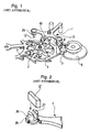
- FIGS. 1 and 2 of the present description which represents the prior art.
- the height of wheels 2 and 3 of the coaxial exhaust can be considered a disadvantage for using this escapement in watches extra-flat, G. Daniels imagined an execution without an exhaust gear as was also the case with the execution set out in the patent cited more high.
- the wheel 2 provides a double function: that of the exhaust pinion meshing with the intermediate wheel 4 and that of the escape wheel cooperating with the pallet 10 of the anchor 1, which saves an exhaust pinion which would overcome the wheels 2 and 3 and would increase the height of the assembly as is the case with the description of the cited patent.
- the functioning of the version improved is similar to that of the cited patent.
- the impulse to the plate 5 of the balance wheel is delivered by the wheel exhaust 3 via pallet 7 of plate 5, while the pulse by via the anchor 1 'is given by the escape wheel 2 via the pallet 10 and fork 9 of anchor 1 '.
- the wheel 3 is blocked by one of the rest pallets 12 'or 13' of the anchor 1 '.
- each of the first and second rest pallets is made of a monobloc stone engaged in a groove made in the anchor, said part projecting beyond one of the planar faces of the anchor and having a proper height to bring it to the level where the second wheel moves exhaust to cooperate with the teeth of said second wheel.
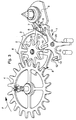
- Figures 3 and 4 show in perspective, respectively seen from above and below the coaxial escapement with which the anchor 1 is associated according to the invention.
- the coaxial exhaust includes a first escape wheel 2 mounted coaxially on a second exhaust wheel 3, of which it is integral.
- An intermediate wheel 4 which may be the last of the finishing train driven by the barrel, turns in the direction of arrow F and transmits the driving force to the first wheel 2 exhaust with which it meshes.
- Figures 3 and 4 show a platform 5 of the pendulum to which the conventional oscillator formed of the pendulum is linked and hairspring (not shown).
- the plate 5 carries a pin 6 of the plate and a pulse palette 7. This pallet 7 is arranged to cooperate with the teeth 8 of the second escape wheel 3.
- the anchor 1 is located at level of the first escape wheel 2.
- the anchor 1 comprises a fork 9 which cooperates with the pin 6 of the plate 5.
- the anchor comprises another pulse palette 10 arranged to cooperate with the teeth 11 of the first escape wheel 2.
- the anchor finally comprises first 12 and second 13 rest paddles arranged to cooperate with the teeth 8 of the second escape wheel 3.
- the anchor 1 according to the invention is remarkable in that each of the first 12 and second 13 pallets rest is made of a monobloc stone engaged in a groove 14 practiced in the thickness of the anchor 1, which distinguishes it from the prior art shown in Figure 2 where the pallet 12 'is engaged in a groove 27 practiced in a tenon 26 itself introduced into the anchor 1 '.
- the stones 12 and 13 project beyond one of the planar faces of the anchor 1, in this case the face 15, and have a height such that they extend to the level where the second escape wheel 3 evolves to cooperate with the teeth 8 of said second wheel.
- stones 12 and 13 are directly linked to anchor 1 without intermediate device.
- Figure 5 is an enlarged plan view of the end portion of the anchor 1 which contains the fork 9 and FIG. 6 an enlargement of the zone VI of figure 5.
- FIG. 5 shows the fork 9 provided with its horns, the pin 6 of tray introduced between the horns, and a dart 30, the latter also being shown in Figure 3.
- the inner sections 16 and 17 of the fork 9 are rectilinear - this which is commonly the case - and not parallel - which is new.
- FIG. 5 shows that the distance d separating the internal panels 16 and 17 from the fork 9 (sides drawn in solid lines) increases gradually as as we approach the bottom 18 of the fork. This so-called provision asymmetrical brings an advantage which we will explain now.
- FIGS. 5 and 6 also show non-parallel sections 16 and 17, parallel sections 16 'and 17' drawn in dotted lines and which are used in known constructions.
- the anchor 1 receives a pulse in the direction of arrow A
- the anchor 1 receives a pulse in the direction of the same arrow A
- the point of contact 32 is therefore higher on the periphery 33 of the pin 6 than does was the point of contact 31 on the same periphery 33.
- the invention allows to gain the path that separates points 31 and 32 in the process of outlet of pin 6 of fork 9.
- the friction path that exists between the initial contact point 32 and the ankle separation point with the pan 17, at the exit of the said ankle, is therefore shortened by the distance B which separates points 31 and 32.
- it has been observed in the coaxial exhaust a more friction path as long as the existing path on a conventional exhaust. The improvement proposed is therefore all the more justified, although it could also be implemented on said conventional exhaust.
- a second additional improvement consists in lubricating the pivots 20 and 21 of the shaft 19 which carries the anchor 1 (see FIG. 4). This lubrication has always avoided until today for fear of natural deterioration of the oil used. Oil free however i! a fretting phenomenon occurs corrosion "which is wear caused by dry friction on mobiles affected by small movements or vibrations. This results in a production iron oxide tending to seize the mechanism. We discovered however that with the oils known today, very liquid and not thickening, you can safely use them to oil the anchor pivots.
Landscapes
- Physics & Mathematics (AREA)
- General Physics & Mathematics (AREA)
- Table Equipment (AREA)
- Adornments (AREA)
- Micromachines (AREA)
Abstract
Description
La présente invention est relative à un échappement coaxial d'une pièce d'horlogerie comprenant des première et seconde roues d'échappement montées coaxialement la première sur la seconde, une roue intermédiaire engrenant avec la première roue d'échappement, un plateau de balancier portant une cheville de plateau et une palette d'impulsion arrangée pour coopérer avec les dents portées par la seconde roue d'échappement, et une ancre située au niveau de la première roue d'échappement, cette ancre comportant une fourchette coopérant avec la cheville de plateau, une palette d'impulsion arrangée pour coopérer avec les dents de première roue d'échappement, et des première et seconde palettes de repos arrangées pour coopérer avec les dents de la seconde roue d'échappement.The present invention relates to a one-piece coaxial exhaust timepiece comprising first and second escapement wheels mounted coaxially the first on the second, an intermediate wheel meshing with the first escape wheel, a balance plate carrying a plateau pin and a pulse paddle arranged for cooperate with the teeth carried by the second escape wheel, and a anchor located at the first escape wheel, this anchor comprising a fork cooperating with the plate pin, a pallet impulse arranged to cooperate with the first wheel teeth exhaust, and first and second rest paddles arranged to cooperate with the teeth of the second escape wheel.
Le principe de fonctionnement d'un tel échappement a été décrit dans le brevet EP-B-0 018 796 et une amélioration visant à diminuer la hauteur du mécanisme est exposée dans l'ouvrage de G. Daniels intitulé "La Montre: Principes et Méthodes de Fabrication", pages 249 à 252, éditions Scriptar S.A., La Conversion / Lausanne, 1993.The operating principle of such an exhaust has been described in EP-B-0 018 796 and an improvement aimed at reducing the height of the mechanism is exposed in the work of G. Daniels entitled "The Watch: Principles and Methods of Manufacturing ", pages 249 to 252, editions Scriptar S.A., La Conversion / Lausanne, 1993.
Cette exécution améliorée est illustrée par les figures 1 et 2 de la
présente description qui représente l'art antérieur. Comme la hauteur des
roues 2 et 3 de l'échappement coaxial peut être considérée comme un
désavantage pour l'utilisation de cet échappement dans les montres
extraplates, G. Daniels a imaginé une exécution sans pignon d'échappement
comme c'était encore le cas de l'exécution exposée dans le brevet cité plus
haut. Dans cette version améliorée, on voit que la roue 2 assure une double
fonction : celle de pignon d'échappement engrenant avec la roue intermédiaire
4 et celle de la roue d'échappement coopérant avec la palette 10 de l'ancre
1, ce qui fait l'économie d'un pignon d'échappement qui surmonterait les roues
2 et 3 et augmenterait la hauteur de l'ensemble comme c'est le cas de la
description du brevet cité. A part cela le fonctionnement de la version
améliorée est semblable à celle du brevet cité. Comme le montre la présente
figure 1, l'impulsion au plateau 5 du balancier est délivrée par la roue
d'échappement 3 via la palette 7 du plateau 5, alors que l'impulsion par
l'intermédiaire de l'ancre 1' est donnée par la roue d'échappement 2 via la
palette 10 et la fourchette 9 de l'ancre 1'. Une fois l'impulsion réalisée, la roue
3 est bloquée par une des palettes de repos 12' ou 13' de l'ancre 1'. This improved execution is illustrated by FIGS. 1 and 2 of the
present description which represents the prior art. As the height of
L'ouvrage cité plus haut donne des indications sur la manière dont sont
fixées les palettes de repos 12' et 13' sur l'ancre 1'. La façon de s'y prendre
est montrée en figure 2 de la présente description. L'extrémité 25 de l'ancre
1' est pourvue d'un trou dans lequel est introduit un tenon 26. Ce tenon 26
est pourvu à son tour d'une fente 27 dans laquelle on engage la palette de
repos 12'. Cette disposition amène la palette 12 au niveau de la roue 3 avec
laquelle elle travaille et permet en même temps un ajustement complet de la
profondeur de repos.The book cited above gives indications on how are
fixed the rest pallets 12 'and 13' on the anchor 1 '. The way to go about it
is shown in Figure 2 of this description. The
De l'aveu même de l'auteur de l'ouvrage cité ci-dessus, la confection de l'échappement coaxial est difficile et exige des tolérances serrées. Selon cet auteur, l'échappement coaxial est plus complexe que l'échappement à ancre classique et des difficultés de construction peuvent être un stimulant incitant les fabricants à innover de telle sorte que ces difficultés soient évitées. Les difficultés citées expliquent d'ailleurs en partie pourquoi l'échappement coaxial n'équipe actuellement que quelques pièces d'horlogerie fabriquées et ajustées manuellement à grands frais. Si l'on veut donner une chance d'extension à ce type d'échappement, il faut chercher à le réaliser de telle sorte qu'il puisse être fabriqué industriellement et en séries.By the very admission of the author of the work cited above, the making of coaxial exhaust is difficult and requires tight tolerances. According to this author, coaxial escapement is more complex than anchor escapement classic and construction difficulties can be a stimulating incentive manufacturers to innovate so that these difficulties are avoided. The difficulties cited explain in part why the coaxial escapement currently only equips a few timepieces manufactured and adjusted manually at great expense. If we want to give a chance of extension to this type of exhaust, you have to try to make it so that it can be manufactured industrially and in series.
Ainsi en est-il de l'ancre de l'échappement décrit ci-dessus qui présente
au moins un défaut à savoir la fixation des palettes de repos 12' et 13'. En
effet, comme on l'a vu à propos de la figure 2, la palette n'est pas fixée
directement sur l'ancre mais par l'intermédiaire d'un tenon 26 dont on
pourrait se passer, d'abord parce que c'est une pièce supplémentaire, ensuite
parce qu'il nécessite d'ajuster l'angle de repos, ce qui est fastidieux.So it is with the anchor of the exhaust described above which presents
at least one defect, namely the fixing of the rest pallets 12 'and 13'. In
effect, as we saw about figure 2, the pallet is not fixed
directly on the anchor but via a
Ainsi pour pallier le défaut cité ci-dessus, la présente invention est innovative en ce que chacune des première et seconde palettes de repos est faite d'une pierre monobloc engagée dans une rainure pratiquée dans l'ancre, ladite pièce dépassant une des faces planes de l'ancre et présentant une hauteur propre à l'amener au niveau où évolue la seconde roue d'échappement pour coopérer avec les dents de ladite seconde roue.Thus, to overcome the above-mentioned defect, the present invention is innovative in that each of the first and second rest pallets is made of a monobloc stone engaged in a groove made in the anchor, said part projecting beyond one of the planar faces of the anchor and having a proper height to bring it to the level where the second wheel moves exhaust to cooperate with the teeth of said second wheel.
D'autres innovations que celle citée ci-dessus sont encore apportées à l'ancre en question et seront décrites ci-après.Other innovations than that mentioned above are also made to the anchor in question and will be described below.
L'invention va être décrite maintenant en détail en s'appuyant sur la description qui va suivre, description illustrée par les dessins annexés donnés à titre d'exemple et parmi lesquels:
- la figure 1 est une vue en perspective d'un échappement coaxial extraplat selon l'art antérieur,
- la figure 2 est un détail montrant la fixation d'une palette de repos sur l'ancre selon l'art antérieur,
- la figure 3 est une vue en perspective de dessus d'un échappement coaxial réalisé selon l'invention,
- la figure 4 est une vue en perspective de dessous de l'échappement coaxial de la figure 3,
- la figure 5 est une vue en plan d'une partie de l'ancre de l'échappement des figures 3 et 4 montrant la fourchette dans laquelle la cheville est introduite, et
- la figure 6 est un agrandissement de la zone VI montrée en figure 5.
- FIG. 1 is a perspective view of an extra flat coaxial exhaust according to the prior art,
- FIG. 2 is a detail showing the attachment of a rest pallet to the anchor according to the prior art,
- FIG. 3 is a perspective view from above of a coaxial exhaust produced according to the invention,
- FIG. 4 is a perspective view from below of the coaxial exhaust of FIG. 3,
- FIG. 5 is a plan view of part of the anchor of the exhaust from FIGS. 3 and 4 showing the fork into which the pin is introduced, and
- FIG. 6 is an enlargement of zone VI shown in FIG. 5.
Les figures 3 et 4 montrent en perspective, respectivement vu de
dessus et de dessous l'échappement coaxial auquel est associée l'ancre 1
selon l'invention. Si l'on considère la figure 3, l'échappement coaxial comprend
une première roue 2 d'échappement montée coaxialement sur une seconde
roue 3 d'échappement, dont elle est solidaire. Une roue intermédiaire 4, qui
peut être la dernière du train de finissage entraíné par le barillet, tourne dans
le sens de la flèche F et transmet la force motrice à la première roue 2
d'échappement avec laquelle elle engrène. Les figures 3 et 4 montrent un
plateau 5 du balancier auquel est lié l'oscillateur classique formé du balancier
et du spiral (non représentés). Le plateau 5 porte une cheville 6 de plateau et
une palette 7 d'impulsion. Cette palette 7 est arrangée pour coopérer avec
les dents 8 de la seconde roue d'échappement 3. L'ancre 1 est située au
niveau de la première roue d'échappement 2. L'ancre 1 comporte une
fourchette 9 qui coopère avec la cheville 6 du plateau 5. L'ancre comporte
encore une palette d'impulsion 10 arrangée pour coopérer avec les dents 11
de la première roue d'échappement 2. L'ancre comporte enfin des première
12 et seconde 13 palettes de repos arrangées pour coopérer avec les dents
8 de la seconde roue d'échappement 3.Figures 3 and 4 show in perspective, respectively seen from
above and below the coaxial escapement with which the
Comme on le voit bien sur la figure 4, l'ancre 1 selon l'invention est
remarquable en ce sens que chacune des première 12 et seconde 13 palettes
de repos est faite d'une pierre monobloc engagée dans une rainure 14
pratiquée dans l'épaisseur de l'ancre 1, ce qui la distingue de l'art antérieur
montré en figure 2 où la palette 12' est engagée dans une rainure 27
pratiquée dans un tenon 26 lui-même introduit dans l'ancre 1'. On observe
aussi sur la figure 4 que les pierres 12 et 13 dépassent une des faces planes
de l'ancre 1, en l'occurrence la face 15, et présentent une hauteur telle qu'elles
s'étendent au niveau où évolue la seconde roue d'échappement 3 pour
coopérer avec les dents 8 de ladite seconde roue. On comprend donc que,
par cette disposition, les pierres 12 et 13 sont directement liées à l'ancre 1
sans artifice intermédiaire. On comprend aussi que, puisque ces pierres sont
introduites dans les rainures 14 de l'ancre, elles possèdent d'emblée la bonne
direction angulaire de repos sur les dents 8 de la roue 3. Cette direction est
donnée donc par construction et l'on évite le réglage prévu dans l'art
antérieur illustré à la figure 2. On notera de surcroít que les pierres 12 et 13
agissent ainsi en porte-à-faux, ce qui peut être considéré comme une
construction audacieuse et en tout cas jamais proposée dans l'art antérieur.
On notera encore, comme le montre la figure 3, que la profondeur des
rainures 14 est assez grande pour un réglage de profondeur des palettes de
repos.As can be seen in FIG. 4, the
On va décrire maintenant deux améliorations supplémentaires apportées à l'ancre 1, ces améliorations pouvant s'ajouter à celle décrite plus haut.We will now describe two additional improvements made to anchor 1, these improvements being able to be added to that described more high.
La première amélioration supplémentaire sera expliquée au moyen des
figures 5 et 6. La figure 5 est une vue en plan agrandie de la partie extrême
de l'ancre 1 qui contient la fourchette 9 et la figure 6 un agrandissement de la
zone VI de la figure 5.The first additional improvement will be explained using the
Figures 5 and 6. Figure 5 is an enlarged plan view of the end portion
of the
La figure 5 montre la fourchette 9 munie de ses cornes, la cheville 6 de
plateau introduite entre les cornes, et un dard 30, ce dernier étant aussi
représenté en figure 3. Comme on l'observe en figure 5 et selon la présente
invention, les pans intérieurs 16 et 17 de la fourchette 9 sont rectilignes - ce
qui est communément le cas -, et non parallèles - ce qui est nouveau. En effet,
la figure 5 montre que la distance d séparant les pans intérieurs 16 et 17 de
la fourchette 9 (pans dessinés en traits pleins) va en augmentant au fur et à
mesure que l'on s'approche du fond 18 de la fourchette. Cette disposition dite
asymétrique apporte un avantage qu'on va expliquer maintenant.FIG. 5 shows the
Les figures 5 et 6 présentent en plus des pans non parallèles 16 et 17,
des pans parallèles 16' et 17' dessinés en pointillés et qui sont d'usage dans
les constructions connues. Dans les constructions courantes, avec pans
symétriques, et au moment où l'ancre 1 reçoit une impulsion dans le sens de
la flèche A, il se produit un contact au point 31 entre le pan 17' et la cheville
6. Dans la construction de l'invention, avec pans non parallèles et au moment
où l'ancre 1 reçoit une impulsion dans le sens de la même flèche A, il se
produit un contact au point 32 entre le pan 17 et la cheville 6. Le point de
contact 32 se trouve donc plus haut sur le pourtour 33 de la cheville 6 que ne
l'était le point de contact 31 sur le même pourtour 33. Ainsi l'invention permet
de gagner le chemin qui sépare les points 31 et 32 dans le processus de
sortie de la cheville 6 de la fourchette 9. Le chemin de frottement qui existe
entre le point de contact initial 32 et le point de séparation de la cheville
d'avec le pan 17, à la sortie de ladite cheville, se trouve donc raccourci de la
distance B qui sépare les points 31 et 32. Un chemin de frottement plus court
entraínant bien naturellement un temps de frottement plus court, il en résulte
un meilleur rendement du système ainsi qu'une meilleure précision. On notera
qu'il a été observé dans l'échappement coaxial un chemin de frottement plus
long que le chemin existant sur un échappement classique. L'amélioration
proposée s'en trouve donc d'autant plus justifiée, bien qu'elle pourrait aussi
être mise en oeuvre sur ledit échappement classique.FIGS. 5 and 6 also show
Une seconde amélioration supplémentaire consiste à lubrifier les pivots
20 et 21 de l'arbre 19 qui porte l'ancre 1 (voir figure 4). Cette lubrification a
toujours été évitée jusqu'à aujourd'hui par crainte de détérioration naturelle
de l'huile utilisée. Sans huile cependant i! se produit un phénomène de "fretting
corrosion" qui est une usure provoquée à frottement sec sur des mobiles
affectés de petits déplacements ou de vibrations. Il en résulte une production
d'oxyde de fer tendant à gripper le mécanisme. On a découvert cependant
qu'avec les huiles connues aujourd'hui, très liquides et ne s'épaississant pas,
on peut sans crainte les utiliser pour huiler les pivots d'ancre.A second additional improvement consists in lubricating the
Claims (3)
Priority Applications (5)
| Application Number | Priority Date | Filing Date | Title |
|---|---|---|---|
| DE69909236T DE69909236T2 (en) | 1999-04-12 | 1999-04-12 | Coaxial anchor escapement |
| EP19990107164 EP1045297B1 (en) | 1999-04-12 | 1999-04-12 | Coaxial lever escapement |
| JP2000109192A JP2000304874A (en) | 1999-04-12 | 2000-04-11 | Coaxial lever escapement |
| CNB001067109A CN1188754C (en) | 1999-04-12 | 2000-04-12 | Escapements for coaxial control level |
| HK01102665A HK1032120A1 (en) | 1999-04-12 | 2001-04-12 | Coaxial lever escapement. |
Applications Claiming Priority (1)
| Application Number | Priority Date | Filing Date | Title |
|---|---|---|---|
| EP19990107164 EP1045297B1 (en) | 1999-04-12 | 1999-04-12 | Coaxial lever escapement |
Publications (2)
| Publication Number | Publication Date |
|---|---|
| EP1045297A1 true EP1045297A1 (en) | 2000-10-18 |
| EP1045297B1 EP1045297B1 (en) | 2003-07-02 |
Family
ID=8237940
Family Applications (1)
| Application Number | Title | Priority Date | Filing Date |
|---|---|---|---|
| EP19990107164 Expired - Lifetime EP1045297B1 (en) | 1999-04-12 | 1999-04-12 | Coaxial lever escapement |
Country Status (5)
| Country | Link |
|---|---|
| EP (1) | EP1045297B1 (en) |
| JP (1) | JP2000304874A (en) |
| CN (1) | CN1188754C (en) |
| DE (1) | DE69909236T2 (en) |
| HK (1) | HK1032120A1 (en) |
Cited By (16)
| Publication number | Priority date | Publication date | Assignee | Title |
|---|---|---|---|---|
| WO2004008258A3 (en) * | 2002-07-11 | 2004-07-29 | Detra Sa | Escapement device |
| EP1445669A1 (en) * | 2003-02-10 | 2004-08-11 | Richemont International S.A. | Constant force escapement mechanism for a timepiece with indirect seconds |
| EP1517197A1 (en) * | 2003-09-22 | 2005-03-23 | Paul Gerber | Escapement for a watch |
| EP1914605A1 (en) * | 2006-10-19 | 2008-04-23 | Patek, Philippe SA | Lever escapement |
| EP1983388A1 (en) * | 2007-04-18 | 2008-10-22 | ETA SA Manufacture Horlogère Suisse | Direct-pulse escapement for timepiece |
| EP1983390A1 (en) * | 2007-04-18 | 2008-10-22 | ETA SA Manufacture Horlogère Suisse | Lever escapement comprising two escape wheels |
| EP1998236A1 (en) * | 2007-05-30 | 2008-12-03 | Omega SA | Anchor escapement for a timepiece |
| US7553068B2 (en) | 2007-04-18 | 2009-06-30 | Eta Sa Manufacture Horlogère Suisse | Lever escapement for a timepiece |
| US7607822B2 (en) | 2007-04-18 | 2009-10-27 | Eta Sa Manufacture Horlogère Suisse | Escapement including two escape wheels |
| WO2011121432A1 (en) * | 2010-04-01 | 2011-10-06 | Patek Philippe Sa Geneve | Escapement for a timepiece, with impact protection |
| EP2400351A1 (en) | 2010-06-22 | 2011-12-28 | Omega SA | Single-piece mobile element for a clock piece |
| EP2595005A1 (en) | 2011-11-16 | 2013-05-22 | Omega SA | Single-block mobile for a timepiece |
| WO2016113704A2 (en) | 2015-01-16 | 2016-07-21 | Creaditive Ag | Timepiece, control element and method for operating a control element with high control quality |
| CN107924157A (en) * | 2015-08-25 | 2018-04-17 | 西铁城时计株式会社 | The escapement of clock and watch |
| EP3557334A1 (en) * | 2018-04-17 | 2019-10-23 | Dominique Renaud SA | Escapement mechanism with lock pallet and timepiece comprising such an escapement mechanism |
| EP3901707A1 (en) | 2020-04-23 | 2021-10-27 | ETA SA Manufacture Horlogère Suisse | Escapement mechanism for a timepiece |
Families Citing this family (10)
| Publication number | Priority date | Publication date | Assignee | Title |
|---|---|---|---|---|
| EP1319997B1 (en) * | 2001-12-15 | 2010-05-26 | Richemont International S.A. | Constant force device |
| EP1580625A1 (en) * | 2004-03-23 | 2005-09-28 | Asulab S.A. | Device and method for fixing a pallet on an escapement anchor in a watch movement |
| JP4894051B2 (en) * | 2005-07-04 | 2012-03-07 | モントレ ブレゲ エスエー | High-performance lever escapement mechanism |
| DE602007001230D1 (en) * | 2007-03-09 | 2009-07-16 | Eta Sa Mft Horlogere Suisse | Inhibition with tangential impulses |
| CH705276B1 (en) * | 2007-12-28 | 2013-01-31 | Chopard Technologies Sa | Body workout and transmission to a lever escapement, and exhaust tray being equipped and timepiece comprising them. |
| JP6206877B2 (en) * | 2014-03-06 | 2017-10-04 | セイコーインスツル株式会社 | Escapement, watch movement and watch |
| JP6787098B2 (en) * | 2016-12-13 | 2020-11-18 | セイコーエプソン株式会社 | How to disengage watch movements, mechanical watches and claw levers |
| EP3489763B1 (en) * | 2017-11-22 | 2021-06-16 | Nivarox-FAR S.A. | Pallet for watch movement escapement |
| EP3770694B1 (en) | 2019-07-23 | 2021-12-08 | Omega SA | Timepiece stop-cage comprising two elastic stopping elements |
| EP3770693B1 (en) | 2019-07-23 | 2022-08-31 | Omega SA | Timepiece stop-cage mechanism with stop wheel |
Citations (6)
| Publication number | Priority date | Publication date | Assignee | Title |
|---|---|---|---|---|
| CH8007A (en) * | 1894-03-03 | 1894-10-15 | Felix Balavoine | New free exhaust |
| CH27553A (en) * | 1903-09-06 | 1904-01-31 | Orion Watch Co Brandt & Hofman | Watch |
| FR433638A (en) * | 1911-08-09 | 1912-01-12 | Louis Armand Lemaire | Special modification of the lever escapement (watchmaking) |
| FR1009853A (en) * | 1948-07-02 | 1952-06-04 | Sophisticated exhaust mechanism | |
| FR2035169A1 (en) * | 1969-03-22 | 1970-12-18 | Rheinfelder Uhrteile | |
| EP0018796B1 (en) | 1979-04-30 | 1984-11-07 | George Daniels | Watches, clocks and chronometers and escapements therefor |
-
1999
- 1999-04-12 DE DE69909236T patent/DE69909236T2/en not_active Expired - Lifetime
- 1999-04-12 EP EP19990107164 patent/EP1045297B1/en not_active Expired - Lifetime
-
2000
- 2000-04-11 JP JP2000109192A patent/JP2000304874A/en active Pending
- 2000-04-12 CN CNB001067109A patent/CN1188754C/en not_active Expired - Lifetime
-
2001
- 2001-04-12 HK HK01102665A patent/HK1032120A1/en unknown
Patent Citations (6)
| Publication number | Priority date | Publication date | Assignee | Title |
|---|---|---|---|---|
| CH8007A (en) * | 1894-03-03 | 1894-10-15 | Felix Balavoine | New free exhaust |
| CH27553A (en) * | 1903-09-06 | 1904-01-31 | Orion Watch Co Brandt & Hofman | Watch |
| FR433638A (en) * | 1911-08-09 | 1912-01-12 | Louis Armand Lemaire | Special modification of the lever escapement (watchmaking) |
| FR1009853A (en) * | 1948-07-02 | 1952-06-04 | Sophisticated exhaust mechanism | |
| FR2035169A1 (en) * | 1969-03-22 | 1970-12-18 | Rheinfelder Uhrteile | |
| EP0018796B1 (en) | 1979-04-30 | 1984-11-07 | George Daniels | Watches, clocks and chronometers and escapements therefor |
Non-Patent Citations (1)
| Title |
|---|
| SCRIPTAR S.A., LA CONVERSION: "La Montre : Principes et Méthodes de Fabrication", 1993, LA CONVERSION, LAUSANNE, 1993, article G. DANIELS, pages: 249 - 252 |
Cited By (33)
| Publication number | Priority date | Publication date | Assignee | Title |
|---|---|---|---|---|
| WO2004008258A3 (en) * | 2002-07-11 | 2004-07-29 | Detra Sa | Escapement device |
| EP1445669A1 (en) * | 2003-02-10 | 2004-08-11 | Richemont International S.A. | Constant force escapement mechanism for a timepiece with indirect seconds |
| US6997602B2 (en) | 2003-02-10 | 2006-02-14 | Richemont International S.A. | Constant-force device for indirect-second watches |
| EP1517197A1 (en) * | 2003-09-22 | 2005-03-23 | Paul Gerber | Escapement for a watch |
| EP1914605A1 (en) * | 2006-10-19 | 2008-04-23 | Patek, Philippe SA | Lever escapement |
| US7607822B2 (en) | 2007-04-18 | 2009-10-27 | Eta Sa Manufacture Horlogère Suisse | Escapement including two escape wheels |
| EP1983388A1 (en) * | 2007-04-18 | 2008-10-22 | ETA SA Manufacture Horlogère Suisse | Direct-pulse escapement for timepiece |
| EP1983390A1 (en) * | 2007-04-18 | 2008-10-22 | ETA SA Manufacture Horlogère Suisse | Lever escapement comprising two escape wheels |
| US7708455B2 (en) | 2007-04-18 | 2010-05-04 | Eta Sa Manufacture Horlogère Suisse | Direct impulse escapement for timepiece |
| US7553068B2 (en) | 2007-04-18 | 2009-06-30 | Eta Sa Manufacture Horlogère Suisse | Lever escapement for a timepiece |
| US7604395B2 (en) | 2007-04-18 | 2009-10-20 | Eta Sa Manufacture Horlogère Suisse | Anchor escapement including two escape wheel sets |
| US8308346B2 (en) | 2007-05-30 | 2012-11-13 | Omega Sa | Lever escapement for a timepiece |
| US7661874B2 (en) | 2007-05-30 | 2010-02-16 | Omega S.A. | Lever escapement for a timepiece |
| WO2008145539A1 (en) * | 2007-05-30 | 2008-12-04 | Omega Sa | Lever escapement for timepiece |
| EP1998236A1 (en) * | 2007-05-30 | 2008-12-03 | Omega SA | Anchor escapement for a timepiece |
| WO2011121432A1 (en) * | 2010-04-01 | 2011-10-06 | Patek Philippe Sa Geneve | Escapement for a timepiece, with impact protection |
| US8757869B2 (en) | 2010-04-01 | 2014-06-24 | Patek Philippe Sa Geneve | Impact-proof timepiece escapement |
| EP2400351A1 (en) | 2010-06-22 | 2011-12-28 | Omega SA | Single-piece mobile element for a clock piece |
| US8439557B2 (en) | 2010-06-22 | 2013-05-14 | Omega S.A. | Single piece wheel set for a timepiece |
| EP2595005A1 (en) | 2011-11-16 | 2013-05-22 | Omega SA | Single-block mobile for a timepiece |
| WO2013072158A1 (en) | 2011-11-16 | 2013-05-23 | Omega Sa | One-piece mobile for a timepiece |
| DE212012000207U1 (en) | 2011-11-16 | 2014-07-18 | Omega Sa | Mobile monobloc element for a timepiece |
| WO2016113704A2 (en) | 2015-01-16 | 2016-07-21 | Creaditive Ag | Timepiece, control element and method for operating a control element with high control quality |
| CN107924157A (en) * | 2015-08-25 | 2018-04-17 | 西铁城时计株式会社 | The escapement of clock and watch |
| EP3321747A4 (en) * | 2015-08-25 | 2019-03-20 | Citizen Watch Co., Ltd. | Watch escapement |
| CN107924157B (en) * | 2015-08-25 | 2019-12-13 | 西铁城时计株式会社 | Escapement mechanism for a timepiece |
| US10534319B2 (en) | 2015-08-25 | 2020-01-14 | Citizen Watch Co., Ltd. | Escapement for timepiece |
| EP3557334A1 (en) * | 2018-04-17 | 2019-10-23 | Dominique Renaud SA | Escapement mechanism with lock pallet and timepiece comprising such an escapement mechanism |
| WO2019201976A1 (en) * | 2018-04-17 | 2019-10-24 | Dominique Renaud Sa | Escapement mechanism with a rest lever and timepiece provided with such an escapement mechanism |
| US20210149342A1 (en) * | 2018-04-17 | 2021-05-20 | Eric FREYMOND | Escapement mechanism with a rest lever and timepiece provided with such an escapement mechanism |
| US11846913B2 (en) * | 2018-04-17 | 2023-12-19 | François Besse | Escapement mechanism with locking anchor and timepiece provided with such an escapement mechanism |
| EP3901707A1 (en) | 2020-04-23 | 2021-10-27 | ETA SA Manufacture Horlogère Suisse | Escapement mechanism for a timepiece |
| US11796962B2 (en) | 2020-04-23 | 2023-10-24 | Eta Sa Manufacture Horlogère Suisse | Escapement mechanism of a timepiece |
Also Published As
| Publication number | Publication date |
|---|---|
| JP2000304874A (en) | 2000-11-02 |
| EP1045297B1 (en) | 2003-07-02 |
| DE69909236T2 (en) | 2004-04-22 |
| HK1032120A1 (en) | 2001-07-06 |
| CN1188754C (en) | 2005-02-09 |
| CN1270331A (en) | 2000-10-18 |
| DE69909236D1 (en) | 2003-08-07 |
Similar Documents
| Publication | Publication Date | Title |
|---|---|---|
| EP1045297B1 (en) | Coaxial lever escapement | |
| EP2553533B1 (en) | Device for locking a toothed wheel | |
| EP1704448B1 (en) | Toothed wheel for the removal of play, gear, and the use of this gear | |
| EP1998236B1 (en) | Anchor escapement for a timepiece | |
| EP1983388B1 (en) | Direct-pulse escapement for timepiece | |
| EP3029530B1 (en) | Tourbillon mechanism | |
| EP1983391B1 (en) | Lever escapement for timepiece | |
| EP2336832A2 (en) | Swiss lever escapement | |
| EP2407830A1 (en) | Timepiece | |
| EP1870784B1 (en) | Micro-mechanical wheel with impact-controlled rotation | |
| EP3584641B1 (en) | Automatically starting and secured detent escapement for timepieces | |
| EP2096504B1 (en) | Mechanism for displaying dead seconds | |
| EP2309345B1 (en) | Method for manufacturing clock movements operating at different frequencies | |
| CH716957A2 (en) | Guidance device for clock display. | |
| EP1892589B1 (en) | Swiss anchor escapement | |
| EP3781993B1 (en) | Free direct escapement mechanism for watches. | |
| EP3663868B1 (en) | Clock movement including a tourbillon with a fixed magnetic wheel | |
| CH712288B1 (en) | Bi-functional dart, locking and securing device for a timepiece, and watch escapement. | |
| CH703338A2 (en) | Coaxial escapement mobile for coaxial escapement system of timepiece, has secondary tooth formed of single piece with board, where board is formed of hub connected to primary tooth using arm | |
| CH680034B5 (en) | ||
| CH699273B1 (en) | Exhaust anchor. | |
| CH709903A2 (en) | All removable clock. | |
| EP3901707B1 (en) | Escapement mechanism for a timepiece | |
| CH715589A1 (en) | Rubbing rest exhaust. | |
| EP4303664A1 (en) | Timepiece movement and timepiece comprising such a movement |
Legal Events
| Date | Code | Title | Description |
|---|---|---|---|
| PUAI | Public reference made under article 153(3) epc to a published international application that has entered the european phase |
Free format text: ORIGINAL CODE: 0009012 |
|
| AK | Designated contracting states |
Kind code of ref document: A1 Designated state(s): CH DE FR GB IT LI |
|
| AX | Request for extension of the european patent |
Free format text: AL;LT;LV;MK;RO;SI |
|
| 17P | Request for examination filed |
Effective date: 20010418 |
|
| AKX | Designation fees paid |
Free format text: CH DE FR GB IT LI |
|
| GRAG | Despatch of communication of intention to grant |
Free format text: ORIGINAL CODE: EPIDOS AGRA |
|
| 17Q | First examination report despatched |
Effective date: 20011128 |
|
| GRAG | Despatch of communication of intention to grant |
Free format text: ORIGINAL CODE: EPIDOS AGRA |
|
| GRAG | Despatch of communication of intention to grant |
Free format text: ORIGINAL CODE: EPIDOS AGRA |
|
| GRAH | Despatch of communication of intention to grant a patent |
Free format text: ORIGINAL CODE: EPIDOS IGRA |
|
| GRAH | Despatch of communication of intention to grant a patent |
Free format text: ORIGINAL CODE: EPIDOS IGRA |
|
| GRAA | (expected) grant |
Free format text: ORIGINAL CODE: 0009210 |
|
| AK | Designated contracting states |
Designated state(s): CH DE FR GB IT LI |
|
| REG | Reference to a national code |
Ref country code: GB Ref legal event code: FG4D Free format text: NOT ENGLISH |
|
| REG | Reference to a national code |
Ref country code: CH Ref legal event code: EP |
|
| REF | Corresponds to: |
Ref document number: 69909236 Country of ref document: DE Date of ref document: 20030807 Kind code of ref document: P |
|
| REG | Reference to a national code |
Ref country code: CH Ref legal event code: NV Representative=s name: ICB INGENIEURS CONSEILS EN BREVETS SA |
|
| GBT | Gb: translation of ep patent filed (gb section 77(6)(a)/1977) |
Effective date: 20031105 |
|
| PLBE | No opposition filed within time limit |
Free format text: ORIGINAL CODE: 0009261 |
|
| STAA | Information on the status of an ep patent application or granted ep patent |
Free format text: STATUS: NO OPPOSITION FILED WITHIN TIME LIMIT |
|
| 26N | No opposition filed |
Effective date: 20040405 |
|
| PGFP | Annual fee paid to national office [announced via postgrant information from national office to epo] |
Ref country code: IT Payment date: 20080409 Year of fee payment: 10 |
|
| PG25 | Lapsed in a contracting state [announced via postgrant information from national office to epo] |
Ref country code: IT Free format text: LAPSE BECAUSE OF NON-PAYMENT OF DUE FEES Effective date: 20090412 |
|
| REG | Reference to a national code |
Ref country code: FR Ref legal event code: PLFP Year of fee payment: 18 |
|
| REG | Reference to a national code |
Ref country code: FR Ref legal event code: PLFP Year of fee payment: 19 |
|
| REG | Reference to a national code |
Ref country code: FR Ref legal event code: PLFP Year of fee payment: 20 |
|
| PGFP | Annual fee paid to national office [announced via postgrant information from national office to epo] |
Ref country code: CH Payment date: 20180326 Year of fee payment: 20 Ref country code: GB Payment date: 20180321 Year of fee payment: 20 |
|
| PGFP | Annual fee paid to national office [announced via postgrant information from national office to epo] |
Ref country code: FR Payment date: 20180322 Year of fee payment: 20 |
|
| PGFP | Annual fee paid to national office [announced via postgrant information from national office to epo] |
Ref country code: DE Payment date: 20180320 Year of fee payment: 20 |
|
| REG | Reference to a national code |
Ref country code: DE Ref legal event code: R071 Ref document number: 69909236 Country of ref document: DE |
|
| REG | Reference to a national code |
Ref country code: CH Ref legal event code: PL |
|
| REG | Reference to a national code |
Ref country code: GB Ref legal event code: PE20 Expiry date: 20190411 |
|
| PG25 | Lapsed in a contracting state [announced via postgrant information from national office to epo] |
Ref country code: GB Free format text: LAPSE BECAUSE OF EXPIRATION OF PROTECTION Effective date: 20190411 |