EP3029530B1 - Tourbillon mechanism - Google Patents
Tourbillon mechanism Download PDFInfo
- Publication number
- EP3029530B1 EP3029530B1 EP14196157.3A EP14196157A EP3029530B1 EP 3029530 B1 EP3029530 B1 EP 3029530B1 EP 14196157 A EP14196157 A EP 14196157A EP 3029530 B1 EP3029530 B1 EP 3029530B1
- Authority
- EP
- European Patent Office
- Prior art keywords
- pivot device
- carriage
- mechanism according
- pallet
- pivot
- Prior art date
- Legal status (The legal status is an assumption and is not a legal conclusion. Google has not performed a legal analysis and makes no representation as to the accuracy of the status listed.)
- Active
Links
- 230000007246 mechanism Effects 0.000 title claims description 72
- 238000004873 anchoring Methods 0.000 claims description 8
- 238000000034 method Methods 0.000 claims description 8
- 238000004519 manufacturing process Methods 0.000 claims description 6
- 238000000151 deposition Methods 0.000 claims description 4
- 230000008021 deposition Effects 0.000 claims description 3
- 238000005323 electroforming Methods 0.000 claims description 3
- 238000005530 etching Methods 0.000 claims description 3
- 239000005300 metallic glass Substances 0.000 claims description 3
- 230000007935 neutral effect Effects 0.000 claims description 3
- 239000002210 silicon-based material Substances 0.000 claims description 3
- 239000000463 material Substances 0.000 claims 1
- VYPSYNLAJGMNEJ-UHFFFAOYSA-N Silicium dioxide Chemical compound O=[Si]=O VYPSYNLAJGMNEJ-UHFFFAOYSA-N 0.000 description 8
- XUIMIQQOPSSXEZ-UHFFFAOYSA-N Silicon Chemical compound [Si] XUIMIQQOPSSXEZ-UHFFFAOYSA-N 0.000 description 6
- 239000012212 insulator Substances 0.000 description 6
- 229910052710 silicon Inorganic materials 0.000 description 6
- 239000010703 silicon Substances 0.000 description 6
- 239000000377 silicon dioxide Substances 0.000 description 4
- 235000012239 silicon dioxide Nutrition 0.000 description 4
- 239000000835 fiber Substances 0.000 description 2
- 230000010355 oscillation Effects 0.000 description 2
- 241000282461 Canis lupus Species 0.000 description 1
- 229910018104 Ni-P Inorganic materials 0.000 description 1
- 229910018536 Ni—P Inorganic materials 0.000 description 1
- 210000003423 ankle Anatomy 0.000 description 1
- 238000010276 construction Methods 0.000 description 1
- 230000008878 coupling Effects 0.000 description 1
- 238000010168 coupling process Methods 0.000 description 1
- 238000005859 coupling reaction Methods 0.000 description 1
- 238000000708 deep reactive-ion etching Methods 0.000 description 1
- 230000001419 dependent effect Effects 0.000 description 1
- 238000006073 displacement reaction Methods 0.000 description 1
- 230000009977 dual effect Effects 0.000 description 1
- 230000000694 effects Effects 0.000 description 1
- 238000009713 electroplating Methods 0.000 description 1
- 230000005484 gravity Effects 0.000 description 1
- 238000005461 lubrication Methods 0.000 description 1
- 239000002184 metal Substances 0.000 description 1
- 210000000056 organ Anatomy 0.000 description 1
- 238000001020 plasma etching Methods 0.000 description 1
- 239000010970 precious metal Substances 0.000 description 1
- 230000036316 preload Effects 0.000 description 1
- 230000001105 regulatory effect Effects 0.000 description 1
Images


Classifications
-
- G—PHYSICS
- G04—HOROLOGY
- G04B—MECHANICALLY-DRIVEN CLOCKS OR WATCHES; MECHANICAL PARTS OF CLOCKS OR WATCHES IN GENERAL; TIME PIECES USING THE POSITION OF THE SUN, MOON OR STARS
- G04B17/00—Mechanisms for stabilising frequency
- G04B17/20—Compensation of mechanisms for stabilising frequency
- G04B17/28—Compensation of mechanisms for stabilising frequency for the effect of unbalance of the weights, e.g. tourbillon
- G04B17/285—Tourbillons or carrousels
-
- G—PHYSICS
- G04—HOROLOGY
- G04B—MECHANICALLY-DRIVEN CLOCKS OR WATCHES; MECHANICAL PARTS OF CLOCKS OR WATCHES IN GENERAL; TIME PIECES USING THE POSITION OF THE SUN, MOON OR STARS
- G04B15/00—Escapements
- G04B15/14—Component parts or constructional details, e.g. construction of the lever or the escape wheel
-
- G—PHYSICS
- G04—HOROLOGY
- G04B—MECHANICALLY-DRIVEN CLOCKS OR WATCHES; MECHANICAL PARTS OF CLOCKS OR WATCHES IN GENERAL; TIME PIECES USING THE POSITION OF THE SUN, MOON OR STARS
- G04B31/00—Bearings; Point suspensions or counter-point suspensions; Pivot bearings; Single parts therefor
Definitions
- the present invention relates to a tourbillon mechanism for a watch movement.
- Some watch movements include a tourbillon mechanism. It is known that the running of a watch differs according to the vertical position in which it is observed. The essential cause comes from the imbalance or unbalance of the balance and that of the balance spring. To cancel these differences in operation, it is necessary that the center of gravity of the balance spring system is at the center of rotation of these elements and is maintained during oscillations. The purpose of a vortex mechanism is not to remove these differences, but to compensate for them. To achieve this, the exhaust-pendulum assembly is taken all positions, by imposing a rotation which, generally, is one turn per minute. Under these conditions, we obtain a mixing of vertical positions, which ultimately results in an average step.
- the vortex regulating mechanism is generally composed of an escapement comprising a pendulum-balance assembly mounted in a rotating cage suspended between two pivot points.
- One of the drawbacks of known vortex mechanisms is their bulk, and in particular their thickness due to the stack, along the axis of rotation of the cage, the sprung balance and a conventional exhaust mechanism.
- An object of the invention is to provide a compact vortex mechanism, in particular having a small thickness, for a watch movement.
- Another object of the invention is to provide a vortex mechanism having low inertia.
- Another object of the invention is to provide a tourbillon mechanism for a watch movement having a good performance.
- Another object of the invention is to provide a tourbillon mechanism for an economic and easy to manufacture clock movement.
- Yet another object of the invention is to provide a tourbillon mechanism for a watch movement which has a very low power consumption.
- Yet another object of the invention is to provide a tourbillon mechanism for a watch movement that is robust.
- a vortex mechanism for a watch movement comprising a balance mechanism, an escapement mechanism and a cage mounted in a structure of the watch movement rotating about a vortex axis.
- the balance mechanism comprises a spring and a balance wheel mounted in the cage pivotally about said vortex axis.
- the escape mechanism includes an escape wheel with teeth and an anchor comprising pallets configured to engage said teeth, the anchor being mounted in the cage and rotatably coupled to the cage by means of a pivot device.
- the escape wheel encircles the vortex axis and is fixed or secured to said movement structure watchmaker.
- the pivot device is configured for resilient pivoting and support of the anchor and includes one or more resilient arms connecting the anchor to an anchor zone attached to or integral with the cage.
- the pivot device comprises a pair of said resilient arms.
- the pair of resilient arms with the anchor zone may define a substantially triangular shape.
- the elastic arms can have the same length and the same geometry.
- the anchor pivots about a virtual axis of rotation at the intersection of the neutral fibers of the elastic arms.
- the teeth of the escape wheel point towards the outside of the wheel and the vanes are arranged radially outside the escape wheel and point towards the inside of the wheel.
- the cage can be connected to a power source providing a torque on the cage, the energy source being coupled to the cage by means of a drive train meshing with a pinion fixed or secured to the cage.
- the set of elements integral with the pivot device may comprise one or more of the following: a part of the anchor or the whole of the anchor; part of the cage or the whole cage; the spring of the balance mechanism.
- the pivot device or the set of elements integral with the pivot device can form a monolithic structure.
- the pivot device comprises a bistable mechanism.
- the pivot device or a set of elements integral with the pivot device may be formed by deposition or etching methods.
- the pivot device or the set of integral elements may in particular be formed by a LIGA process.
- the pivot device or the set of integral members may be of a silicon-based material.
- the pivot device or the set of integral elements may be manufactured by a silicon on insulator process called "SOI" (Silicon On Insulator).
- SOI silicon on Insulator
- the structure consists of a stack of a silicon layer on an insulating layer.
- This insulator may for example be silicon dioxide (SiO2).
- the pivot device or the set of integral elements may be Ni, NiP, or amorphous metal.
- the pivot device or the set of integral elements may also include sacrificial structures that assist in assembly.
- a tourbillon mechanism for a watch movement comprises a rocker mechanism 2 and an escapement mechanism 3 mounted in a cage 12.
- the rocker mechanism 2 comprises a spring 14 and a rocker wheel 16 fixed on an axle 18 pivotally mounted in the cage 12.
- the opposite ends 20 of the shaft are housed in bearings 26 arranged in opposite walls 28a, 28b of the cage 12.
- a spring 14, which is in the illustrated embodiment, in the form of a spiral, is fixed by a first end to the axis 18 (or directly to the balance wheel), and by its other end to the cage 12 so as to apply an elastic force of relative rotation between the rocker wheel 16 and the cage 12.
- the escape mechanism comprises an escape wheel 5 provided with teeth 9, an anchor 7, and a platform device 4 coupled to the balance 2.
- the anchor includes a fork 13, vanes 17, 17a, 17b, and a rod 15 connecting the vanes to the fork.
- the rod is rotatably coupled to the cage 12 by means of an elastic pivot device 11 which will be described in more detail below.
- the rod 15 and the vanes 17 pivot about a virtual axis of rotation Za being, in the example shown, between the vanes 17a, 17b approximately at the intersection of the neutral fibers of the elastic blades.
- the vanes cooperate with the teeth 9 of the escape wheel.
- One pallet forms the entry pallet 17a and the other constitutes the exit pallet 17b.
- the anchor further comprises a dart 27 fixed to the fork by means for example of a shaft driven or glued into a fixing hole at the base of the fork.
- the tray device 4 comprises a large plate 6 with an anchor 10 which engages the horns of the fork 13 and a small plate 8 provided with a notch 16 for the passage of the stinger 27.
- the illustrated mechanism operates according to the principle of a Swiss anchor type escapement. This principle being well known in itself, the conventional elements and their operation will not be described in detail herein.
- the teeth 9 of the escape wheel point towards the outside of the wheel and the vanes 17a, 17b are arranged radially outside the escape wheel and point inwards, namely towards the axis of the wheel. rotation of the tourbillon cage.
- the cage 12 is rotatably mounted, by means of bearings 30a, 30b, in a frame 22 or fixed structure of the watch movement.
- the cage 12 is connected to a source of energy providing a rotational torque on the cage. This source of energy can be coupled to the cage by means of a drive train 24 meshing with a pinion 32 fixed to or integral with the body of the cage 12.
- a second axis 34 can be fixed or secured to the cage 12 for example by extending from the center of the pinion 32 through the bearing 30b, aligned with the axis of rotation Z 0 of the cage 12.
- a second display needle (not shown) may be attached to the free end of the second axis 34.
- the display of seconds can be coupled by a gear device (not shown) to the pinion 32 or to another wheel secured or attached to the cage 12.
- the components forming the rocker mechanism 2 as well as the anchor 7 of the escapement mechanism 3 are carried by the cage 12 and thus rotate with the cage relative to the frame 22 or a fixed structure of the watch movement.
- the escape wheel 5 is fixed or secured to the frame or a fixed structure of the watch movement.
- the cage 12 rotates at a small angle, for example at an angle equal to the displacement of the second hand, to come to a standstill.
- the exhaust functions are completed and one of the vanes 17a, 17b is again stopped against a tooth 9 of the escape wheel 5. After this movement, the assembly carried by the cage 12 occupies a new rest position.
- the pinion 32 is driven in a rotational movement, caused by its meshing in the toothing of the drive train 24.
- the rocker mechanism 2 is inside and in the axis of rotation of the cage 12 and its pivots turn in bearings integral with the cage. As for the other parts of the exhaust with the exception of the escape wheel 5, they pivot with the cage 12. Thus, in a relatively short time, for example in one minute, by successive jumps, the whole cage 12 will have completed a tour by carrying with her all the organs she carries. It is known that the running of a watch differs according to the vertical position in which it is observed, the essential cause coming from the imbalance or imbalance of the pendulum and that of the hairspring. By making the pendulum device take all the rotational positions, for example one turn per minute, we obtain a mixing of the vertical positions which results in an average step compensating for these differences.
- the pivot device 11 comprises an anchoring zone 12a, and one or more elastic arms 21 coupling the anchor 7 to the anchoring zone 12a.
- the anchoring zone can be fixed directly to the body 28 of the cage 12, or to a member statically fixed to the cage 12.
- the anchoring zone 12a can also be formed in one piece with the body 28 of the cage 12.
- the anchor 7 may advantageously be formed in one piece with the elastic arm (s) 21.
- the pivot device comprises at least two elastic arms 21 connected on either side of the rod 15 of the anchor.
- the at least two elastic arms 21 with the anchoring zone 12a essentially form a triangle.
- the resilient arms may advantageously be arranged substantially in a plane orthogonal to the virtual axis of rotation Z a of the anchor.
- the elastic arms can in particular be made in the form of thin blades.
- Other forms and configurations of elastic arms are however possible within the scope of the invention in that they fulfill the dual function of support and spring, to support the anchor and simultaneously allow the anchor to rotate for the exhaust function.
- the pivot device 11 thus serves as a spring and support for the anchor 7 pivoting about the axis of rotation Z a , without the need for another pivot or support for the anchor. This advantageously makes it possible, among other things, to reduce the losses due to friction in bearings, and to reduce the bulk of the assembly comprising the anchor and its support. Moreover there is no need for lubrication of the pivot.
- an anchor comprising a pivot axis supported by bearings integral with the cage or attached to the cage.
- the pivot axis would be arranged at a position aligned with the virtual axis of rotation Z a of the anchor illustrated in FIGS. Figures 1 to 3 .
- the pivot device of the anchor can have a configuration similar to known anchor pivots.
- the flexible pivot tends to return to the rest position. It is therefore necessary to increase the angle of pull on the levees to guarantee the draw.
- the Swiss anchor needs draw to function properly. This draw is performed by an inclination of the rest plane of the lifts.
- the pivot device 11 comprises a bistable mechanism 26. With a bistable mechanism, the bistability replaces the function of the draw and the lifts can have rest plans that do not cause the escape wheel to retreat.
- the bistable mechanism comprises a pair of elastic tie rods 36, each coupled at one end to the anchor 7, and each at the other end comprising a hook 38 engaging the teeth of a ratchet 40 (toothing teeth).
- the pivot device 11 or a set of elements integral with the pivot device such as a portion 15, 13 of the anchor 7 or the whole of the anchor, and / or a part of the cage 12 or the entire cage, and / or the spring 14 of the pendulum mechanism may be formed by deposition or etching processes.
- the pivot device or the set of integral elements may in particular be formed of precious metal or not, typically by the electroforming technique known by the abbreviation L.I.G.A. from the German terms "RoentgenLithography, Galvanoformung & Abformung” and in which a single or multi-level mold is filled with a metal, for example, by electroplating Ni or Ni-P .
- L.I.G.A. the electroforming technique
- any type of electroforming, type L.I.G.A. or not, capable of forming all or part of the pivot device described above is possible.
- the pivot device or the set of integral elements may advantageously form a monolithic structure.
- the pivot device or the set of integral members may be of a silicon-based material.
- the pivot device or the set of integral elements may be manufactured by a silicon on insulator process called "SOI" (Silicon On Insulator).
- SOI silicon on Insulator
- the structure consists of a stack of a silicon layer on an insulating layer.
- This insulator may for example be silicon dioxide (SiO2).
- the SOI plate undergoes several successive engravings through masks of appropriate shapes. Engravings can be made wet or dry. Typically one will use a deep anisotropic reactive ion etching also known by the abbreviation D.R.I.E. from the words "Deep Reactive Ion Etching".
- the pivot device or the set of integral elements may be of amorphous metal.
- the pivot device or the set of integral elements may also include sacrificial structures that assist in assembly.
- the invention advantageously makes it possible to improve the operation of a vortex mechanism with respect to conventional solutions by eliminating a mobile in the cage of the vortex mechanism.
- the resulting vortex mechanism can thus be much flatter because there is a mobile in less and the yield is improved because the inertia is lower.
- the vortex mechanism according to embodiments of the invention may have a lower inertia due to its smaller number of components. In a variant using the bistability of the flexible guide, this reduces the draft on the pallets and reduce or eliminate the recoil, which improves the efficiency.
Description
La présente invention concerne un mécanisme de tourbillon pour mouvement horloger.The present invention relates to a tourbillon mechanism for a watch movement.
Les documents
Certains mouvements horlogers comprennent un mécanisme de tourbillon. On sait que la marche d'une montre diffère selon la position verticale dans laquelle elle est observée. La cause essentielle provient du déséquilibre ou du balourd du balancier et de celui du spiral. Pour annuler ces différences de marche, il est nécessaire que le centre de gravité du système balancier-spiral soit au centre de rotation de ces éléments et s'y maintienne pendant les oscillations. Le but d'un mécanisme de tourbillon n'est pas de supprimer ces différences, mais de les compenser. Pour y parvenir, on fait prendre à l'ensemble échappement-balancier toutes les positions, en lui imposant une rotation qui, généralement, est d'un tour par minute. Dans ces conditions, on obtient un brassage des positions verticales, ce qui en définitive se solde par une marche moyenne. Le mécanisme réglant de tourbillon est composé généralement d'un échappement comprenant un ensemble balancier-spiral monté dans une cage tournante suspendue entre deux points de pivotement. L'un des inconvénients des mécanismes de tourbillons connus est leur encombrement, et notamment leur épaisseur en raison de l'empilement, suivant l'axe de rotation de la cage, du balancier-spiral et d'un mécanisme d'échappement classique.Some watch movements include a tourbillon mechanism. It is known that the running of a watch differs according to the vertical position in which it is observed. The essential cause comes from the imbalance or unbalance of the balance and that of the balance spring. To cancel these differences in operation, it is necessary that the center of gravity of the balance spring system is at the center of rotation of these elements and is maintained during oscillations. The purpose of a vortex mechanism is not to remove these differences, but to compensate for them. To achieve this, the exhaust-pendulum assembly is taken all positions, by imposing a rotation which, generally, is one turn per minute. Under these conditions, we obtain a mixing of vertical positions, which ultimately results in an average step. The vortex regulating mechanism is generally composed of an escapement comprising a pendulum-balance assembly mounted in a rotating cage suspended between two pivot points. One of the drawbacks of known vortex mechanisms is their bulk, and in particular their thickness due to the stack, along the axis of rotation of the cage, the sprung balance and a conventional exhaust mechanism.
On cherche souvent à réduire l'épaisseur de composants d'un mouvement horloger, par exemple pour des raisons d'esthétiques. Il y aIt is often sought to reduce the thickness of components of a watch movement, for example for aesthetic reasons. There is
Un but de l'invention est de fournir un mécanisme de tourbillon compact, notamment ayant une faible épaisseur, pour un mouvement horloger.An object of the invention is to provide a compact vortex mechanism, in particular having a small thickness, for a watch movement.
Un autre but de l'invention est de fournir un mécanisme de tourbillon ayant une faible inertie.Another object of the invention is to provide a vortex mechanism having low inertia.
Un autre but de l'invention est de fournir un mécanisme de tourbillon pour un mouvement horloger ayant un bon rendement.Another object of the invention is to provide a tourbillon mechanism for a watch movement having a good performance.
Un autre but de l'invention est de fournir un mécanisme de tourbillon pour un mouvement horloger économique et aisé à fabriquer.Another object of the invention is to provide a tourbillon mechanism for an economic and easy to manufacture clock movement.
Encore un autre but de l'invention est de fournir un mécanisme de tourbillon pour un mouvement horloger qui présente une très faible consommation d'énergie.Yet another object of the invention is to provide a tourbillon mechanism for a watch movement which has a very low power consumption.
Encore un autre but de l'invention est de fournir un mécanisme de tourbillon pour un mouvement horloger qui soit robuste.Yet another object of the invention is to provide a tourbillon mechanism for a watch movement that is robust.
Les buts de l'invention sont atteints grâce à un mécanisme de tourbillon pour un mouvement horloger selon la revendication 1. Les revendications dépendantes décrivent des aspects avantageux de l'invention.The objects of the invention are achieved by a tourbillon mechanism for a watch movement according to claim 1. The dependent claims describe advantageous aspects of the invention.
Dans la présente invention est décrit un mécanisme de tourbillon pour un mouvement horloger, comprenant un mécanisme de balancier, un mécanisme d'échappement et une cage montée dans une structure du mouvement horloger en rotation autour d'un axe de tourbillon. Le mécanisme de balancier comprend un ressort et une roue de balancier montée dans la cage de manière pivotante autour dudit axe de tourbillon. Le mécanisme d'échappement comprend une roue d'échappement avec des dents et une ancre comprenant des palettes configurées pour engager lesdites dents, l'ancre étant montée dans la cage et couplée en rotation à la cage au moyen d'un dispositif pivot. La roue d'échappement encercle l'axe de tourbillon et est fixée ou solidaire de ladite structure du mouvement horloger. Le dispositif pivot est configuré pour un pivotement élastique et un support de l'ancre et comprend un ou plusieurs bras élastiques reliant l'ancre à une zone d'ancrage fixée à la cage ou solidaire de celle-ci.In the present invention is described a vortex mechanism for a watch movement, comprising a balance mechanism, an escapement mechanism and a cage mounted in a structure of the watch movement rotating about a vortex axis. The balance mechanism comprises a spring and a balance wheel mounted in the cage pivotally about said vortex axis. The escape mechanism includes an escape wheel with teeth and an anchor comprising pallets configured to engage said teeth, the anchor being mounted in the cage and rotatably coupled to the cage by means of a pivot device. The escape wheel encircles the vortex axis and is fixed or secured to said movement structure watchmaker. The pivot device is configured for resilient pivoting and support of the anchor and includes one or more resilient arms connecting the anchor to an anchor zone attached to or integral with the cage.
Dans une forme d'exécution, le dispositif pivot comprend une paire desdits bras élastiques.In one embodiment, the pivot device comprises a pair of said resilient arms.
Dans une forme d'exécution, la paire de bras élastiques avec la zone d'ancrage peuvent définir une forme sensiblement triangulaire. Dans une forme d'exécution, les bras élastiques peuvent avoir la même longueur et la même géométrie.In one embodiment, the pair of resilient arms with the anchor zone may define a substantially triangular shape. In one embodiment, the elastic arms can have the same length and the same geometry.
Dans une forme d'exécution, l'ancre pivote autour d'un axe de rotation virtuel se trouvant au croisement des fibres neutres des bras élastiques.In one embodiment, the anchor pivots about a virtual axis of rotation at the intersection of the neutral fibers of the elastic arms.
Dans une forme d'exécution, les dents de la roue d'échappement pointent vers l'extérieur de la roue et les palettes sont disposées radialement à l'extérieur de la roue d'échappement et pointent vers l'intérieur de la roue.In one embodiment, the teeth of the escape wheel point towards the outside of the wheel and the vanes are arranged radially outside the escape wheel and point towards the inside of the wheel.
La cage peut être connectée à une source d'énergie fournissant un couple de rotation sur la cage, la source d'énergie étant couplée à la cage au moyen d'un rouage d'entrainement engrenant un pignon fixé ou solidaire de la cage.The cage can be connected to a power source providing a torque on the cage, the energy source being coupled to the cage by means of a drive train meshing with a pinion fixed or secured to the cage.
Dans une forme d'exécution, l'ensemble d'éléments solidaires avec le dispositif pivot peut comprendre un ou plusieurs des éléments suivants : une partie de l'ancre ou l'entier de l'ancre; une partie de la cage ou l'entier de la cage; le ressort du mécanisme de balancier. Le dispositif pivot ou l'ensemble d'éléments solidaires avec le dispositif pivot peuvent former une structure monolithique.In one embodiment, the set of elements integral with the pivot device may comprise one or more of the following: a part of the anchor or the whole of the anchor; part of the cage or the whole cage; the spring of the balance mechanism. The pivot device or the set of elements integral with the pivot device can form a monolithic structure.
Dans une forme d'exécution, le dispositif pivot comprend un mécanisme bistable.In one embodiment, the pivot device comprises a bistable mechanism.
Dans une forme d'exécution, le dispositif pivot ou un ensemble d'éléments solidaires avec le dispositif pivot peuvent être formés par des procédés de dépôt ou de gravage.In one embodiment, the pivot device or a set of elements integral with the pivot device may be formed by deposition or etching methods.
Dans des formes d'exécution, le dispositif pivot ou l'ensemble d'éléments solidaires peuvent notamment être formés par un procédé LIGA.In embodiments, the pivot device or the set of integral elements may in particular be formed by a LIGA process.
Dans des formes d'exécution, le dispositif pivot ou l'ensemble d'éléments solidaires peuvent être en une matière à base de silicium.In embodiments, the pivot device or the set of integral members may be of a silicon-based material.
Dans des formes d'exécution, le dispositif pivot ou l'ensemble d'éléments solidaires peuvent être fabriqués par un procédé de silicium sur isolant appelé « SOI » (de l'anglais : Silicon On Insulator). Dans cette variante, la structure est constituée d'un empilement d'une couche de silicium sur une couche d'isolant. Cet isolant peut par exemple être du dioxyde de silicium (SiO2).In embodiments, the pivot device or the set of integral elements may be manufactured by a silicon on insulator process called "SOI" (Silicon On Insulator). In this variant, the structure consists of a stack of a silicon layer on an insulating layer. This insulator may for example be silicon dioxide (SiO2).
Dans des formes d'exécution le dispositif pivot ou l'ensemble d'éléments solidaires peuvent être en Ni, NiP, ou en métal amorphe.In embodiments, the pivot device or the set of integral elements may be Ni, NiP, or amorphous metal.
Le dispositif pivot ou l'ensemble d'éléments solidaires peuvent aussi comporter des structures sacrificielles qui aident à l'assemblage.The pivot device or the set of integral elements may also include sacrificial structures that assist in assembly.
D'autres buts et aspects avantageux de l'invention apparaitront à la lecture des revendications, ainsi que de la description détaillée de formes d'exécution ci-après, et des dessins annexés, dans lesquels :
- La
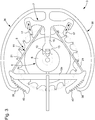
Fig. 1 est une vue schématique en coupe d'un mécanisme de tourbillon pour un mécanisme horloger, selon une forme d'exécution de l'invention ; - La
Fig. 2 est une vue d'une partie d'échappement d'un mécanisme de tourbillon pour un mécanisme horloger, selon une forme d'exécution de l'invention ; - La
Fig. 3 est une vue d'une partie d'échappement d'un mécanisme de tourbillon pour un mécanisme horloger, selon une autre forme d'exécution de l'invention.
- The
Fig. 1 is a schematic sectional view of a tourbillon mechanism for a watchmaking mechanism, according to one embodiment of the invention; - The
Fig. 2 is a view of an exhaust part of a tourbillon mechanism for a watch mechanism according to one embodiment of the invention; - The
Fig. 3 is a view of an exhaust part of a tourbillon mechanism for a watch mechanism, according to another embodiment of the invention.
Faisant référence aux figures, un mécanisme de tourbillon pour un mouvement horloger comprend un mécanisme de balancier 2 et un mécanisme d'échappement 3 montés dans une cage 12.Referring to the figures, a tourbillon mechanism for a watch movement comprises a
Le mécanisme de balancier 2 comprend un ressort 14 et une roue de balancier 16 fixée sur un axe 18 monté de manière pivotante dans la cage 12. Les extrémités 20 opposées de l'axe sont logées dans des paliers 26 disposés dans des parois opposées 28a, 28b de la cage 12. Un ressort 14, qui est dans la forme d'exécution illustrée, sous forme d'une spirale, est fixé par une première extrémité à l'axe 18 (ou directement à la roue de balancier), et par son autre extrémité à la cage 12 de manière à appliquer une force élastique de rotation relative entre la roue de balancier 16 et la cage 12.The
Le mécanisme d'échappement comprend une roue d'échappement 5 munie de dents 9, une ancre 7, et un dispositif de plateau 4 couplé au balancier 2.The escape mechanism comprises an
L'ancre comprend une fourchette 13, des palettes 17, 17a, 17b, et une baguette 15 reliant les palettes à la fourchette. La baguette est couplée en rotation à la cage 12 au moyen d'un dispositif pivot 11 élastique que nous décrirons plus en détail ci-dessous. La baguette 15 et les palettes 17 pivotent autour d'un axe de rotation Za virtuel se trouvant, dans l'exemple représenté, entre les palettes 17a, 17b approximativement au croisement des fibres neutres des lames élastiques.The anchor includes a
Les palettes coopèrent avec les dents 9 de la roue d'échappement. Une palette constitue la palette d'entrée 17a et l'autre constitue la palette de sortie 17b. L'ancre comprend en outre un dard 27 fixé sur la fourchette au moyen par exemple d'un axe chassé ou collé dans un trou de fixation à la base de la fourchette. Le dispositif de plateau 4 comprend un grand plateau 6 avec une cheville 10 qui engage les cornes de la fourchette 13 et un petit plateau 8 muni d'une encoche 16 pour le passage du dard 27. Le mécanisme illustré fonctionne selon le principe d'un échappement de type à ancre suisse. Ce principe étant en soi bien connu, les éléments classiques et leur fonctionnement ne seront pas décrits en détail dans la présente.The vanes cooperate with the
Les dents 9 de la roue d'échappement pointent vers l'extérieur de la roue et les palettes 17a, 17b sont disposées radialement à l'extérieur de la roue d'échappement et pointent vers l'intérieur, à savoir vers l'axe de rotation de la cage du tourbillon. Cela permet avantageusement d'augmenter la longueur des bras élastiques 21 du dispositif pivot 11 tout en assurant un mécanisme d'échappement compact. La cage 12 est montée de manière rotative, au moyen de paliers 30a, 30b, dans un bâti 22 ou structure fixe du mouvement horloger. La cage 12 est reliée à une source d'énergie fournissant un couple de rotation sur la cage. Cette source d'énergie peut être couplée à la cage au moyen d'un rouage d'entrainement 24 engrenant un pignon 32 fixé ou solidaire du corps de la cage 12. Un axe de seconde 34 peut être fixé ou être solidaire de la cage 12, par exemple en s'étendant du centre du pignon 32 à travers le palier 30b, aligné avec l'axe de rotation Z0 de la cage 12. Une aiguille d'affichage des secondes (non-illustrée) peut être fixée à l'extrémité libre de l'axe de seconde 34. D'autres configurations sont toutefois possibles, par exemple l'affichage de secondes peut être couplé par un dispositif de rouages (non-illustré) au pignon 32 ou à une autre roue solidaire ou fixé à la cage 12.The
Les composants formant le mécanisme de balancier 2 ainsi que l'ancre 7 du mécanisme d'échappement 3 sont portés par la cage 12 et tournent donc avec la cage par rapport au bâti 22 ou à une structure fixe du mouvement horloger. La roue d'échappement 5 est fixée ou solidaire du bâti ou d'une structure fixe du mouvement horloger.The components forming the
Pendant que la roue de balancier parcourt son arc d'oscillation et que l'une des palettes 17a, 17b engage une dent 9 de la roue d'échappement 5, la cage 12 reste immobile, ainsi que le mécanisme d'échappement 3 et le rouage d'entrainement 24. La cage est bien sous l'effet de la force motrice qui agit sur le pignon de cage 32, mais aucune rotation n'est possible car l'ancre 7, qui est fixé au corps de la cage 12, est arrêtée contre une dent de la roue d'échappement 5 qui est en relation fixe avec le bâti.While the rocker wheel traverses its oscillation arc and one of the
Dès que la palette 17a, 17b est libérée d'une dent de la roue d'échappement, la cage 12 tourne d'un petit angle, par exemple d'un angle égal au déplacement de l'aiguille de seconde, pour s'immobiliser aussitôt que les fonctions d'échappement sont terminées et que l'une des palettes 17a, 17b est de nouveau arrêtée contre une dent 9 de la roue d'échappement 5. Après ce déplacement, l'ensemble porté par la cage 12 occupe une nouvelle position de repos.As soon as the
Pendant la rotation de la cage 12, le pignon 32 est entraîné dans un mouvement de rotation, provoqué par son engrènement dans la denture du rouage d'entrainement 24.During rotation of the
Le mécanisme de balancier 2 se trouve à l'intérieur et dans l'axe de rotation de la cage 12 et ses pivots tournent dans des paliers solidaires de la cage. Quant aux autres pièces de l'échappement à l'exception de la roue d'échappement 5, elles pivotent avec la cage 12. Ainsi, dans un temps relativement court, par exemple en une minute, par sauts successifs, toute la cage 12 aura accompli un tour en entraînant avec elle tous les organes qu'elle porte. On sait que la marche d'une montre diffère selon la position verticale dans laquelle elle est observée, la cause essentielle provenant du déséquilibre ou balourd du balancier et de celui du spiral. En faisant prendre au dispositif balancier toutes les positions en rotation, par exemple d'un tour par minute, on obtient un brassage des positions verticales qui se solde par une marche moyenne compensant ces différences.The
Dans des formes d'exécution, telles que illustrées dans les
La zone d'ancrage peut être fixée directement au corps 28 de la cage 12, ou à un organe fixé de manière statique à la cage 12. Dans une variante, la zone d'ancrage 12a peut aussi être formée d'un seul tenant avec le corps 28 de la cage 12. L'ancre 7 peut avantageusement être formée d'un seul tenant avec le ou les bras élastiques 21.The anchoring zone can be fixed directly to the
Dans une forme d'exécution avantageuse, le dispositif pivot comprend au moins deux bras élastiques 21 connectés de part et d'autre de la baguette 15 de l'ancre. Dans la variante illustrée, les au moins deux bras élastiques 21 avec la zone d'ancrage 12a forment essentiellement un triangle. Les bras élastiques peuvent avantageusement être disposés essentiellement dans un plan orthogonal à l'axe de rotation Za virtuel de l'ancre. Les bras élastiques peuvent notamment être réalisés sous la forme de lames minces. D'autres formes et configurations de bras élastiques sont toutefois possibles dans le cadre de l'invention dans la mesure où ils remplissent la double fonction de support et de ressort, pour supporter l'ancre et simultanément permettre à l'ancre de pivoter pour la fonction d'échappement. Dans la forme d'exécution illustrée, le dispositif pivot 11 sert donc en tant que ressort et de support pour l'ancre 7 pivotant autour de l'axe de rotation Za , sans avoir besoin d'un autre pivot ou support pour l'ancre. Cela permet avantageusement, entre autres, de réduire les pertes dues aux frottements dans des paliers, et de réduire l'encombrement de l'ensemble comprenant l'ancre et son support. Par ailleurs il n'y pas de besoin de lubrification du pivot.In an advantageous embodiment, the pivot device comprises at least two
Dans le cadre de l'invention, il est aussi possible d'avoir une ancre comprenant un axe de pivot supporté par des paliers solidaires de la cage ou fixés à la cage. L'axe de pivot serait disposé à une position alignée avec l'axe de rotation Za virtuel de l'ancre illustré dans les
Dans le cas de la variante selon la
Dans cette variante avec un mécanisme de pivot bistable, le tirage via les angles sur les palettes peut être réduit ou supprimé car cette fonction est remplie par la bistabilité du mécanisme de pivot. Cela permet d'augmenter le rendement du système d'échappement.In this variant with a bistable pivot mechanism, the draft via the corners on the pallets can be reduced or eliminated because this function is fulfilled by the bistability of the pivot mechanism. This increases the efficiency of the exhaust system.
Avantageusement, selon une forme d'exécution le dispositif pivot 11 ou un ensemble d'éléments solidaires avec le dispositif pivot tels qu'une partie 15, 13 de l'ancre 7 ou l'entier de l'ancre, et/ou encore une partie de la cage 12 ou l'entier de la cage, et/ou encore le ressort 14 du mécanisme de balancier peuvent être formés par des procédés de dépôt ou de gravage.Advantageously, according to one embodiment the
Dans des formes d'exécution, le dispositif pivot ou l'ensemble d'éléments solidaires peuvent notamment être formés en métal précieux ou non, typiquement par la technique électroformage connue sous l'abréviation L.I.G.A. provenant des termes allemands « RôntgenLithographie, Galvanoformung & Abformung » et dans laquelle on remplit un moule à un ou plusieurs niveaux à l'aide d'un métal, par exemple, à l'aide d'une galvanoplastie de Ni ou de Ni-P. Bien entendu, tout type d'électroformage, du type L.I.G.A. ou non, capable de former l'ensemble ou une partie du dispositif pivot décrit plus haut est envisageable.In embodiments, the pivot device or the set of integral elements may in particular be formed of precious metal or not, typically by the electroforming technique known by the abbreviation L.I.G.A. from the German terms "RoentgenLithography, Galvanoformung & Abformung" and in which a single or multi-level mold is filled with a metal, for example, by electroplating Ni or Ni-P . Of course, any type of electroforming, type L.I.G.A. or not, capable of forming all or part of the pivot device described above is possible.
Dans des formes d'exécution, le dispositif pivot ou l'ensemble d'éléments solidaires peuvent avantageusement former une structure monolithique.In embodiments, the pivot device or the set of integral elements may advantageously form a monolithic structure.
Dans des formes d'exécution, le dispositif pivot ou l'ensemble d'éléments solidaires peuvent être en une matière à base de silicium.In embodiments, the pivot device or the set of integral members may be of a silicon-based material.
Dans des formes d'exécution, le dispositif pivot ou l'ensemble d'éléments solidaires peuvent être fabriqués par un procédé de silicium sur isolant appelé « SOI » (de l'anglais : Silicon On Insulator). Dans cette variante, la structure est constituée d'un empilement d'une couche de silicium sur une couche d'isolant. Cet isolant peut par exemple être du dioxyde de silicium (SiO2). La plaquette de SOI subit un plusieurs gravages successifs à travers des masques de formes appropriée. Les gravages peuvent être réalisés par voie humide ou par voie sèche. Typiquement on utilisera un gravage ionique réactif profond anisotrope également connu sous l'abréviation D.R.I.E. provenant des termes anglais « Deep Reactive Ion Etching ».In embodiments, the pivot device or the set of integral elements may be manufactured by a silicon on insulator process called "SOI" (Silicon On Insulator). In this variant, the structure consists of a stack of a silicon layer on an insulating layer. This insulator may for example be silicon dioxide (SiO2). The SOI plate undergoes several successive engravings through masks of appropriate shapes. Engravings can be made wet or dry. Typically one will use a deep anisotropic reactive ion etching also known by the abbreviation D.R.I.E. from the words "Deep Reactive Ion Etching".
Dans des formes d'exécution le dispositif pivot ou l'ensemble d'éléments solidaires peuvent être en métal amorphe.In embodiments, the pivot device or the set of integral elements may be of amorphous metal.
Le dispositif pivot ou l'ensemble d'éléments solidaires peuvent aussi comporter des structures sacrificielles qui aident à l'assemblage.The pivot device or the set of integral elements may also include sacrificial structures that assist in assembly.
L'invention permet avantageusement d'améliorer le fonctionnement d'un mécanisme de tourbillon par rapport aux solutions conventionnelles en supprimant un mobile dans la cage du mécanisme de tourbillon Le mécanisme de tourbillon résultant peut être ainsi beaucoup plus plat car il y a un mobile en moins et le rendement est amélioré car l'inertie est plus faible. En effet, le mécanisme de tourbillon selon des formes d'exécution de l'invention peut avoir une plus faible inertie de par son plus faible nombre de composants. Dans une variante utilisant la bistabilité du guidage flexible, cela permet de réduire le tirage sur les palettes et réduire ou supprimer le recul, ce qui permet d'améliorer le rendement.The invention advantageously makes it possible to improve the operation of a vortex mechanism with respect to conventional solutions by eliminating a mobile in the cage of the vortex mechanism. The resulting vortex mechanism can thus be much flatter because there is a mobile in less and the yield is improved because the inertia is lower. Indeed, the vortex mechanism according to embodiments of the invention may have a lower inertia due to its smaller number of components. In a variant using the bistability of the flexible guide, this reduces the draft on the pallets and reduce or eliminate the recoil, which improves the efficiency.
-
mouvement horloger
22 bâti
30 paliers- 24 rouage d'entrainement
- 1 mécanisme de tourbillon
- 2 mécanisme de balancier
- 14 ressort
- 16 roue de balancier
- 18 axe
- 20 extrémités
- 3 mécanisme d'échappement
- 5 une roue d'échappement
9 dent - 7 une ancre
- 11 dispositif pivot
- 21 bras élastique
- 12a élément de support
- 26 mécanisme bistable
- 36 tirant élastique
38 crochet - 40 dents de rochet
- 36 tirant élastique
- 12a zone d'ancrage
- 13 fourchette
27 dard - 15 baguette
- 17 palettes
- palette d'entrée 17a
- palette de sortie 17b
- 11 dispositif pivot
- 5 une roue d'échappement
- 4 dispositif plateau
- 6 grand plateau
10 cheville - 8 petit plateau
encoche
- 6 grand plateau
- 12 cage
- 28 corps
- 28a, 28b parois
26 paliers - 32 pignon d'échappement
34 roue de seconde
- 28a, 28b parois
22 built
30 steps- 24 training wheels
- 1 swirl mechanism
- 2 pendulum mechanism
- 14 spring
- 16 balance wheel
- 18 axis
- 20 ends
- 3 exhaust mechanism
- 5 an escape wheel
9 tooth - 7 an anchor
- 11 pivot device
- 21 elastic arm
- 12a support element
- 26 bistable mechanism
- 36 elastic pulling
38 hook - 40 ratchet teeth
- 36 elastic pulling
- 12a anchoring area
- 13 fork
27 dard - 15 sticks
- 17 pallets
-
entry pallet 17a -
output pallet 17b
-
- 11 pivot device
- 5 an escape wheel
- 4 tray device
- 6 large tray
10 ankle - 8 small platter
nick
- 6 large tray
- 12 cage
- 28 bodies
- 28a, 28b walls
26 steps - 32 exhaust pinion
34 second wheel
- 28a, 28b walls
- 24 rouage d'entrainement
- Z0 axe de rotation du dispositif de tourbillon Z 0 axis of rotation of the vortex device
- Za axe de rotation virtuel de l'ancre Z a virtual axis of rotation of the anchor
Claims (13)
- Tourbillon mechanism for a timepiece movement, comprising a balance mechanism (2), an escapement mechanism (3) and a carriage (12) mounted in a structure of the timepiece movement in rotation about a tourbillon axis (Z0), the balance mechanism comprising a spring (14) and a balance wheel (16) mounted in the carriage to pivot about said tourbillon axis, the escapement mechanism comprising an escape wheel (5) with teeth (9) and a pallet-lever (7) comprising pallet-stones (17, 17a, 17b) configured to engage said teeth, the pallet-lever being mounted in the carriage and coupled in rotation to the carriage by means of a pivot device (11), wherein the escape wheel encircles the tourbillon axis and is attached to or integral with said structure of the timepiece movement, which mechanism is characterized in that the pivot device is configured to pivot elastically and to support the pallet-lever, and in that the pivot device includes one or more elastic arms (21) connecting the pallet-lever to an anchoring area (12a) attached to, or integral with the carriage.
- Mechanism according to the preceding claim, characterized in that the pivot device includes a pair of said elastic arms.
- Mechanism according to the preceding claim, characterized in that the pair of elastic arms form an essentially triangular shape with the anchoring area.
- Mechanism according to any of the preceding claims, characterized in that the pallet-lever pivots about a virtual axis of rotation (Za) located at the intersection of the neutral fibres of the elastic arms.
- Mechanism according to any of the preceding claims, characterized in that the escape wheel teeth point outwards from the wheel and the pallet-stones are disposed radially on the outside of the escape wheel and point towards the inside of the wheel.
- Mechanism according to any of the preceding claims, characterized in that the carriage is connected to an energy source providing a rotational torque on the carriage, the energy source being coupled to the carriage by means of a drive train (24) meshing with a pinion (32) that is attached to or integral with the carriage.
- Method of manufacturing a mechanism according to any of the preceding claims, characterized in that the pivot device or a set of elements integral with the pivot device are formed by deposition or etching methods.
- Method of manufacturing a mechanism according to the preceding claim, characterized in that the set of elements integral with the pivot device includes one or more of the following elements: part of the pallet-lever or the entire pallet-lever; part of the carriage or the entire carriage; the spring of the balance mechanism.
- Method of manufacturing a mechanism according to any of the preceding two claims, characterized in that the pivot device or the set of elements integral with the pivot device form a one-piece structure.
- Method of manufacturing a mechanism according to one of the preceding three claims, characterized in that the deposition method comprises a LIGA electroforming method.
- Method of manufacturing a mechanism according to any of the preceding two claims, characterized in that the pivot device or the set of elements integral with the pivot device are made of one or more of the following materials: silicon-based material, Ni, NiP, amorphous metal.
- Mechanism according to any of claims 1 to 6, characterized in that the pivot device includes a bistable mechanism (26).
- Watch movement including a mechanism according to any of claims 1 to 6 or claim 12.
Priority Applications (7)
| Application Number | Priority Date | Filing Date | Title |
|---|---|---|---|
| EP14196157.3A EP3029530B1 (en) | 2014-12-03 | 2014-12-03 | Tourbillon mechanism |
| TW104137893A TWI675268B (en) | 2014-12-03 | 2015-11-17 | Tourbillon mechanism |
| JP2015230605A JP6195888B2 (en) | 2014-12-03 | 2015-11-26 | Tool-bilon mechanism |
| US14/955,597 US9599961B2 (en) | 2014-12-03 | 2015-12-01 | Tourbillon mechanism |
| KR1020150170870A KR101799648B1 (en) | 2014-12-03 | 2015-12-02 | Tourbillon mechanism |
| CN201510881968.4A CN105676616B (en) | 2014-12-03 | 2015-12-03 | Top flywheel mechanism |
| HK16113884A HK1225813B (en) | 2014-12-03 | 2016-12-06 | Tourbillon mechanism |
Applications Claiming Priority (1)
| Application Number | Priority Date | Filing Date | Title |
|---|---|---|---|
| EP14196157.3A EP3029530B1 (en) | 2014-12-03 | 2014-12-03 | Tourbillon mechanism |
Publications (2)
| Publication Number | Publication Date |
|---|---|
| EP3029530A1 EP3029530A1 (en) | 2016-06-08 |
| EP3029530B1 true EP3029530B1 (en) | 2019-08-14 |
Family
ID=52000765
Family Applications (1)
| Application Number | Title | Priority Date | Filing Date |
|---|---|---|---|
| EP14196157.3A Active EP3029530B1 (en) | 2014-12-03 | 2014-12-03 | Tourbillon mechanism |
Country Status (7)
| Country | Link |
|---|---|
| US (1) | US9599961B2 (en) |
| EP (1) | EP3029530B1 (en) |
| JP (1) | JP6195888B2 (en) |
| KR (1) | KR101799648B1 (en) |
| CN (1) | CN105676616B (en) |
| HK (1) | HK1225813B (en) |
| TW (1) | TWI675268B (en) |
Families Citing this family (11)
| Publication number | Priority date | Publication date | Assignee | Title |
|---|---|---|---|---|
| EP3136187B1 (en) * | 2015-08-31 | 2018-02-28 | Glashütter Uhrenbetrieb GmbH | Mechanical clock comprising a tourbillon |
| CH713144A1 (en) * | 2016-11-17 | 2018-05-31 | Richemont Int Sa | Exhaust for timepiece. |
| EP3451075B1 (en) * | 2017-08-21 | 2020-06-24 | Montres Breguet S.A. | Clock movement comprising a multiaxial tourbillon |
| FR3073056A1 (en) * | 2017-10-28 | 2019-05-03 | Daniel Galazzo | COMPACT OSCILLATOR-EXHAUST SYSTEMS FOR WATCHES |
| JP7103041B2 (en) * | 2018-08-03 | 2022-07-20 | セイコーエプソン株式会社 | Ankles, movements, watches |
| EP3770696B1 (en) * | 2019-07-23 | 2021-12-01 | Omega SA | Timepiece stop-cage with lifting finger and stopping finger |
| EP3770695B1 (en) * | 2019-07-23 | 2022-01-12 | Omega SA | Timepiece stop-cage with blade for stopping the cage |
| EP3812843A1 (en) * | 2019-10-25 | 2021-04-28 | ETA SA Manufacture Horlogère Suisse | Flexible guide and set of stacked flexible guides for rotary resonator mechanism, in particular for a clock movement |
| JP6748318B1 (en) * | 2020-01-29 | 2020-08-26 | セイコーウオッチ株式会社 | Escapement governor, watch movement and watch |
| EP3982206A1 (en) * | 2020-10-07 | 2022-04-13 | Patek Philippe SA Genève | Timepiece oscillator |
| CH718187A1 (en) * | 2020-12-17 | 2022-06-30 | Mft Dhorlogerie Audemars Piguet Sa | Tourbillon for watch movement. |
Family Cites Families (9)
| Publication number | Priority date | Publication date | Assignee | Title |
|---|---|---|---|---|
| GB2375619B (en) * | 2001-05-14 | 2002-12-24 | Souza Paul Gerard D | Differential tourbillon escapement for clocks & watches |
| CH701725B1 (en) * | 2006-09-25 | 2011-03-15 | Franck Mueller Watchland S A | Tourbillon timepiece. |
| CH702707B1 (en) | 2007-04-05 | 2011-08-31 | Complitime Sa | workpiece movement of tourbillon watches. |
| CN201402376Y (en) * | 2009-04-10 | 2010-02-10 | 天津海鸥表业集团有限公司 | Stop mechanism of flying tourbillon |
| CH701490A1 (en) * | 2009-07-17 | 2011-01-31 | Franck Mueller Watchland S A | A whirlwind of fixed wheel exhaust. |
| EP2818941A1 (en) * | 2010-04-01 | 2014-12-31 | Rolex Sa | Device for locking a sprocket wheel |
| CN104204966B (en) * | 2012-03-29 | 2017-02-22 | 尼瓦洛克斯-法尔股份有限公司 | Flexible escapement mechanism having a mobile frame |
| EP2725433B1 (en) * | 2012-10-26 | 2015-04-29 | Richemont International S.A. | Flying pendulum with flying balance wheel for clockwork |
| CH707808B1 (en) * | 2013-03-19 | 2017-05-15 | Nivarox Far Sa | Watch mechanism cassette. |
-
2014
- 2014-12-03 EP EP14196157.3A patent/EP3029530B1/en active Active
-
2015
- 2015-11-17 TW TW104137893A patent/TWI675268B/en active
- 2015-11-26 JP JP2015230605A patent/JP6195888B2/en active Active
- 2015-12-01 US US14/955,597 patent/US9599961B2/en active Active
- 2015-12-02 KR KR1020150170870A patent/KR101799648B1/en active IP Right Grant
- 2015-12-03 CN CN201510881968.4A patent/CN105676616B/en active Active
-
2016
- 2016-12-06 HK HK16113884A patent/HK1225813B/en unknown
Non-Patent Citations (1)
| Title |
|---|
| None * |
Also Published As
| Publication number | Publication date |
|---|---|
| KR20160067053A (en) | 2016-06-13 |
| TWI675268B (en) | 2019-10-21 |
| US20160161915A1 (en) | 2016-06-09 |
| CN105676616A (en) | 2016-06-15 |
| TW201635061A (en) | 2016-10-01 |
| HK1225813B (en) | 2017-09-15 |
| US9599961B2 (en) | 2017-03-21 |
| JP6195888B2 (en) | 2017-09-13 |
| KR101799648B1 (en) | 2017-12-20 |
| EP3029530A1 (en) | 2016-06-08 |
| JP2016109683A (en) | 2016-06-20 |
| CN105676616B (en) | 2018-01-23 |
Similar Documents
| Publication | Publication Date | Title |
|---|---|---|
| EP3029530B1 (en) | Tourbillon mechanism | |
| EP3545365B1 (en) | Flexibly guided rotary resonator maintained by a free escapement with pallets | |
| EP2246752B1 (en) | Tourbillon without the balance weight. | |
| EP3182213B2 (en) | Mechanism for adjusting an average speed in a clock movement and clock movement | |
| EP2706416A1 (en) | Constant force flexible anchor | |
| CH709328B1 (en) | Escapement, timepiece movement and timepiece. | |
| EP3040783B1 (en) | Sub-assembly for a mechanism for adjusting a speed in a clock movement and such a mechanism | |
| EP2466397B1 (en) | Rotating clock component with peripheral guide | |
| EP1640821B1 (en) | Watch movement with a plurality of balances | |
| CH710487A2 (en) | tourbillon mechanism. | |
| CH714361A2 (en) | Flexible guided rotary resonator serviced by a free anchor escapement. | |
| CH713530A2 (en) | Exhaust, timepiece movement and timepiece. | |
| EP3663868B1 (en) | Clock movement including a tourbillon with a fixed magnetic wheel | |
| EP3561603A1 (en) | Timepiece regulator mechanism with hinged resonators | |
| EP4016195B1 (en) | Tourbillon for a clockwork | |
| EP3479175B1 (en) | Mechanical clock movement | |
| CH704239A2 (en) | Single block watch making mobile e.g. escape mechanism, for use during movement of mechanical watch, has guide surface located close to plane so as to maintain mobile in recessed or overhang manner, where mobile does not have guide shaft |
Legal Events
| Date | Code | Title | Description |
|---|---|---|---|
| PUAI | Public reference made under article 153(3) epc to a published international application that has entered the european phase |
Free format text: ORIGINAL CODE: 0009012 |
|
| AK | Designated contracting states |
Kind code of ref document: A1 Designated state(s): AL AT BE BG CH CY CZ DE DK EE ES FI FR GB GR HR HU IE IS IT LI LT LU LV MC MK MT NL NO PL PT RO RS SE SI SK SM TR |
|
| AX | Request for extension of the european patent |
Extension state: BA ME |
|
| STAA | Information on the status of an ep patent application or granted ep patent |
Free format text: STATUS: REQUEST FOR EXAMINATION WAS MADE |
|
| 17P | Request for examination filed |
Effective date: 20161208 |
|
| RBV | Designated contracting states (corrected) |
Designated state(s): AL AT BE BG CH CY CZ DE DK EE ES FI FR GB GR HR HU IE IS IT LI LT LU LV MC MK MT NL NO PL PT RO RS SE SI SK SM TR |
|
| REG | Reference to a national code |
Ref country code: DE Ref legal event code: R079 Ref document number: 602014051676 Country of ref document: DE Free format text: PREVIOUS MAIN CLASS: G04B0017280000 Ipc: G04B0031000000 |
|
| RIC1 | Information provided on ipc code assigned before grant |
Ipc: G04B 17/28 20060101ALI20190320BHEP Ipc: G04B 31/00 20060101AFI20190320BHEP |
|
| GRAP | Despatch of communication of intention to grant a patent |
Free format text: ORIGINAL CODE: EPIDOSNIGR1 |
|
| STAA | Information on the status of an ep patent application or granted ep patent |
Free format text: STATUS: GRANT OF PATENT IS INTENDED |
|
| INTG | Intention to grant announced |
Effective date: 20190430 |
|
| GRAS | Grant fee paid |
Free format text: ORIGINAL CODE: EPIDOSNIGR3 |
|
| GRAA | (expected) grant |
Free format text: ORIGINAL CODE: 0009210 |
|
| STAA | Information on the status of an ep patent application or granted ep patent |
Free format text: STATUS: THE PATENT HAS BEEN GRANTED |
|
| AK | Designated contracting states |
Kind code of ref document: B1 Designated state(s): AL AT BE BG CH CY CZ DE DK EE ES FI FR GB GR HR HU IE IS IT LI LT LU LV MC MK MT NL NO PL PT RO RS SE SI SK SM TR |
|
| REG | Reference to a national code |
Ref country code: GB Ref legal event code: FG4D Free format text: NOT ENGLISH |
|
| REG | Reference to a national code |
Ref country code: CH Ref legal event code: EP Ref country code: AT Ref legal event code: REF Ref document number: 1167745 Country of ref document: AT Kind code of ref document: T Effective date: 20190815 |
|
| REG | Reference to a national code |
Ref country code: IE Ref legal event code: FG4D Free format text: LANGUAGE OF EP DOCUMENT: FRENCH |
|
| REG | Reference to a national code |
Ref country code: DE Ref legal event code: R096 Ref document number: 602014051676 Country of ref document: DE |
|
| REG | Reference to a national code |
Ref country code: CH Ref legal event code: NV Representative=s name: ICB INGENIEURS CONSEILS EN BREVETS SA, CH |
|
| REG | Reference to a national code |
Ref country code: NL Ref legal event code: MP Effective date: 20190814 |
|
| REG | Reference to a national code |
Ref country code: LT Ref legal event code: MG4D |
|
| PG25 | Lapsed in a contracting state [announced via postgrant information from national office to epo] |
Ref country code: HR Free format text: LAPSE BECAUSE OF FAILURE TO SUBMIT A TRANSLATION OF THE DESCRIPTION OR TO PAY THE FEE WITHIN THE PRESCRIBED TIME-LIMIT Effective date: 20190814 Ref country code: BG Free format text: LAPSE BECAUSE OF FAILURE TO SUBMIT A TRANSLATION OF THE DESCRIPTION OR TO PAY THE FEE WITHIN THE PRESCRIBED TIME-LIMIT Effective date: 20191114 Ref country code: NL Free format text: LAPSE BECAUSE OF FAILURE TO SUBMIT A TRANSLATION OF THE DESCRIPTION OR TO PAY THE FEE WITHIN THE PRESCRIBED TIME-LIMIT Effective date: 20190814 Ref country code: SE Free format text: LAPSE BECAUSE OF FAILURE TO SUBMIT A TRANSLATION OF THE DESCRIPTION OR TO PAY THE FEE WITHIN THE PRESCRIBED TIME-LIMIT Effective date: 20190814 Ref country code: FI Free format text: LAPSE BECAUSE OF FAILURE TO SUBMIT A TRANSLATION OF THE DESCRIPTION OR TO PAY THE FEE WITHIN THE PRESCRIBED TIME-LIMIT Effective date: 20190814 Ref country code: NO Free format text: LAPSE BECAUSE OF FAILURE TO SUBMIT A TRANSLATION OF THE DESCRIPTION OR TO PAY THE FEE WITHIN THE PRESCRIBED TIME-LIMIT Effective date: 20191114 Ref country code: PT Free format text: LAPSE BECAUSE OF FAILURE TO SUBMIT A TRANSLATION OF THE DESCRIPTION OR TO PAY THE FEE WITHIN THE PRESCRIBED TIME-LIMIT Effective date: 20191216 Ref country code: LT Free format text: LAPSE BECAUSE OF FAILURE TO SUBMIT A TRANSLATION OF THE DESCRIPTION OR TO PAY THE FEE WITHIN THE PRESCRIBED TIME-LIMIT Effective date: 20190814 |
|
| REG | Reference to a national code |
Ref country code: AT Ref legal event code: MK05 Ref document number: 1167745 Country of ref document: AT Kind code of ref document: T Effective date: 20190814 |
|
| PG25 | Lapsed in a contracting state [announced via postgrant information from national office to epo] |
Ref country code: RS Free format text: LAPSE BECAUSE OF FAILURE TO SUBMIT A TRANSLATION OF THE DESCRIPTION OR TO PAY THE FEE WITHIN THE PRESCRIBED TIME-LIMIT Effective date: 20190814 Ref country code: GR Free format text: LAPSE BECAUSE OF FAILURE TO SUBMIT A TRANSLATION OF THE DESCRIPTION OR TO PAY THE FEE WITHIN THE PRESCRIBED TIME-LIMIT Effective date: 20191115 Ref country code: IS Free format text: LAPSE BECAUSE OF FAILURE TO SUBMIT A TRANSLATION OF THE DESCRIPTION OR TO PAY THE FEE WITHIN THE PRESCRIBED TIME-LIMIT Effective date: 20191214 Ref country code: AL Free format text: LAPSE BECAUSE OF FAILURE TO SUBMIT A TRANSLATION OF THE DESCRIPTION OR TO PAY THE FEE WITHIN THE PRESCRIBED TIME-LIMIT Effective date: 20190814 Ref country code: LV Free format text: LAPSE BECAUSE OF FAILURE TO SUBMIT A TRANSLATION OF THE DESCRIPTION OR TO PAY THE FEE WITHIN THE PRESCRIBED TIME-LIMIT Effective date: 20190814 Ref country code: ES Free format text: LAPSE BECAUSE OF FAILURE TO SUBMIT A TRANSLATION OF THE DESCRIPTION OR TO PAY THE FEE WITHIN THE PRESCRIBED TIME-LIMIT Effective date: 20190814 |
|
| PG25 | Lapsed in a contracting state [announced via postgrant information from national office to epo] |
Ref country code: TR Free format text: LAPSE BECAUSE OF FAILURE TO SUBMIT A TRANSLATION OF THE DESCRIPTION OR TO PAY THE FEE WITHIN THE PRESCRIBED TIME-LIMIT Effective date: 20190814 |
|
| PG25 | Lapsed in a contracting state [announced via postgrant information from national office to epo] |
Ref country code: DK Free format text: LAPSE BECAUSE OF FAILURE TO SUBMIT A TRANSLATION OF THE DESCRIPTION OR TO PAY THE FEE WITHIN THE PRESCRIBED TIME-LIMIT Effective date: 20190814 Ref country code: PL Free format text: LAPSE BECAUSE OF FAILURE TO SUBMIT A TRANSLATION OF THE DESCRIPTION OR TO PAY THE FEE WITHIN THE PRESCRIBED TIME-LIMIT Effective date: 20190814 Ref country code: IT Free format text: LAPSE BECAUSE OF FAILURE TO SUBMIT A TRANSLATION OF THE DESCRIPTION OR TO PAY THE FEE WITHIN THE PRESCRIBED TIME-LIMIT Effective date: 20190814 Ref country code: RO Free format text: LAPSE BECAUSE OF FAILURE TO SUBMIT A TRANSLATION OF THE DESCRIPTION OR TO PAY THE FEE WITHIN THE PRESCRIBED TIME-LIMIT Effective date: 20190814 Ref country code: EE Free format text: LAPSE BECAUSE OF FAILURE TO SUBMIT A TRANSLATION OF THE DESCRIPTION OR TO PAY THE FEE WITHIN THE PRESCRIBED TIME-LIMIT Effective date: 20190814 Ref country code: AT Free format text: LAPSE BECAUSE OF FAILURE TO SUBMIT A TRANSLATION OF THE DESCRIPTION OR TO PAY THE FEE WITHIN THE PRESCRIBED TIME-LIMIT Effective date: 20190814 |
|
| PG25 | Lapsed in a contracting state [announced via postgrant information from national office to epo] |
Ref country code: IS Free format text: LAPSE BECAUSE OF FAILURE TO SUBMIT A TRANSLATION OF THE DESCRIPTION OR TO PAY THE FEE WITHIN THE PRESCRIBED TIME-LIMIT Effective date: 20200224 Ref country code: SM Free format text: LAPSE BECAUSE OF FAILURE TO SUBMIT A TRANSLATION OF THE DESCRIPTION OR TO PAY THE FEE WITHIN THE PRESCRIBED TIME-LIMIT Effective date: 20190814 Ref country code: CZ Free format text: LAPSE BECAUSE OF FAILURE TO SUBMIT A TRANSLATION OF THE DESCRIPTION OR TO PAY THE FEE WITHIN THE PRESCRIBED TIME-LIMIT Effective date: 20190814 Ref country code: SK Free format text: LAPSE BECAUSE OF FAILURE TO SUBMIT A TRANSLATION OF THE DESCRIPTION OR TO PAY THE FEE WITHIN THE PRESCRIBED TIME-LIMIT Effective date: 20190814 |
|
| REG | Reference to a national code |
Ref country code: DE Ref legal event code: R097 Ref document number: 602014051676 Country of ref document: DE |
|
| PLBE | No opposition filed within time limit |
Free format text: ORIGINAL CODE: 0009261 |
|
| STAA | Information on the status of an ep patent application or granted ep patent |
Free format text: STATUS: NO OPPOSITION FILED WITHIN TIME LIMIT |
|
| PG2D | Information on lapse in contracting state deleted |
Ref country code: IS |
|
| 26N | No opposition filed |
Effective date: 20200603 |
|
| REG | Reference to a national code |
Ref country code: BE Ref legal event code: MM Effective date: 20191231 |
|
| PG25 | Lapsed in a contracting state [announced via postgrant information from national office to epo] |
Ref country code: MC Free format text: LAPSE BECAUSE OF FAILURE TO SUBMIT A TRANSLATION OF THE DESCRIPTION OR TO PAY THE FEE WITHIN THE PRESCRIBED TIME-LIMIT Effective date: 20190814 Ref country code: SI Free format text: LAPSE BECAUSE OF FAILURE TO SUBMIT A TRANSLATION OF THE DESCRIPTION OR TO PAY THE FEE WITHIN THE PRESCRIBED TIME-LIMIT Effective date: 20190814 |
|
| PG25 | Lapsed in a contracting state [announced via postgrant information from national office to epo] |
Ref country code: LU Free format text: LAPSE BECAUSE OF NON-PAYMENT OF DUE FEES Effective date: 20191203 Ref country code: IE Free format text: LAPSE BECAUSE OF NON-PAYMENT OF DUE FEES Effective date: 20191203 |
|
| PG25 | Lapsed in a contracting state [announced via postgrant information from national office to epo] |
Ref country code: BE Free format text: LAPSE BECAUSE OF NON-PAYMENT OF DUE FEES Effective date: 20191231 |
|
| PG25 | Lapsed in a contracting state [announced via postgrant information from national office to epo] |
Ref country code: CY Free format text: LAPSE BECAUSE OF FAILURE TO SUBMIT A TRANSLATION OF THE DESCRIPTION OR TO PAY THE FEE WITHIN THE PRESCRIBED TIME-LIMIT Effective date: 20190814 |
|
| PG25 | Lapsed in a contracting state [announced via postgrant information from national office to epo] |
Ref country code: MT Free format text: LAPSE BECAUSE OF FAILURE TO SUBMIT A TRANSLATION OF THE DESCRIPTION OR TO PAY THE FEE WITHIN THE PRESCRIBED TIME-LIMIT Effective date: 20190814 Ref country code: HU Free format text: LAPSE BECAUSE OF FAILURE TO SUBMIT A TRANSLATION OF THE DESCRIPTION OR TO PAY THE FEE WITHIN THE PRESCRIBED TIME-LIMIT; INVALID AB INITIO Effective date: 20141203 |
|
| PG25 | Lapsed in a contracting state [announced via postgrant information from national office to epo] |
Ref country code: MK Free format text: LAPSE BECAUSE OF FAILURE TO SUBMIT A TRANSLATION OF THE DESCRIPTION OR TO PAY THE FEE WITHIN THE PRESCRIBED TIME-LIMIT Effective date: 20190814 |
|
| PGFP | Annual fee paid to national office [announced via postgrant information from national office to epo] |
Ref country code: CH Payment date: 20230101 Year of fee payment: 9 |
|
| P01 | Opt-out of the competence of the unified patent court (upc) registered |
Effective date: 20230611 |
|
| PGFP | Annual fee paid to national office [announced via postgrant information from national office to epo] |
Ref country code: GB Payment date: 20231121 Year of fee payment: 10 |
|
| PGFP | Annual fee paid to national office [announced via postgrant information from national office to epo] |
Ref country code: FR Payment date: 20231122 Year of fee payment: 10 Ref country code: DE Payment date: 20231121 Year of fee payment: 10 |