EP3136187B1 - Mechanical clock comprising a tourbillon - Google Patents
Mechanical clock comprising a tourbillon Download PDFInfo
- Publication number
- EP3136187B1 EP3136187B1 EP15183133.6A EP15183133A EP3136187B1 EP 3136187 B1 EP3136187 B1 EP 3136187B1 EP 15183133 A EP15183133 A EP 15183133A EP 3136187 B1 EP3136187 B1 EP 3136187B1
- Authority
- EP
- European Patent Office
- Prior art keywords
- balance
- zero
- cage
- clockwork movement
- movement according
- Prior art date
- Legal status (The legal status is an assumption and is not a legal conclusion. Google has not performed a legal analysis and makes no representation as to the accuracy of the status listed.)
- Active
Links
- 230000033001 locomotion Effects 0.000 claims description 97
- 238000006073 displacement reaction Methods 0.000 claims description 9
- 230000008878 coupling Effects 0.000 claims description 4
- 238000010168 coupling process Methods 0.000 claims description 4
- 238000005859 coupling reaction Methods 0.000 claims description 4
- 238000004146 energy storage Methods 0.000 description 8
- 230000009471 action Effects 0.000 description 6
- 230000005764 inhibitory process Effects 0.000 description 3
- 230000003993 interaction Effects 0.000 description 3
- 230000007246 mechanism Effects 0.000 description 3
- 230000007480 spreading Effects 0.000 description 3
- 238000000034 method Methods 0.000 description 2
- 230000008569 process Effects 0.000 description 2
- 230000001360 synchronised effect Effects 0.000 description 2
- 102000015933 Rim-like Human genes 0.000 description 1
- 108050004199 Rim-like Proteins 0.000 description 1
- 230000003213 activating effect Effects 0.000 description 1
- 230000004913 activation Effects 0.000 description 1
- 230000005540 biological transmission Effects 0.000 description 1
- 244000309464 bull Species 0.000 description 1
- 238000010276 construction Methods 0.000 description 1
- 230000003247 decreasing effect Effects 0.000 description 1
- 230000001419 dependent effect Effects 0.000 description 1
- 230000009977 dual effect Effects 0.000 description 1
- 230000000694 effects Effects 0.000 description 1
- 239000003112 inhibitor Substances 0.000 description 1
- 230000002045 lasting effect Effects 0.000 description 1
- 239000007788 liquid Substances 0.000 description 1
- 230000007935 neutral effect Effects 0.000 description 1
- 230000002093 peripheral effect Effects 0.000 description 1
Images


Classifications
-
- G—PHYSICS
- G04—HOROLOGY
- G04B—MECHANICALLY-DRIVEN CLOCKS OR WATCHES; MECHANICAL PARTS OF CLOCKS OR WATCHES IN GENERAL; TIME PIECES USING THE POSITION OF THE SUN, MOON OR STARS
- G04B17/00—Mechanisms for stabilising frequency
- G04B17/20—Compensation of mechanisms for stabilising frequency
- G04B17/28—Compensation of mechanisms for stabilising frequency for the effect of unbalance of the weights, e.g. tourbillon
- G04B17/285—Tourbillons or carrousels
-
- G—PHYSICS
- G04—HOROLOGY
- G04B—MECHANICALLY-DRIVEN CLOCKS OR WATCHES; MECHANICAL PARTS OF CLOCKS OR WATCHES IN GENERAL; TIME PIECES USING THE POSITION OF THE SUN, MOON OR STARS
- G04B17/00—Mechanisms for stabilising frequency
- G04B17/04—Oscillators acting by spring tension
- G04B17/06—Oscillators with hairsprings, e.g. balance
- G04B17/063—Balance construction
-
- G—PHYSICS
- G04—HOROLOGY
- G04B—MECHANICALLY-DRIVEN CLOCKS OR WATCHES; MECHANICAL PARTS OF CLOCKS OR WATCHES IN GENERAL; TIME PIECES USING THE POSITION OF THE SUN, MOON OR STARS
- G04B27/00—Mechanical devices for setting the time indicating means
- G04B27/004—Mechanical devices for setting the time indicating means having several simultaneous functions, e.g. stopping or starting the clockwork or the hands
-
- G—PHYSICS
- G04—HOROLOGY
- G04B—MECHANICALLY-DRIVEN CLOCKS OR WATCHES; MECHANICAL PARTS OF CLOCKS OR WATCHES IN GENERAL; TIME PIECES USING THE POSITION OF THE SUN, MOON OR STARS
- G04B27/00—Mechanical devices for setting the time indicating means
- G04B27/005—Mechanical devices for setting the time indicating means stepwise or on determined values
-
- G—PHYSICS
- G04—HOROLOGY
- G04B—MECHANICALLY-DRIVEN CLOCKS OR WATCHES; MECHANICAL PARTS OF CLOCKS OR WATCHES IN GENERAL; TIME PIECES USING THE POSITION OF THE SUN, MOON OR STARS
- G04B27/00—Mechanical devices for setting the time indicating means
- G04B27/02—Mechanical devices for setting the time indicating means by making use of the winding means
- G04B27/026—Mechanical devices for setting the time indicating means by making use of the winding means for several clockworks or pairs of hands and/or supplementary functions
Definitions
- the present invention relates to a mechanical movement with a tourbillon and a mechanical clock equipped therewith.
- Tourbillons for mechanical watches and movements are well known.
- the escape wheel, the anchor and the so-called balance of the movement are arranged on a bogie, which is coupled to the shaft of the second wheel, and thus the second drive, or firmly connected.
- the balance or balance axis typically coincides with an imaginary axle extension of the second drive.
- a gearwheel connected to the escape wheel meshes with a stationary gear wheel arranged coaxially with the balance axis, so that the tourbillon, and therefore its frame, undergoes a complete revolution per minute.
- balance rest which can be activated for example by pulling out a crown and deactivated by pushing the crown wheel back.
- a rest stop for a tourbillon is from the EP 2 793 087 A1 known. This has a with the balance engageable and axially to the balance axis movable brake element. To balance the clock with a time standard, it is thus possible to stop the balance and thus the tourbillon mechanism as desired.
- the present invention is an object of the invention to provide an improved rest stop for a tourbillon of a mechanical watch.
- a zero position of the tourbillon for comfortable timing can be realized. This is to improve the operability and the time setting of the clock and also give the clock an increased range of functions.
- a clockwork of a mechanical watch with a tourbillon unit is provided.
- the movement has a board on which all movable components of the movement are arranged.
- the movement, in particular its tourbillon unit further has a frame connected to a second drive, rotatably mounted on the board frame and mounted on the frame balance.
- a second drive In addition to the balance, an escape wheel in operative connection with the balance is also mounted on the frame.
- the escape wheel is typically via an armature in operative connection with the balance.
- the balance, the anchor and the escape wheel form the inhibition of the mechanical movement.
- the second drive is typically coupled to an energy storage device, such as a barrel, which ultimately drives the movement.
- the movement is further provided with a balance engageable with the balance rest device.
- the balance stop device By means of the balance stop device, the balance for stopping the movement relative to the board or relative to the frame at least temporarily fixed.
- the movement is provided with a zeroing device, which allows to adjust the angular orientation of the frame in a predetermined position, which preferably corresponds to the zero position of a mounted on the frame second hand.
- the zeroing device is optionally rotatably engageable with the frame or with the board.
- the zeroing device is typically in the normal operation of the clock with the circuit board rotatably engaged.
- the zeroing device is fixed relative to or on the board, while the frame together with the entire tourbillon unit is subjected to a rotational movement relative to the board.
- the zeroing device is also detachable from the circuit board or rotatably decoupled, so that it can be rotated relative to the board. In this case, it is typically rotatably engaged with the frame.
- the zeroing device is thus always either with the frame rotatably engaged or rotatably engaged with the board or the zeroing device is even with both the frame and the circuit board rotatably engaged.
- rotatably engageable zeroing device By selectively with the frame or with the board rotatably engageable zeroing device can be achieved to decouple the frame for adjusting the time at least temporarily from the energy storage device of the movement.
- an alternate fixation or rotationally fixed connection of the zeroing device with the frame or with the board can be achieved that the zeroing device together with the frame to bring about a zero stop function also approximately under the action of the mechanical Energy storage of the movement, but decoupled from the minute or hourly drive of the movement in a defined zero position can be converted.
- the optional engagement of the zeroing device with the frame or with the board can be done by successive and stepwise pulling out a crown, such as an elevator or Einstellkrone the clockwork.
- a crown such as an elevator or Einstellkrone the clockwork.
- the crown may be in three different axial positions, ie a first so-called rest position in which, for example, a barrel can be wound through the crown as usual, a second position in which the balance is stopped, eg according to the solution of EP2793087 , and a third further drawn axial position in which the zeroing device is no longer engaged with the board, but now with the frame in engagement.
- the minute hand position can be provided by turning the crown in this position.
- the zeroing device in a basic configuration, is fixed against rotation on the circuit board.
- the crown In the basic configuration, the crown is in a basic position, in which the movement is driven by the mechanical energy storage in motion. Due to the fixation on the board, the zeroing device acts as a kind of basis for the tourbillon unit. It may be provided in particular that the tourbillon unit or part thereof with the Zero setting are in operative connection. In the basic configuration with a zero-setting device fixed on the board, this only acts as a carrier for other mechanical components of the movement, for example for the tourbillon unit or for individual components thereof.
- the zeroing device is non-rotatably coupled to the frame when the balance is stopped by means of the balance rest stop device.
- the frame is freely rotatably mounted relative to the board. That is, only under the influence of the inhibition, the frame rotates relative to the board under the action of the spring drive outgoing mechanical drive energy.
- the zeroing device and the balance stop device interact with one another in such a way that the zeroing device is rotationally fixedly coupled to the frame by activating the balance stop device. It is also conceivable that the zeroing device is already firmly connected to the balance stop device. A fixation of the frame relative to the board by means of the balance rest device thus inevitably leads to a rotationally fixed fixing of the frame relative to the zeroing device.
- the zeroing device By a direct or indirect coupling of zeroing device and frame can be achieved that about the purpose of setting the clock, the zeroing device is rotatably connected to the frame. By means of the zeroing device can then be transferred from any position in which the frame was stopped, the frame fixed thereto in a defined zero position in which a second hand arranged on the frame pointer points to zero.
- the balance stop device has a bogie and frictionally engaged with the balance in Engage engageable axially to a balance axis movable brake element.
- a balance rest can be realized, which exerts no radial asymmetric forces on the balance or on the bogie of the tourbillon.
- the balance can also be braked directly via the brake element, in particular stopped. By slowing down and stopping the balance will inevitably stop the rotation of the tourbillon, that is, the rotational movement of the bogie.
- the balance-rest device acts exclusively on the balance in the axial direction makes the balance-rest stop device particularly suitable for achieving a rest stop in the case of a flying tourbillon.
- a frictional braking of the balance also allows the balance to be stopped in any arbitrary orientation and position of the balance.
- the zeroing device via the brake element rotatably coupled to the frame.
- the zeroing device can, in particular, act directly or indirectly on the brake element arranged, for example, on the frame.
- the zeroing device but at least individual components or parts thereof may or may be in particular in the power flow of the balance rest stop device.
- the zeroing device by means of a fixing member rotationally fixed to the board can be fixed.
- the zeroing device can optionally be fixed in a rotationally fixed manner to the printed circuit board or else detached therefrom, so that the zeroing device is rotatable with respect to the printed circuit board.
- the fixing element can be transferred only in a rotationally fixed coupling of frame and zeroing device in a release position, in which the zeroing device is rotatable together with the frame relative to the board.
- the frame is coupled to the zeroing device and the fixing element is transferred to the release position, typically an optionally damped rotational movement of the ensemble formed by frame and zeroing ensembles, wherein the bogie is operatively connected by the activated balance device with the energy storage device of the movement.
- the second drive of the tourbillon is in this configuration still with the energy storage device of the movement, such as the barrel, in mechanical operative connection.
- a pawl is further arranged to be movable on the board. This cooperates with a frame arranged on the locking cam to stop the frame in a neutral position.
- the pawl for example, can be transferred radially inwardly into a locking position, in which they are so with the locking cam of the Gestells cooperates, which prevents rotation of the frame beyond the pawl or past the pawl.
- the latching cam may, for example, protrude radially outward from the frame.
- the pawl is, for example, in a radially inwardly engaged detent position and the zeroing device together with the frame subject of a rotary motion at a located in the release position fixing element, the locking cam of the frame comes into engagement with the pawl.
- the pawl thus acts as an end stop for the locking cam and thus for the frame so that it comes to rest in the intended zero position for adjusting the movement.
- the pawl is coupled to the fixing element.
- the pawl is at least only in a detent position for stopping the frame when the fixing passes from the fixing position in the release position.
- the pawl and the fixing are so far rigidly coupled together. If the ensemble of frame and zeroing device is released for rotational movement, the pawl engages radially inward to stop the free rotation of the ensemble at a fixed predetermined position.
- detent cam and pawl thus determines the zero position of the frame and thus the arranged on the frame second hand of the tourbillon.
- the zeroing device has a carrier wheel with a rim-like circulation tire.
- the circulating tire is rotatably mounted on its outer circumference at least three arranged on the board bearing rollers.
- the zeroing device has in particular a ring-like basic geometry.
- the hub of the tourbillon unit typically extends through the remaining center of the nulling device.
- the zeroing device on a ring-like epicyclic gear with an internal toothing, which meshes with a pinion of the escape wheel.
- the planetary gear of the zeroing device which is also fixed relative to the board in the basic configuration or while the movement is running, meshes with the escape wheel.
- the escapement wheel moves in particular due to the teeth of its pinion with the internal toothing along that internal toothing, when the tourbillon unit is subject to a prevailing during operation of the movement rotational movement.
- the zeroing device acts in this respect as an extended board, on the internal toothing of which the escape wheel runs along with its pinion.
- the zeroing device has a, relative to its axis of rotation, axially movable stop ring. This has on a radially outer edge on a run-on slope, which corresponds to a run-on slope of a movable arranged on the board stop pawl. Typically, two diametrically opposed stop pawls are provided. These can experience a radially inwardly directed movement in the direction of the stop ring with a pulling out of the crown.
- stop ring undergoes an axial movement when the stop pawl or the pawls are moved radially inward.
- a radial movement can thus be converted into an axial movement.
- the at least one pawl of the zeroing device can be deflected radially inwards by an axial movement of the stop ring induced by means of the at least one stop pawl.
- the at least one pawl at its radially inner end on a run-on slope, which is engageable with a run-on slope of a brake ring.
- the brake ring is typically disposed axially adjacent the pawl and is also axially slidable relative to the zeroing device on a major axis of the tourbillon unit, for example, on the hub of the tourbillon unit. Since the at least one pawl and the brake ring engaging therewith have mutually corresponding run-on slopes, the typically radially inwardly directed pivoting or adjusting movement of the pawl can be transmitted into an axially directed displacement movement of the brake ring.
- a brake pin is axially movably guided in a hub of the tourbillon unit or in the frame and for the deflection of the brake element and for stopping the balance by means of the brake ring axially is displaceable.
- the brake pin is in particular against a restoring force, in particular against the action of a spring element axially displaceable to the brake ring.
- the brake pin deflects the brake element, which is movable axially relative to the balance spring, in such a way that it frictionally engages with the balance and finally stops the balance.
- At the zeroing device is typically not only one, but there are several, approximately three circumferentially equidistantly arranged pawls provided, which perform a synchronous, radially inwardly directed movement due to an axial movement of the adjacent thereto arranged stop ring. Accordingly, a possible uniform and symmetrical displacement force can be exerted on the brake ring, which ultimately leads to the axial propulsion of the brake pin.
- a watch in particular a mechanical wristwatch is provided, which is equipped with a previously described movement.
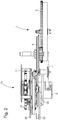
- a tourbillon unit 10 of a mechanical movement 1 not shown in its entirety is illustrated.
- the movement 1 has a board 2, on which the tourbillon unit 10 is rotatably mounted.
- the tourbillon unit 10 is, as from a synopsis of Fig. 2 and 11 emerges coupled via a second drive 5 with a Kleinêtrad 7.
- the Kleinêtrad 7 meshes with a minute wheel 8, which is in engagement with a barrel 9, which in the present case acts as a mechanical energy storage device.
- the tourbillon unit 10 also has an in Fig. 11 shown in cross-section hub 6, which is rotatably mounted on the board 2 and fixedly connected to a frame 11 of the tourbillon unit 10.
- the frame 11 comprises a lower frame 11a with various radially aligned spokes 11d, via which the frame 11 is connected to the hub 6. About the outer circumference of the lower frame 11 a three vertically or axially aligned pillar 11 c are arranged in the present case. At the lower frame 11a facing away from the end portion, an upper frame 11b is arranged. Between the upper and the lower frame 11a, 11a, the balance 15 of the movement 1 is mounted. The balance 15 is pivotally mounted with respect to a balance shaft 17, wherein the balance shaft 17 is in extension of the second drive 5.
- the balance 15 is further coupled to a balance spring 16.
- an escapement 14 is also provided on the frame 11 so far an escape wheel 12 is rotatably mounted.
- the axis of rotation of the escape wheel 12 in this case extends parallel to the balance axis 17.
- the escapement 14 also has an anchor, which is not explicitly shown here, which alternately engages with the teeth of the escape wheel 14 in a known manner.
- the balance 16, the anchor not explicitly shown and the escape wheel 12 form the escapement 14.
- the escape wheel 12 is provided with a pinion 19 which meshes with an internal toothing 49 of a zeroing device 40.
- the zeroing device 40 is fixed to the board 2 during normal operation of the movement 1.
- the stepwise rotational movement of the escape wheel 12 thus leads to a rotation of the entire frame 11 with respect to the board 2.
- a second hand 18 is further arranged, which protrudes with a pointer tip radially outwardly from the frame 11, in this case from the upper frame 11b ,
- the rotational position of the frame 11 thus reflects the seconds of a time display.
- a balance stop device 50 In addition to the zeroing device 40, the movement 1 on a balance stop device 50, by means of which the balance 15 can be stopped or stopped if necessary.
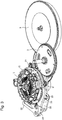
- the multi-part construction of the zeroing device 40 is based on Fig. 4 to 10 clarified.
- the zeroing device 40 has a carrier wheel 41, which centrally has a passage opening 71.
- the carrier wheel 41 has an annular contour.
- the central passage opening 71 is delimited in particular by an inner edge 72, as shown in FIG Fig. 4 is indicated. From the inner edge 72 project over the circumference of the inner edge 72 distributed distributed pawls 45 radially inwardly. These are rotatably or pivotally mounted in the plane of the carrier wheel 41. They are like a comparison of Fig. 4 and 7 clarified, radially inwardly deflectable.
- Each of the pawls 45 has at its free and inwardly projecting end on a Steueranlaufschräge 45 a. At the bottom of the pawls 45, a dome-shaped latch cam 47 is formed in each case. Further, each of the pawls 45 is coupled to a pawl spring 46, by means of which the individual pawls 45 are deflected radially inwardly against a spring force. The radially inwardly directed deflection takes place via an axial force acting on the pawl cams 47. With decreasing force effect, the individual pawl springs 46 cause a movement of the pawls 45 radially outwards, in the in Fig. 4 shown starting position.
- a circulating tire 44 is formed at the radially outer edge of the carrier wheel 41 of the zeroing device 40 at the radially outer edge of the carrier wheel 41 of the zeroing device 40 at the radially outer edge of the carrier wheel 41 of the zeroing device 40 at the radially outer edge of the carrier wheel 41 of the zeroing device 40 at the radially outer edge of the carrier wheel 41 of the zeroing device 40 at the radially outer edge of the carrier wheel 41 of the zeroing device 40 is, as in Fig. 5 shown, on the one hand a circulating tire 44 is formed at the radially offset thereto, the carrier wheel 41 has an external toothing 48. At the top of the carrier wheel 41, a peripheral wheel 42 is arranged. The planet wheel 42 also has an annular contour. On an inner side of the planetary gear 42 is a circumferential internal teeth 49 formed, which, as already mentioned, with the pinion 19 of the balance 15 meshes.
- a stop ring 43 is further attached on the underside of the carrier wheel 41.
- the stop ring 43 has an outer run-on slope 53 on its outer edge.
- the stop ring 43 is mounted axially displaceably on the carrier wheel 41.
- the stop ring 43 further has, as in Fig. 5 shown via a further run-on slope 54 at its inner edge.
- the inner starting bevel 54 of the stop ring 43 can engage with the pawl cams 47.
- An upward axial movement of the stop ring 43 towards the carrier wheel 41 thus causes a radially inwardly directed deflection of the three pawls 45. This is based on a comparison of Fig. 5 and 8th or the Fig. 6 and 9 recognizable.
- the entire zeroing device 40 is rotatably mounted on the circuit board 2 via the circulating tire 44 at a plurality of bearing rollers 31 distributed over the circumference of the zeroing device 40.
- the zeroing device 40 via a fixing element 30, which is configured here as a fixing lever, on the circuit board 2 releasably fixed.
- a free end of the fixing element 30 is frictionally engaged with an outer edge of the zeroing device 40, for example.
- the zeroing device 40 can be released so that it is rotatable relative to the board 2 with respect to a central axis of rotation 73.
- the axis of rotation 73 of the zeroing device 40 may coincide in particular with the balance axis 70 and with the axis of the secondary drive 5.
- a brake element 60 On a top side of the lower frame 11a, a brake element 60, in the present case in the form of a flat brake spring, is also arranged.
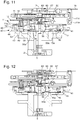
- the brake element 60 in particular its free and radially inwardly projecting end, is arranged axially movably on the frame 11. It is in particular by means of an axially displaceable in the hub 6 or on the frame 11 brake pin 58 from a starting position, as in Fig. 11 shown in a braking position, as in Fig. 12 shown, deflectable.
- the brake pin 58 is located with a head in a recess of the lower frame 11 a. By an axially upward deflection of the brake pin 58 presses axially on the brake member 60, so that its free end rubbing and in the axial direction with a corresponding thereto configured friction surface of a double roller 62 engages, which is connected to the balance 15. In this way, the balance 15 can be stopped and fixed with respect to the frame 11.
- the brake pin 58 is by means of an axially displaceably mounted brake ring 56 of the in Fig. 11 shown initial or basic position in the in Fig. 12 shown braking position can be transferred.
- the brake ring 56 Radially outward and at the lower end, the brake ring 56 on a run-on slope 56a, which is formed circumferentially and corresponding to the control starting slope 45a of the pawls 45 configured.
- a radially inwardly directed pivoting movement of the pawls 45 thus leads to an upward, in the direction of the frame 11 directed axial displacement of the brake ring 56, whereby the brake pin 58 and hereby also the brake member 60 axially displaced or axially deflected.
- the brake element 60 By the radially inwardly directed pivoting movement of the pawls 45, the brake element 60 finally comes with the double roller 62 of the balance 15 into engagement.
- the axial displacement of the brake ring 56 relative to the hub 6 or relative to the frame 11 takes place counter to the restoring force of a spreading spring 57, which is arranged axially between the hub 6 and the brake ring 56.
- a spreading spring 57 which is arranged axially between the hub 6 and the brake ring 56.
- the pawls 45 under the action of their respective pawl springs 46 back into the in Fig. 4 swung back starting position shown takes place under the action of the spreading spring 57 also equally a movement of the brake ring 56 in his in Fig. 11 shown starting position.
- the balance 15 is released again, causing the stopped movement 1 automatically starts again.
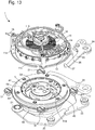
- first and second stop pawls 20, 22 are provided on the outer circumference of the zeroing device 40, as these in Fig. 13 are shown.
- the first stop pawl 20 and second stop pawl 22 are pivotally mounted on the board 2.
- a first run-on slope 21, and a second run-on slope 23 are provided. These are formed for example in the form of conical wheels.
- the respective first and second run-on slopes 21, 23 of the respective first and second stop pawls 20, 22 are located at the level of the outer run-on slope 53 provided on the outer edge of the stop ring 43.
- a radially inwardly directed pivoting of the first and second stop pawls 20, 22 leads to a uniform lifting or axial displacement of the stop ring 43 from the in Fig. 11 shown starting position or basic configuration in the in Fig. 12 illustrated stop configuration.
- the position of the first and second chamfers 21, 23 in the FIGS. 11 and 12 not explicitly shown.
- the axial movement of the stop ring 43 leads, as already described, to the radially inwardly directed deflection of the pawls 45 and thus to an axial displacement of the brake pin 58 and ultimately to the balance 15 lasting deflection of the brake element 60th
- That one stopping of the movement 1 causing synchronous pivotal movement of the two first and second pawls 20, 22 can be done by pulling a crown in a predetermined detent position. The movement 1 is thus stopped. Is the present not explicitly shown crown, starting from that stop configuration in a further, for example, pulled out in a second detent position, this causes a coupled pivoting of the fixing element 30 and a pawl 26th
- the frame 11 is freely rotatably mounted on the board 2. Due to the mutual engagement of pawl 26 and locking cam 28, a defined end stop for the frame 11, thus created for the entire tourbillon unit 10, so that the second hand 18 typically comes to rest on the twelve.
- the fixing element 30 engaging with the zeroing device 40 is deflected radially outward. As a result, the zeroing device 40 is transferred into a release position, so that their rotational fixation is canceled relative to the board 2.
- the coupled movement of pawl 26 and fixing member 30 is via an in Fig. 13 indicated control lever 24 initiated.
- the pivoting movements of the fixing element 30 and the pawl 26 are rigidly coupled together. It is in any case necessary to ensure that the fixing lever 30 can only be transferred to its release position when the pawl 26 is in its locked position.
- the second hand 18 In this axial position of the crown, the second hand 18 thus automatically moves into a well-defined zero position or zero position, without the crown having to be further manipulated.
- the usual interaction of a zeroing lever with a common zero heart is no longer needed.
- the zero position of the secondary pointer 18 is effected by a combined rotational movement of the zeroing device 40 and the tourbillon unit 10 driven by the barrel via the second drive 5, this rotary movement can preferably be damped or braked by means of a separate braking mechanism.
- the braking mechanism not explicitly shown here, for example, can be permanently engaged with the external toothing 48 of the zeroing device 40, for example. That braking device can act, for example, as a rotary damper.
- the rotary damper is realized as a hydraulic damper module which is in engagement with the external toothing 48 of the zeroing device 40 via an intermediate gear.
- both the gear ratios in this transmission chain, as well as the viscosity of the liquid of the hydraulic damper module can be adjusted for an adapted rotational speed.
- the conical first and second chamfers 21, 23 are used in addition to the bearing rollers 31 of the radial and axial bearing of the zeroing device 40 on the board. 2
- the fixing element 30 first comes into frictional engagement with the zeroing device 40 again. Then the pawl 26 is transferred from its rest position back to a starting position. As a result, on the one hand, the zeroing device 40 is again fixed to the board 2, while the frame 11 is disengaged from the pawl 26.
Description
Die vorliegende Erfindung betrifft ein mechanisches Uhrwerk mit einem Tourbillon sowie eine hiermit ausgestattete mechanische Uhr.The present invention relates to a mechanical movement with a tourbillon and a mechanical clock equipped therewith.
Tourbillons für mechanische Uhren und Uhrwerke sind hinlänglich bekannt. Hierbei sind das Ankerrad, der Anker und die sogenannte Unruh des Uhrwerks auf einem Drehgestell angeordnet, welches mit der Welle des Sekundenrads, mithin dem Sekundentrieb, gekoppelt bzw. fest verbunden ist. Die Unruh bzw. die Unruhachse fällt hierbei typischerweise mit einer gedachte Achsverlängerung des Sekundentriebs zusammen. Ein mit dem Ankerrad verbundenes Zahnrad kämmt schließlich mit einem koaxial zur Unruhachse angeordneten feststehenden Zahnrad, sodass das Tourbillon, mithin dessen Gestell, pro Minute eine vollständige Umdrehung erfährt.Tourbillons for mechanical watches and movements are well known. Here, the escape wheel, the anchor and the so-called balance of the movement are arranged on a bogie, which is coupled to the shaft of the second wheel, and thus the second drive, or firmly connected. The balance or balance axis typically coincides with an imaginary axle extension of the second drive. Finally, a gearwheel connected to the escape wheel meshes with a stationary gear wheel arranged coaxially with the balance axis, so that the tourbillon, and therefore its frame, undergoes a complete revolution per minute.
Für das genaue Einstellen einer mechanischen Zeigeruhr ist es erforderlich, die Sekundenanzeige anzuhalten. Bei herkömmlichen Uhrwerken wird dies zumeist durch einen sogenannten Unruhstopp realisiert, welcher zum Beispiel durch Herausziehen einer Krone aktiviert und durch Hineindrücken des Kronrads wieder deaktiviert werden kann.For the exact setting of a mechanical watch, it is necessary to stop the seconds display. In conventional movements this is usually realized by a so-called balance rest, which can be activated for example by pulling out a crown and deactivated by pushing the crown wheel back.
Bei Uhren mit Minutentourbillon, bei welchen die Sekundenanzeige direkt durch das Drehgestell des Tourbillons realisiert ist, gestaltet sich die Verwirklichung eines derartigen Unruhstopps als überaus schwierig und kompliziert.In watches with minute tourbillon, in which the seconds display is realized directly through the bogie of the tourbillon, the realization of such trouble-rest designed as extremely difficult and complicated.
Ein Unruhstopp für ein Tourbillon ist beispielsweise aus der
Demgegenüber liegt der vorliegenden Erfindung nun die Aufgabe zugrunde, einen verbesserten Unruhstopp für ein Tourbillon einer mechanischen Uhr bereitzustellen. Zusätzlich zum Anhalten des Tourbillons soll ferner eine Nullstellung des Tourbillons zur komfortablen Zeiteinstellung verwirklicht werden. Dies soll die Bedienbarkeit und die Zeiteinstellung der Uhr verbessern und der Uhr ferner einen gesteigerten Funktionsumfang verleihen.In contrast, the present invention is an object of the invention to provide an improved rest stop for a tourbillon of a mechanical watch. In addition to stopping the tourbillon is also a zero position of the tourbillon for comfortable timing can be realized. This is to improve the operability and the time setting of the clock and also give the clock an increased range of functions.
Diese Aufgabe wird mit einem Uhrwerk mit einer Tourbilloneinheit nach dem unabhängigen Patentanspruch 1 sowie mit einer ein derartiges Uhrwerk aufweisenden Uhr nach Patentanspruch 15 gelöst. Vorteilhafte Ausgestaltungen sind dabei Gegenstand abhängiger Patentansprüche.This object is achieved with a movement with a tourbillon unit according to the
Insoweit ist ein Uhrwerk einer mechanischen Uhr mit einer Tourbilloneinheit vorgesehen. Das Uhrwerk weist eine Platine auf, an welcher sämtliche bewegliche Komponenten des Uhrwerks angeordnet sind. Das Uhrwerk, insbesondere seine Tourbilloneinheit weist ferner ein mit einem Sekundentrieb verbundenes, drehbar an der Platine gelagertes Gestell sowie eine am Gestell gelagerte Unruh auf. Neben der Unruh ist an dem Gestell ferner ein mit der Unruh in Wirkverbindung stehendes Ankerrad gelagert. Das Ankerrad steht typischerweise über einen Anker in Wirkverbindung mit der Unruh. Unruh, Anker und Ankerrad bilden hierbei die Hemmung des mechanischen Uhrwerks. Der Sekundentrieb ist typischerweise mit einer Energiespeichereinrichtung, etwa mit einem Federhaus, gekoppelt, welches das Uhrwerk letztlich antreibt.In that regard, a clockwork of a mechanical watch with a tourbillon unit is provided. The movement has a board on which all movable components of the movement are arranged. The movement, in particular its tourbillon unit further has a frame connected to a second drive, rotatably mounted on the board frame and mounted on the frame balance. In addition to the balance, an escape wheel in operative connection with the balance is also mounted on the frame. The escape wheel is typically via an armature in operative connection with the balance. The balance, the anchor and the escape wheel form the inhibition of the mechanical movement. The second drive is typically coupled to an energy storage device, such as a barrel, which ultimately drives the movement.
Das Uhrwerk ist ferner mit einer mit der Unruh in Eingriff bringbaren Unruhstoppvorrichtung versehen. Mittels der Unruhstoppvorrichtung ist die Unruh zum Anhalten des Uhrwerks relativ zur Platine bzw. relativ zum Gestell zumindest temporär fixierbar. Des Weiteren ist das Uhrwerk mit einer Nullstelleinrichtung versehen, die es erlaubt, die Winkelausrichtung des Gestells in einer vorbestimmten Position einzustellen, die vorzugsweise der Nullage eines auf dem Gestells angebrachten Sekundenzeigers entspricht. Gemäss einer bevorzugten Ausführungsform ist die Nullstelleinrichtung wahlweise mit dem Gestell oder mit der Platine drehfest in Eingriff bringbar ist. Die Nullstelleinrichtung ist typischerweise im Normalbetrieb der Uhr mit der Platine drehfest in Eingriff.The movement is further provided with a balance engageable with the balance rest device. By means of the balance stop device, the balance for stopping the movement relative to the board or relative to the frame at least temporarily fixed. Furthermore, the movement is provided with a zeroing device, which allows to adjust the angular orientation of the frame in a predetermined position, which preferably corresponds to the zero position of a mounted on the frame second hand. According to a preferred embodiment, the zeroing device is optionally rotatably engageable with the frame or with the board. The zeroing device is typically in the normal operation of the clock with the circuit board rotatably engaged.
Das heißt, die Nullstelleinrichtung ist relativ zur oder an der Platine fixiert, während das Gestell zusammen mit der gesamten Tourbilloneinheit einer Drehbewegung relativ zur Platine ausgesetzt ist. Bei angehaltenem Uhrwerk, insbesondere zum Einstellen der Uhrzeit, ist die Nullstelleinrichtung aber auch von der Platine lösbar oder drehbeglich entkoppelbar, sodass sie relativ zur Platine gedreht werden kann. Dabei ist sie typischerweise mit dem Gestell drehfest in Eingriff. Die Nullstelleinrichtung ist somit stets entweder mit dem Gestell drehfest in Eingriff oder mit der Platine drehfest in Eingriff oder aber die Nullstelleinrichtung ist sogar mit beiden, dem Gestell und der Platine drehfest in Eingriff.That is, the zeroing device is fixed relative to or on the board, while the frame together with the entire tourbillon unit is subjected to a rotational movement relative to the board. When the movement is stopped, in particular for setting the time, the zeroing device is also detachable from the circuit board or rotatably decoupled, so that it can be rotated relative to the board. In this case, it is typically rotatably engaged with the frame. The zeroing device is thus always either with the frame rotatably engaged or rotatably engaged with the board or the zeroing device is even with both the frame and the circuit board rotatably engaged.
Durch die wahlweise mit dem Gestell oder mit der Platine drehfest in Eingriff bringbare Nullstelleinrichtung kann erreicht werden, das Gestell zum Einstellen der Uhrzeit zumindest temporär von der Energiespeichereinrichtung des Uhrwerks zu entkoppeln. Durch eine alternierende Fixierung bzw. drehfeste Verbindung der Nullstelleinrichtung mit dem Gestell oder mit der Platine kann erreicht werden, dass die Nullstelleinrichtung zusammen mit dem Gestell zur Herbeiführung einer Nullstoppfunktion auch etwa unter Einwirkung des mechanischen Energiespeichers des Uhrwerks, aber entkoppelt vom Minuten- oder Stundentrieb des Uhrwerks in eine definierte Nullstellung überführbar ist.By selectively with the frame or with the board rotatably engageable zeroing device can be achieved to decouple the frame for adjusting the time at least temporarily from the energy storage device of the movement. By an alternate fixation or rotationally fixed connection of the zeroing device with the frame or with the board can be achieved that the zeroing device together with the frame to bring about a zero stop function also approximately under the action of the mechanical Energy storage of the movement, but decoupled from the minute or hourly drive of the movement in a defined zero position can be converted.
Das wahlweise In-Eingriff-Bringen der Nullstelleinrichtung mit dem Gestell oder mit der Platine kann durch sukzessives und schrittweises herausziehen einer Krone, beispielsweise einer Aufzugs- oder Einstellkrone des Uhrwerks erfolgen. Gemäss einer bevorzugten Ausführungsform des beanspruchten Uhrwerks kann sich die Krone in drei verschiedenen axialen Positionen befinden, d.h. einer ersten sogenannten Ruheposition, in welcher z.B. ein Federhaus wie üblich durch die Krone aufgezogen werden kann, einer zweiten Position in welcher die Unruh gestoppt wird, z.B. wie gemäss der Lösung von
Nach einer Weiterbildung ist vorgesehen, dass in einer Grundkonfiguration die Nullstelleinrichtung drehfest an der Platine fixiert ist. In der Grundkonfiguration befindet sich die Krone in einer Grundstellung, in welcher das Uhrwerk angetrieben vom mechanischen Energiespeicher in Gang ist. Durch die Fixierung an der Platine fungiert die Nullstelleinrichtung als eine Art Basis für die Tourbilloneinheit. Es kann insbesondere vorgesehen sein, dass die Tourbilloneinheit oder Teil hiervon mit der Nullstelleinrichtung in Wirkverbindung stehen. In der Grundkonfiguration bei einer an der Platine fixierten Nullstelleinrichtung fungiert diese lediglich als Träger für weitere mechanische Komponenten des Uhrwerks, etwa für die Tourbilloneinheit oder für einzelne Komponenten hiervon.According to a development, it is provided that in a basic configuration, the zeroing device is fixed against rotation on the circuit board. In the basic configuration, the crown is in a basic position, in which the movement is driven by the mechanical energy storage in motion. Due to the fixation on the board, the zeroing device acts as a kind of basis for the tourbillon unit. It may be provided in particular that the tourbillon unit or part thereof with the Zero setting are in operative connection. In the basic configuration with a zero-setting device fixed on the board, this only acts as a carrier for other mechanical components of the movement, for example for the tourbillon unit or for individual components thereof.
Nach einer weiteren Ausgestaltung ist die Nullstelleinrichtung bei mittels der Unruhstoppvorrichtung angehaltener Unruh drehfest mit dem Gestell koppelbar. In der Grundkonfiguration ist das Gestell frei gegenüber der Platine drehbar gelagert. Das heißt, lediglich unter Einwirkung der Hemmung dreht sich das Gestell relativ zur Platine unter Einwirkung der vom Federhaus ausgehenden mechanischen Antriebsenergie. Sobald das Gestell mittels der Unruhstoppvorrichtung angehalten und relativ zur Platine fixiert ist, kann die Nullstelleinrichtung entweder mittelbar oder unmittelbar mit dem Gestell drehfest gekoppelt werden.According to a further embodiment, the zeroing device is non-rotatably coupled to the frame when the balance is stopped by means of the balance rest stop device. In the basic configuration, the frame is freely rotatably mounted relative to the board. That is, only under the influence of the inhibition, the frame rotates relative to the board under the action of the spring drive outgoing mechanical drive energy. Once the frame is stopped by means of the balance stop device and fixed relative to the board, the zeroing device can be coupled either directly or indirectly with the frame rotatably.
Es ist denkbar, dass Nullstelleinrichtung und Unruhstoppvorrichtung derart miteinander wechselwirken, dass die Nullstelleinrichtung durch Aktivierung der Unruhstoppvorrichtung mit dem Gestell drehfest gekoppelt wird. Es ist ferner denkbar, dass die Nullstelleinrichtung ohnehin fest mit der Unruhstoppvorrichtung verbunden ist. Eine Fixierung des Gestells relativ zur Platine mittels der Unruhstoppvorrichtung führt insoweit auch unweigerlich zu einer drehfesten Fixierung des Gestells relativ zur Nullstelleinrichtung.It is conceivable that the zeroing device and the balance stop device interact with one another in such a way that the zeroing device is rotationally fixedly coupled to the frame by activating the balance stop device. It is also conceivable that the zeroing device is already firmly connected to the balance stop device. A fixation of the frame relative to the board by means of the balance rest device thus inevitably leads to a rotationally fixed fixing of the frame relative to the zeroing device.
Durch eine unmittelbare oder mittelbare Kopplung von Nullstelleinrichtung und Gestell kann erreicht werden, dass etwa zum Zwecke des Einstellens des Uhrwerks die Nullstelleinrichtung mit dem Gestell drehfest verbunden wird. Mittels der Nullstelleinrichtung kann alsdann das fest hieran angeordnete Gestell aus einer beliebigen Position, in welcher das Gestell angehalten wurde, in eine definierte Nulllage überführt werden, in welcher ein am Gestell angeordneter Sekundenzeiger auf die Null zeigt.By a direct or indirect coupling of zeroing device and frame can be achieved that about the purpose of setting the clock, the zeroing device is rotatably connected to the frame. By means of the zeroing device can then be transferred from any position in which the frame was stopped, the frame fixed thereto in a defined zero position in which a second hand arranged on the frame pointer points to zero.
Nach einer weiteren Ausgestaltung weist die Unruhstoppvorrichtung eine am Drehgestell angeordnetes und mit der Unruh reibschlüssig in Eingriff bringbares axial zu einer Unruhachse bewegliches Bremselement auf. Mittels eines solchen Bremselements kann ein Unruhstopp verwirklicht werden, der keine radial asymmetrischen Kräfte auf die Unruh oder auf das Drehgestell des Tourbillons ausübt. Durch ein solches Bremselement kann die Unruh ferner unmittelbar über das Bremselement gebremst, insbesondere angehalten werden. Durch ein Abbremsen und Anhalten der Unruh wird auch unweigerlich die Drehbewegung des Tourbillons, das heißt die Drehbewegung des Drehgestells gestoppt.According to a further embodiment, the balance stop device has a bogie and frictionally engaged with the balance in Engage engageable axially to a balance axis movable brake element. By means of such a braking element, a balance rest can be realized, which exerts no radial asymmetric forces on the balance or on the bogie of the tourbillon. By means of such a brake element, the balance can also be braked directly via the brake element, in particular stopped. By slowing down and stopping the balance will inevitably stop the rotation of the tourbillon, that is, the rotational movement of the bogie.
Aufgrund der axialen Beweglichkeit des Bremselements kann dieses etwa mit einer in Axialrichtung ausgerichteten Stirnseite der Unruh oder mit einem fest mit der Unruh verbundenen Abschnitt, etwa mit einer mit der Unruh drehfest verbundenen Doppelrolle abbremsend in Eingriff gelangen. Die Unruh kann somit unmittelbar oder mittelbar gebremst und angehalten werden, sodass bei Aktivierung des Unruhstopps ein Nachschwingen der Unruh nicht zu befürchten ist. Dadurch dass die Unruhstoppvorrichtung ausschließlich in Axialrichtung auf die Unruh einwirkt, eignet sich die Unruhstoppvorrichtung insbesondere für die Verwirklichung eines Unruhstopps bei einem fliegenden Tourbillon.Due to the axial mobility of the brake element, this can come about with an axially aligned end face of the balance or with a fixed connected to the balance section, such as with a non-rotatably connected to the balance double role decelerating engaged. The balance can thus be braked and stopped directly or indirectly, so that when the balance is activated, the balance must not be re-vibrated. The fact that the balance-rest device acts exclusively on the balance in the axial direction makes the balance-rest stop device particularly suitable for achieving a rest stop in the case of a flying tourbillon.
Durch die reibschlüssige Wechselwirkung von Bremselement und Unruh kann ferner erreicht werden, die vom Bremselement auf die Unruh einwirkende Reibkraft bei Aktivierung des Bremselements abrupt oder stetig zu steigern. Letzteres ermöglicht insbesondere ein gedämpftes nachschwingfreies Anhalten der Unruh. Ein reibschlüssiges Abbremsen der Unruh ermöglicht ferner ein Anhalten der Unruh in jedweder beliebiger Ausrichtung und Stellung der Unruh.Due to the frictional interaction of brake element and balance can also be achieved to increase the braking element acting on the balance friction force upon activation of the braking element abruptly or steadily. The latter allows in particular a muted nachschwingfreies stopping the balance. A frictional braking of the balance also allows the balance to be stopped in any arbitrary orientation and position of the balance.
Nach einer weiteren Ausgestaltung ist ferner vorgesehen, dass die Nullstelleinrichtung über das Bremselement drehfest mit dem Gestell koppelbar ist. Die Nullstelleinrichtung kann insbesondere unmittelbar oder mittelbar auf das beispielsweise am Gestell angeordnete Bremselement einwirken. Die Nullstelleinrichtung, zumindest aber einzelne Komponenten oder Teile hiervon kann oder können insbesondere im Kraftfluss der Unruhstoppvorrichtung liegen.According to a further embodiment, it is further provided that the zeroing device via the brake element rotatably coupled to the frame. The zeroing device can, in particular, act directly or indirectly on the brake element arranged, for example, on the frame. The zeroing device, but at least individual components or parts thereof may or may be in particular in the power flow of the balance rest stop device.
Nach einer weiteren Ausgestaltung ist die Nullstelleinrichtung mittels eines Fixierelements drehfest an der Platine fixierbar. Mittels des Fixierelements kann die Nullstelleinrichtung wahlweise drehfest an der Platine fixiert oder aber hiervon gelöst werden, sodass die Nullstelleinrichtung drehbar bezüglich der Platine beweglich ist.According to a further embodiment, the zeroing device by means of a fixing member rotationally fixed to the board can be fixed. By means of the fixing element, the zeroing device can optionally be fixed in a rotationally fixed manner to the printed circuit board or else detached therefrom, so that the zeroing device is rotatable with respect to the printed circuit board.
Es ist hierbei ferner vorgesehen, dass das Fixierelement ausschließlich bei einer drehfesten Kopplung von Gestell und Nullstelleinrichtung in eine Lösestellung überführbar ist, in welcher die Nullstelleinrichtung zusammen mit dem Gestell relativ zur Platine drehbar ist. Dadurch dass das Fixierelement erst nach einer drehfesten Kopplung von Gestell und Nullstelleinrichtung in eine Lösestellung überführbar ist, kann verhindert werden, dass die von der mechanischen Energiespeichereinrichtung des Uhrwerks ausgehende Antriebskraft unkontrolliert freigesetzt wird.In this case, it is further provided that the fixing element can be transferred only in a rotationally fixed coupling of frame and zeroing device in a release position, in which the zeroing device is rotatable together with the frame relative to the board. By virtue of the fact that the fixing element can be transferred into a release position only after a rotationally fixed coupling of the frame and the zeroing device, it is possible to prevent the drive force emanating from the mechanical energy storage device of the movement from being released in an uncontrolled manner.
Ist das Gestell mit der Nullstelleinrichtung gekoppelt und wird das Fixierelement in die Lösestellung überführt, so erfolgt typischerweise eine ggf. gedämpfte Drehbewegung des von Gestell und Nullstelleinrichtung gebildeten Ensembles, wobei das Drehgestell durch die aktivierte Unruhstoppvorrichtung mit der Energiespeichereinrichtung des Uhrwerks in Wirkverbindung steht. Der Sekundentrieb des Tourbillons steht auch in dieser Konfiguration nach wie vor mit der Energiespeichereinrichtung des Uhrwerks, etwa mit dem Federhaus, in mechanischer Wirkverbindung.If the frame is coupled to the zeroing device and the fixing element is transferred to the release position, typically an optionally damped rotational movement of the ensemble formed by frame and zeroing ensembles, wherein the bogie is operatively connected by the activated balance device with the energy storage device of the movement. The second drive of the tourbillon is in this configuration still with the energy storage device of the movement, such as the barrel, in mechanical operative connection.
Nach einer weiteren Ausgestaltung ist ferner eine Sperrklinke an der Platine beweglich angeordnet. Diese wirkt mit einer am Gestell angeordneten Rastnocke zum Anhalten des Gestells in einer Nullstellung zusammen. Die Sperrklinke kann beispielsweise radial nach innen in eine Raststellung überführt werden, in welcher sie derart mit der Rastnocke des Gestells zusammenwirkt, das eine Drehbewegung des Gestells über die Sperrklinke hinaus oder an der Sperrklinke vorbei verhindert wird.According to a further embodiment, a pawl is further arranged to be movable on the board. This cooperates with a frame arranged on the locking cam to stop the frame in a neutral position. The pawl, for example, can be transferred radially inwardly into a locking position, in which they are so with the locking cam of the Gestells cooperates, which prevents rotation of the frame beyond the pawl or past the pawl.
Die Rastnocke kann beispielsweise radial nach außen vom Gestell hervorstehen. Befindet sich die Sperrklinke beispielsweise in einer radial nach innen eingerückten Raststellung und ist die Nullstelleinrichtung zusammen mit dem Gestell Gegenstand einer Drehbewegung bei einem sich in Lösestellung befindlichen Fixierelement, gelangt die Rastnocke des Gestells mit der Sperrklinke in Eingriff. Die Sperrklinke fungiert somit als Endanschlag für die Rastnocke und damit für das Gestell, damit dieses in der vorgesehenen Nulllage zum Einstellen des Uhrwerks zu liegen kommt.The latching cam may, for example, protrude radially outward from the frame. The pawl is, for example, in a radially inwardly engaged detent position and the zeroing device together with the frame subject of a rotary motion at a located in the release position fixing element, the locking cam of the frame comes into engagement with the pawl. The pawl thus acts as an end stop for the locking cam and thus for the frame so that it comes to rest in the intended zero position for adjusting the movement.
Nach einer weiteren Ausgestaltung ist die Sperrklinke mit dem Fixierelement gekoppelt. Die Sperrklinke geht zumindest nur dann in eine Raststellung zum Anhalten des Gestells über, wenn das Fixierelement von der Fixierstellung in die Lösestellung übergeht. Die Sperrklinke und das Fixierelement sind insoweit starr miteinander gekoppelt. Wird das Ensemble von Gestell und Nullstelleinrichtung zur Drehbewegung freigegeben, rückt die Sperrklinke radial nach innen ein, um die freie Drehbewegung des Ensembles an einer fest vorgegebenen Position zu stoppen.According to a further embodiment, the pawl is coupled to the fixing element. The pawl is at least only in a detent position for stopping the frame when the fixing passes from the fixing position in the release position. The pawl and the fixing are so far rigidly coupled together. If the ensemble of frame and zeroing device is released for rotational movement, the pawl engages radially inward to stop the free rotation of the ensemble at a fixed predetermined position.
Die wechselseitige Anordnung von Rastnocke und Sperrklinke bestimmt somit die Nulllage des Gestells und somit des am Gestell angeordneten Sekundenzeigers der Tourbilloneinheit.The mutual arrangement of detent cam and pawl thus determines the zero position of the frame and thus the arranged on the frame second hand of the tourbillon.
Nach einer weiteren Ausgestaltung weist die Nullstelleinrichtung ein Trägerrad mit einem felgenartigen Umlaufreif auf. Der Umlaufreif ist über seinen Außenumfang an zumindest drei an der Platine angeordneten Lagerrollen drehbar gelagert. Die Nullstelleinrichtung weist insbesondere eine ringartige Grundgeometrie auf. In einer Endmontagekonfiguration des Uhrwerks erstreckt sich durch die freibleibende Ringmitte der Nullstelleinrichtung typischerweise die Nabe der Tourbilloneinheit. Mittels einer Lagerung über den Außenumfang am Trägerrad kann die Nullstelleinrichtung auch unabhängig von der Nabe der Tourbilloneinheit drehbar an der Platine bewegt werden.According to a further embodiment, the zeroing device has a carrier wheel with a rim-like circulation tire. The circulating tire is rotatably mounted on its outer circumference at least three arranged on the board bearing rollers. The zeroing device has in particular a ring-like basic geometry. In a final assembly configuration of the movement, the hub of the tourbillon unit typically extends through the remaining center of the nulling device. By means of a bearing over the outer circumference on the carrier wheel, the Zeroing device are also moved independently of the hub of the tourbillon unit rotatable on the board.
Nach einer weiteren Ausgestaltung weist die Nullstelleinrichtung ein ringartiges Umlaufrad mit einer Innenverzahnung auf, die mit einem Ritzel des Ankerrads kämmt. Das Umlaufrad der Nullstelleinrichtung, welches in der Grundkonfiguration oder bei laufendem Uhrwerk ebenfalls relativ zur Platine fixiert ist, kämmt mit dem Ankerrad. Das Ankerrad bewegt sich insbesondere aufgrund der Verzahnung seines Ritzels mit der Innenverzahnung entlang jener Innenverzahnung, wenn die Tourbilloneinheit einer im Betrieb des Uhrwerks vorherrschenden Drehbewegung unterliegt. In der Grundkonfiguration fungiert die Nullstelleinrichtung insoweit als erweiterte Platine, an deren Innenverzahnung das Ankerrad mit seinem Ritzel entlangläuft.According to a further embodiment, the zeroing device on a ring-like epicyclic gear with an internal toothing, which meshes with a pinion of the escape wheel. The planetary gear of the zeroing device, which is also fixed relative to the board in the basic configuration or while the movement is running, meshes with the escape wheel. The escapement wheel moves in particular due to the teeth of its pinion with the internal toothing along that internal toothing, when the tourbillon unit is subject to a prevailing during operation of the movement rotational movement. In the basic configuration, the zeroing device acts in this respect as an extended board, on the internal toothing of which the escape wheel runs along with its pinion.
Nach einer weiteren Ausgestaltung des Uhrwerks weist die Nullstelleinrichtung einen, bezogen auf ihre Drehachse, axial beweglichen Stoppring auf. Dieser weist an einem radial außenliegenden Rand eine Anlaufschräge auf, die mit einer Anlaufschräge einer beweglich an der Platine angeordneten Anhalteklinke korrespondiert. Typischerweise sind zwei diametral gegenüberliegende Anhalteklinken vorgesehen. Diese können mit einem Herausziehen der Krone ein radial nach innen gerichtete Bewegung in Richtung zum Stoppring erfahren.According to a further embodiment of the movement, the zeroing device has a, relative to its axis of rotation, axially movable stop ring. This has on a radially outer edge on a run-on slope, which corresponds to a run-on slope of a movable arranged on the board stop pawl. Typically, two diametrically opposed stop pawls are provided. These can experience a radially inwardly directed movement in the direction of the stop ring with a pulling out of the crown.
Durch die miteinander korrespondierenden und hinsichtlich ihrer Schrägen aufeinander abgestimmten Anlaufschrägen von Stoppring und Anhalteklinke oder Anhalteklinken, erfährt der Stoppring eine Axialbewegung, wenn die Anhalteklinke oder die Anhalteklinken radial nach innen bewegt werden. Mittels der miteinander korrespondierenden Anlaufschrägen von Stoppring und Anhalteklinke oder Anhalteklinken, kann eine Radialbewegung somit in eine Axialbewegung überführt werden.By the mutually corresponding and with respect to their slopes matched ramps of stop ring and stop pawl or stop pawls, the stop ring undergoes an axial movement when the stop pawl or the pawls are moved radially inward. By means of the mutually corresponding run-up slopes of stop ring and stop pawl or stop pawls, a radial movement can thus be converted into an axial movement.
Nach einer weiteren Ausgestaltung weist jener axial an der Nullstelleinrichtung beweglich gelagerter Stoppring an einem radial innenliegenden Rand eine weitere Anlaufschräge auf, die mit zumindest einer Nocke zumindest einer entgegen einer Rückstellkraft radial nach innen beweglich an der Nullstelleinrichtung gelagerten Klinke zusammenwirkt. Auf diese Art und Weise kann durch eine Axialverschiebung des Stopprings gegenüber der Nullstelleinrichtung, insbesondere gegenüber der zumindest einen axial benachbart hierzu gelagerten Klinke jene Klinke radial verschwenkt werden.According to a further embodiment, that axially on the zeroing device movably mounted stop ring at a radial inner edge of a further run-on slope, which cooperates with at least one cam at least one against a restoring force radially inwardly mounted on the zeroing device pawl. In this way can be pivoted radially by an axial displacement of the stop ring relative to the zeroing device, in particular with respect to the at least one axially adjacent thereto latch mounted pawl.
Es ist insbesondere vorgesehen, dass durch eine mittels der zumindest einen Anhalteklinke induzierten Axialbewegung des Stopprings die zumindest eine Klinke der Nullstelleinrichtung radial nach innen auslenkbar ist. Durch den wechselseitigen Eingriff von Anhalteklinke, Stoppring und Klinke der Nullstelleinrichtung kann erreicht werden, dass eine von außen radial auf die Nullstelleinrichtung einwirkende Schwenkbewegung in eine Schwenkbewegung einer radial innen an der Nullstelleinrichtung vorgesehenen Klinke überführt wird.In particular, it is provided that the at least one pawl of the zeroing device can be deflected radially inwards by an axial movement of the stop ring induced by means of the at least one stop pawl. By the mutual engagement of the stop pawl, stop ring and pawl of the zeroing device can be achieved that a radially acting from the outside radially to the zeroing device pivoting movement is converted into a pivoting movement of a radially inside provided on the zeroing device pawl.
Nach einer weiteren Ausgestaltung weist die zumindest eine Klinke an ihrem radial innenliegenden Ende eine Anlaufschräge auf, die mit einer Anlaufschräge eines Bremsrings in Eingriff bringbar ist. Der Bremsring ist typischerweise axial benachbart zur Klinke angeordnet und ist ferner axial gegenüber der Nullstelleinrichtung verschiebbar an einer Hauptachse der Tourbilloneinheit, beispielsweise an der Nabe der Tourbilloneinheit gelagert. Indem die zumindest eine Klinke und der hiermit in Eingriff gelangende Bremsring miteinander korrespondierende Anlaufschrägen aufweisen, kann die typischerweise radial nach innen gerichtete Schwenk- oder Verstellbewegung der Klinke in eine axial gerichtete Verschiebebewegung des Bremsrings übertragen werden.According to a further embodiment, the at least one pawl at its radially inner end on a run-on slope, which is engageable with a run-on slope of a brake ring. The brake ring is typically disposed axially adjacent the pawl and is also axially slidable relative to the zeroing device on a major axis of the tourbillon unit, for example, on the hub of the tourbillon unit. Since the at least one pawl and the brake ring engaging therewith have mutually corresponding run-on slopes, the typically radially inwardly directed pivoting or adjusting movement of the pawl can be transmitted into an axially directed displacement movement of the brake ring.
Nach einer weiteren Ausgestaltung hiervon ist nun schließlich vorgesehen, dass ein Bremsbolzen axial beweglich in einer Nabe der Tourbilloneinheit oder im Gestell geführt ist und zur Auslenkung des Bremselements und zum Anhalten der Unruh mittels des Bremsrings axial verschiebbar ist. Der Bremsbolzen ist insbesondere entgegen einer Rückstellkraft, insbesondere entgegen der Wirkung eines Federelements axial zum Bremsring verschiebbar. Der Bremsbolzen lenkt insbesondere das axial zur Unruhachse bewegliche Bremselement derart aus, dass es mit der Unruh reibend bzw. reibschlüssig in Eingriff gelangt und die Unruh letztlich anhält.According to a further embodiment thereof, it is finally provided that a brake pin is axially movably guided in a hub of the tourbillon unit or in the frame and for the deflection of the brake element and for stopping the balance by means of the brake ring axially is displaceable. The brake pin is in particular against a restoring force, in particular against the action of a spring element axially displaceable to the brake ring. In particular, the brake pin deflects the brake element, which is movable axially relative to the balance spring, in such a way that it frictionally engages with the balance and finally stops the balance.
An der Nullstelleinrichtung ist typischerweise nicht nur eine, sondern es sind mehrere, etwa drei in Umfangsrichtung äquidistant zueinander angeordnete Klinken vorgesehen, welche infolge einer Axialbewegung des benachbart hierzu angeordneten Stopprings eine synchrone, radial nach innen gerichtete Bewegung vollziehen. Dementsprechend kann eine möglichst gleichmäßige und symmetrische Verschiebekraft auf den Bremsring ausgeübt werden, welche letztlich zum axialen Vortrieb des Bremsbolzens führt.At the zeroing device is typically not only one, but there are several, approximately three circumferentially equidistantly arranged pawls provided, which perform a synchronous, radially inwardly directed movement due to an axial movement of the adjacent thereto arranged stop ring. Accordingly, a possible uniform and symmetrical displacement force can be exerted on the brake ring, which ultimately leads to the axial propulsion of the brake pin.
Nach einem weiteren Aspekt ist schließlich eine Uhr, insbesondere eine mechanische Armbanduhr vorgesehen, die mit einem zuvor beschriebenen Uhrwerk ausgestattet ist.According to a further aspect, finally, a watch, in particular a mechanical wristwatch is provided, which is equipped with a previously described movement.
Weitere Ziele, Merkmale sowie vorteilhafte Ausgestaltungen werden in der nachfolgenden Beschreibung eines Ausführungsbeispiels unter Bezugnahme auf die Zeichnungen erläutert. Hierbei zeigen:
- Fig. 1
- eine Draufsicht auf Teile des Uhrwerks,
- Fig. 2
- eine Seitenansicht des Uhrwerks gemäß
Fig. 1 , - Fig. 3
- eine perspektivische Darstellung des Uhrwerks,
- Fig. 4
- eine Draufsicht auf die Nullstelleinrichtung in Grundkonfiguration von unten mit abgenommenem Stoppring,
- Fig. 5
- einen Querschnitt durch die Nullstelleinrichtung gemäß
Fig. 4 , - Fig. 6
- eine Draufsicht auf die Nullstelleinrichtung von oben,
- Fig. 7
- eine Darstellung der Nullstelleinrichtung gemäß
Fig. 4 , jedoch mit radial nach innen ausgelenkten Klinken, - Fig. 8
- einen Querschnitt durch die Nullstelleinrichtung gemäß
Fig. 7 , - Fig. 9
- eine Draufsicht auf die Nullstelleinrichtung gemäß
Fig. 7 von oben, - Fig. 10
- eine Explosionsdarstellung der Nullstelleinrichtung,
- Fig. 11
- einen Querschnitt A-A gemäß
Fig. 6 in einer Endmontagekonfiguration mit Tourbilloneinheit, - Fig. 12
- einen Querschnitt B-B gemäß
Fig. 9 , ebenfalls mit Tourbilloneinheit, - Fig. 13
- eine perspektivische und teils Explosionsdarstellung des Uhrwerks in Grundkonfiguration und
- Fig. 14
- eine der
Fig. 13 entsprechende Darstellung des Uhrwerks, jedoch bei aktivierter Unruhstoppvorrichtung und mit einer in Lösestellung befindlichen Nullstelleinrichtung.
- Fig. 1
- a top view of parts of the movement,
- Fig. 2
- a side view of the movement according to
Fig. 1 . - Fig. 3
- a perspective view of the movement,
- Fig. 4
- a top view of the zeroing device in basic configuration from below with the stop ring removed,
- Fig. 5
- a cross section through the zeroing device according to
Fig. 4 . - Fig. 6
- a top view of the zeroing device from above,
- Fig. 7
- a representation of the zeroing device according to
Fig. 4 , but with radially inwardly deflected pawls, - Fig. 8
- a cross section through the zeroing device according to
Fig. 7 . - Fig. 9
- a plan view of the zeroing device according to
Fig. 7 from above, - Fig. 10
- an exploded view of the zeroing device,
- Fig. 11
- a cross section AA according to
Fig. 6 in a final assembly configuration with tourbillon unit, - Fig. 12
- a cross section BB according to
Fig. 9 , also with tourbillon unit, - Fig. 13
- a perspective and partially exploded view of the movement in basic configuration and
- Fig. 14
- one of the
Fig. 13 corresponding representation of the movement, but with activated balance stop device and with a release position located in the zeroing device.
In den
Die Tourbilloneinheit 10 weist ferner eine in
Das Gestell 11 umfasst ein unteres Gestell 11a mit diversen radial ausgerichteten Speichen 11d, über welche das Gestell 11 mit der Nabe 6 verbunden ist. Über den Außenumfang des unteren Gestells 11a sind vorliegend drei vertikal bzw. axial ausgerichtete Pfeiler 11c angeordnet. An deren dem unteren Gestell 11a abgewandten Endabschnitt ist ein oberes Gestell 11b angeordnet. Zwischen dem oberen und dem unteren Gestell 11a, 11a ist die Unruh 15 des Uhrwerks 1 gelagert. Die Unruh 15 ist bezüglich einer Unruhachse 17 schwenkbar gelagert, wobei sich die Unruhachse 17 in Verlängerung des Sekundentriebs 5 befindet.The
Die Unruh 15 ist ferner mit einer Unruhspirale 16 gekoppelt. Am Gestell 11 ist ferner eine Hemmung 14 vorgesehen. Am Gestell 11 ist insoweit ein Ankerrad 12 drehbar gelagert. Die Drehachse des Ankerrads 12 erstreckt sich hierbei parallel zur Unruhachse 17. Die Hemmung 14 weist ferner einen vorliegend nicht explizit gezeigten Anker auf, welcher alternierend mit den Zähnen des Ankerrads 14 in bekannter Art und Weise in Eingriff gelangt. Die Unruh 16, der nicht explizit gezeigte Anker und das Ankerrad 12 bilden die Hemmung 14.The
Wie aus dem Querschnitt der
Neben der Nullstelleinrichtung 40 weist das Uhrwerk 1 eine Unruhstoppvorrichtung 50 auf, mittels derer die Unruh 15 bei Bedarf gestoppt oder angehalten werden kann.In addition to the zeroing
Der mehrteilige Aufbau der Nullstelleinrichtung 40 ist anhand der
Jede der Klinken 45 weist an ihrem freien und nach innen ragenden Ende eine Steueranlaufschräge 45a auf. An der Unterseite der Klinken 45 ist jeweils eine kuppelartige Klinkennocke 47 ausgebildet. Ferner ist jede der Klinken 45 mit einer Klinkenfeder 46 gekoppelt, mittels derer die einzelnen Klinken 45 entgegen einer Federkraft radial nach innen auslenkbar sind. Die radial nach innen gerichtete Auslenkung erfolgt über eine axiale Krafteinwirkung auf die Klinkennocken 47. Bei nachlassender Krafteinwirkung bewirken die einzelnen Klinkenfedern 46 eine Bewegung der Klinken 45 radial nach außen, in die in
Am radial außenliegenden Rand des Trägerrads 41 der Nullstelleinrichtung 40 ist, wie in
An der Unterseite des Trägerrads 41 ist ferner ein Stoppring 43 befestigt. Der Stoppring 43 weist an seinem Außenrand eine äußere Anlaufschräge 53 auf. Zudem ist der Stoppring 43 axial verschiebbar am Trägerrad 41 gelagert. Der Stoppring 43 verfügt ferner, wie in
Durch die drehfeste Verbindung und axiale Verschiebbarkeit von Stoppring 43 und Trägerrad 41 kann die innere Anlaufschräge 54 des Stopprings 43 mit den Klinkennocken 47 in Eingriff gelangen. Eine nach oben gerichtete Axialbewegung des Stopprings 43 hin zum Trägerrad 41 bewirkt somit eine radial nach innen gerichtete Auslenkung der drei Klinken 45. Dies ist anhand eines Vergleichs der
Die gesamte Nullstelleinrichtung 40 ist über den Umlaufreif 44 an mehreren über den Umfang der Nullstelleinrichtung 40 verteilt angeordneten Lagerrollen 31 drehbar an der Platine 2 gelagert. Zudem ist die Nullstelleinrichtung 40 über ein Fixierelement 30, welches vorliegend als Fixierhebel ausgestaltet ist, an der Platine 2 lösbar fixierbar. Ein freies Ende des Fixierelements 30 steht beispielsweise reibend mit einem Außenrand der Nullstelleinrichtung 40 in Eingriff.The
Durch eine Schwenkbewegung des Fixierelements 30 kann die Nullstelleinrichtung 40 freigegeben werden, sodass sie relativ zur Platine 2 bezüglich einer zentrischen Drehachse 73 drehbar ist. Die Drehachse 73 der Nullstelleinrichtung 40 kann insbesondere mit der Unruhachse 70 als auch mit der Achse des Sekundentriebs 5 zusammenfallen.By a pivoting movement of the fixing
An einer Oberseite des unteren Gestells 11a ist ferner ein Bremselement 60, vorliegend in Form einer flachen Bremsfeder, angeordnet. Das Bremselement 60, insbesondere dessen freies und radial nach innen ragendes Ende, ist axial beweglich am Gestell 11 angeordnet. Es ist insbesondere mittels eines axial in der Nabe 6 oder am Gestell 11 verschiebbaren Bremsbolzens 58 von einer Ausgangsstellung, wie in
Der Bremsbolzen 58 befindet sich mit einem Kopf in einer Aussparung des unteren Gestells 11a. Durch eine axial nach oben gerichtete Auslenkung drückt der Bremsbolzen 58 axial auf das Bremselement 60, sodass dessen freies Ende reibend und in Axialrichtung mit einer hierzu korrespondierend ausgestalteten Reibfläche einer Doppelrolle 62 in Eingriff gelangt, welche mit der Unruh 15 verbunden ist. Auf diese Art und Weise kann die Unruh 15 angehalten und bezüglich des Gestells 11 fixiert werden.The
Der Bremsbolzen 58 ist mittels eines axial verschiebbar gelagerten Bremsrings 56 von der in der
Die Axialverschiebung des Bremsrings 56 relativ zur Nabe 6 bzw. relativ zum Gestell 11 erfolgt entgegen der Rückstellkraft einer Spreizfeder 57, welche axial zwischen der Nabe 6 und dem Bremsring 56 angeordnet ist. Werden beispielsweise die Klinken 45 unter Einwirkung ihrer jeweiligen Klinkenfedern 46 wieder in die in
Um das Uhrwerk 1 und die Tourbilloneinheit 10 anzuhalten, sind am Außenumfang der Nullstelleinrichtung 40 zwei gegenüberliegende jeweils erste und zweite Anhalteklinken 20, 22 vorgesehen, wie diese in
Ein radial nach innen gerichtetes Verschwenken der ersten und zweiten Anhalteklinken 20, 22 führt zu einem gleichmäßigen Anheben bzw. axialen Verschieben des Stopprings 43 aus der in
Jene ein Anhalten des Uhrwerks 1 bewirkende synchrone Schwenkbewegung der beiden ersten und zweiten Anhalteklinken 20, 22 kann durch Ausziehen einer Krone in eine vorgegebene Raststellung erfolgen. Das Uhrwerk 1 ist somit angehalten. Wird die vorliegend nicht explizit gezeigte Krone, ausgehend von jener Stoppkonfiguration in eine weitere, beispielsweise in einer zweite Raststellung ausgezogen, bewirkt dies ein gekoppeltes Verschwenken des Fixierelements 30 sowie einer Sperrklinke 26.That one stopping of the
Es ist hierbei zunächst vorgesehen, dass die in
Im Zuge eines Nullstellvorgangs ist das Gestell 11 frei drehbar an der Platine 2 gelagert. Durch den wechselseitigen Eingriff von Sperrklinke 26 und Rastnocke 28 wird ein definierter Endanschlag für das Gestell 11, mithin für die gesamte Tourbilloneinheit 10 geschaffen, sodass der Sekundenzeiger 18 typischerweise auf der Zwölf zu liegen kommt. Nachdem die Sperrklinke 26 in ihre Raststellung eingerückt ist, wird im Zuge der Auszugsbewegung der Krone das mit der Nullstelleinrichtung 40 in Eingriff stehende Fixierelement 30 radial nach außen ausgelenkt. Hierdurch wird die Nullstelleinrichtung 40 in eine Lösestellung überführt, sodass ihre Drehfixierung relativ zur Platine 2 aufgehoben ist.In the course of a zeroing operation, the
Die gekoppelte Bewegung von Sperrklinke 26 und Fixierelement 30 wird über einen in
Wird zum Einstellen der Uhr etwa der Steuerhebel 24 durch Herausziehen einer Krone aus einer Grundstellung heraus in ein eine erste ausgezogene Stellung überführt, so bewirkt dies ein radial nach innen gerichtetes Verschwenken der beiden ersten und zweiten Anhalteklinken 20, 22. Infolgedessen wird die Unruh 15 angehalten. Die Unruh 15 wird hierdurch am Gestell 11 bzw. an der Nabe 6 fixiert. In jener Konfiguration bilden das Gestell und die Nullstelleinrichtung 40 ein Ensemble, welches gemeinsam relativ zur Platine 2 drehbar ist.For adjusting the clock as the
Als Nächstes gelangt die Sperrklinke 26 infolge einer weiteren Auszugsbewegung der Krone in die in
In dieser axialen Position der Krone gelangt somit der Sekundenzeiger 18 in eine wohldefinierte Nulllage oder Nullstellung automatisch, ohne dass die Krone weiter manipuliert werden muss. Dabei ist die gewöhnliche Zusammenwirkung eines Nullstellhebels mit einem gewöhnlichen Nullstellherzen gar nicht mehr benötigt. Da die Nullstellung des Sekunderzeigers 18 durch eine von dem Federhaus über das Sekundentrieb 5 getriebene kombinierte Drehbewegung von Nullstelleinrichtung 40 und Tourbilloneinheit 10 erfolgt, kann diese Drehbewegung vorzugsweise mittels eines gesonderten Bremsmechanismus gedämpft oder gebremst werden. Jener vorliegend nicht explizit gezeigte Bremsmechanismus kann beispielsweise mit der Außenverzahnung 48 der Nullstelleinrichtung 40 permanent in Eingriff stehen. Jene Bremseinrichtung kann beispielsweise als Rotationsdämpfer fungieren. Sie kann beispielsweise einen sogenannten Windfang umfassen, der die freie Drehbewegung der Nullstelleinrichtung 40 auf eine vorgegebene Maximalgeschwindigkeit begrenzt. Gemäss einer bevorzugten nicht dargestellten Ausführungsform ist das Rotationsdämpfer als ein hydraulischer Dämpfermodul realisiert, das über ein Zwischenrad im Eingriff mit dem Außenverzahnung 48 der Nullstelleinrichtung 40 steht. Somit können sowohl die Übersetzungsverhältnisse in dieser Getriebekette, als auch die Viskosität der Flüssigkeit des hydraulischen Dämpfermoduls für eine angepasste Drehgeschwindigkeit eingestellt werden.In this axial position of the crown, the
Die konischen ersten und zweiten Anlaufschrägen 21, 23 dienen neben den Lagerrollen 31 der radialen und axialen Lagerung der Nullstelleinrichtung 40 an der Platine 2.The conical first and
Wird die Krone des Uhrwerks 1 wieder schrittweise eingerückt, gelangt zunächst das Fixierelement 30 wieder reibschlüssig mit der Nullstelleinrichtung 40 in Eingriff. Alsdann wird die Sperrklinke 26 aus ihrer Raststellung wieder in eine Ausgangsstellung überführt. Hierdurch wird einerseits die Nullstelleinrichtung 40 wieder an der Platine 2 fixiert, während das Gestell 11 außer Eingriff mit der Sperrklinke 26 gelangt.If the crown of the
Um das Uhrwerk 1 wieder selbsttätig in Gang zu setzen, ist es lediglich erforderlich, durch ein weiteres Einrücken der Krone die beiden ersten und zweiten Anhalteklinken 20, 22 wieder radial nach außen zu bewegen. Infolgedessen lässt die Krafteinwirkung auf den Stoppring nach. Dieser wird insbesondere durch die Klinkenfedern 46 und den wechselseitigen Eingriff zwischen Klinken 45 und Stoppring 43 wieder in seine in
Durch das Zusammenwirken von Nullstelleinrichtung und Unruhstoppvorrichtung 50 ist es erstmals möglich, eine gesamte Tourbilloneinheit 10 unabhängig von der Hemmung 14 im Uhrwerk 1 gesteuert zu bewegen. Jene unabhängige Bewegung ermöglicht es, eine Tourbilloneinheit 10 in jeder denkbaren Stellung schneller und selbsttätig auf einen Referenzpunkt bewegen zu lassen. Diese Option ist insbesondere für ein sogenanntes Minutentourbillon geeignet, welches gleichzeitig als Sekundenanzeige dient. Insoweit wird ein Sekundennullstopp für einen Einstellvorgang des Uhrwerks 1 bereitgestellt.Due to the interaction of zeroing device and
Es ist hierbei insbesondere von Vorteil, dass auf die Tourbilloneinheit keinerlei radiale Kräfte einwirken, weder beim Anhalten der Unruh 15, noch während des Nullstellvorgangs. Die Hemmung 14 ist nämlich während des Nullstellvorgangs gestoppt und somit gegen äußere Einflüsse geschützt. Ferner ermöglicht die hier gezeigte Ausgestaltung der Nullstelleinrichtung 40 mit der Unruhstoppvorrichtung 50 einen geringen konstruktiven Eingriff in ein vorhandenes fliegendes Tourbillon, wie dies beispielsweise aus der
- 11
- Uhrwerkclockwork
- 22
- Platinecircuit board
- 55
- Sekundentriebsecond pinion
- 66
- Nabehub
- 77
- KleinbodenradThird wheel
- 88th
- Minutenradminute wheel
- 99
- Federhausbarrel
- 1010
- TourbilloneinheitTourbilloneinheit
- 1111
- Gestellframe
- 11a11a
- unteres Gestelllower frame
- 11b11b
- oberes Gestellupper frame
- 11c11c
- Pfeilerpier
- 11d11d
- Speichespoke
- 1212
- Ankerradescape wheel
- 1414
- Hemmunginhibition
- 1515
- Unruhbalance
- 1616
- Unruhspiralebalance spring
- 1717
- Unruhachsebalance axis
- 1818
- Sekundenzeigersecond hand
- 1919
- Ritzel des AnkerrradsPinion of the anchor wheel
- 2020
- Erste AnhalteklinkeFirst stop pawl
- 2121
- Erste AnlaufschrägeFirst run-up slope
- 2222
- Zweite AnhalteklinkeSecond stop pawl
- 2323
- Zweite AnlaufschrägeSecond run-up slope
- 2424
- Steuerhebelcontrol lever
- 2626
- Sperrklinkepawl
- 2727
- Rastnaselocking lug
- 2828
- Rastnockelocking cam
- 3030
- Fixierelementfixing
- 3131
- Lagerrollebearing roller
- 4040
- NullstelleinrichtungZero setting device
- 4141
- Trägerradcarrier wheel
- 4242
- Umlaufradbull wheel
- 4343
- Stoppringstop ring
- 4444
- Umlaufreifcirculation Reif
- 4545
- Klinkepawl
- 45a45a
- Anlaufschrägestarting slope
- 4646
- Klinkenfederpawl spring
- 4747
- Klinkennockelatch cam
- 4848
- Außenverzahnungexternal teeth
- 4949
- Innenverzahnunginternal gearing
- 5050
- UnruhstoppvorrichtungBalance stop device
- 5353
- Äussere AnlaufschrägeOutside run-up slope
- 5454
- Innere AnlaufschrägeInner run-up slope
- 5656
- Bremsringbrake ring
- 56a56a
- Anlaufschrägestarting slope
- 5757
- Spreizfedersplay
- 5858
- Bremsbolzenbrake bolt
- 6060
- Bremselementbraking element
- 6262
- Doppelrolledual role
- 7171
- DurchgangsöffnungThrough opening
- 7272
- Innenrandinner edge
- 7373
- Drehachseaxis of rotation
Claims (15)
- Clockwork movement with a tourbillon unit, comprising:- a base plate (2),- a cage (11) placed rotatably on the base plate (2), and being connected to a fourth pinion (5),- a balance (15) placed on the cage (11) and an escape wheel (12) that is placed on the cage (11) and that is in work connection with the balance (15),- a balance stop device (50) being capable to be brought into engagement with the balance (15), characterized in that it further comprises- a zero-setting device (40) for the angular orientation of the cage (11).
- Clockwork movement according to claim 1 wherein said zero-setting device can be torque-proof engaged either with the cage (11) or with the base plate (2) and the zero-setting device (40) is torque-proof fixed to the base plate (2) in a base configuration.
- Clockwork movement according to one of the previous claims, wherein the zero-setting device (40) is capable of being torque-proof coupled to the cage (11) by means of the balance (15) being stopped by the balance stop device (50).
- Clockwork movement according to one of the previous claims, wherein the balance stop device (50) comprises a braking element (60) being arranged on the rotating cage (11), being capable of being brought into frictional engagement with the balance (15) and being movable axial to a balance axis (17).
- Clockwork movement according to claim 4, wherein the zero-setting device (40) is capable of being torque-proof coupled to the cage (11) via the brake element (60).
- Clockwork movement according to one of the previous claims, wherein the zero-setting device (40) is capable of being torque-proof fixed to the base plate (2) by a fixing element (30) and only by a torque-proof coupling between cage (11) and zero-setting device (40) the fixing element (30) is transferable into a released position in which the zero-setting device (40) together with the cage (11) is rotatable mounted relative to the base plate (2).
- Clockwork movement according to one of the previous claims, further comprising a locking latch (26) movable arranged on the base plate (2), the said latch interacting with a catch cam (28) being arranged on the cage (11) for stopping the cage (11) at a zero position.
- Clockwork movement according to one of the previous claims 6 and 7, wherein the locking latch (26) is coupled to the fixing element (30) and being transferred to a catch position for stopping the cage (11) when the fixing element (30) passes from the fixing position to the release position.
- Clockwork movement according to one of the previous claims, wherein the zero-setting device (40) has a carrier wheel (41) with a rim-type circumference (44) which is supported at its outer circumference by at least three rotatable rollers (31) that are arranged on the base plate (2).
- Clockwork movement according to one of the previous claims, wherein the zero-setting device (40) comprises a ring-type circular wheel (42) with inner teeth (49) meshing with a pinion (19) of the escape wheel (12).
- Clockwork movement according to one of the previous claims, 9 or 10, wherein the zero-setting device (40) comprises axially movable relative to its axis of rotation a stop ring (43) having at a radial outer edge an outer start slope (53) that corresponds to a respective first or second start slope (21, 23) of a first or second stop latch (20, 22) being movable arranged on the base plate (2).
- Clockwork movement according to claim 11, wherein the stop ring (43) comprises at a radial inner-lying edge at start slope (54) that interacts with at least one cam (47) of at least one latch (45) that is movably mounted on the zero-setting device (40) radially inwards against a restoring force.
- Clockwork movement according to claim 12, wherein the at least one latch (45) comprises at its radial inner end a control start slope (45a) being capable to be brought into engagement with a start slope (56a) of a brake ring (56).
- Clockwork movement according to claim 13, further comprising a brake bolt (58) which is axially movable guided in a hub (6) of the tourbillon unit (10) or in the cage (11) and being designed axial movable by means of the brake ring (56) for the displacement of the brake element (60) and for stopping the balance (15).
- Timepiece with a clockwork movement (1) according to one of the previous claims.
Priority Applications (4)
| Application Number | Priority Date | Filing Date | Title |
|---|---|---|---|
| EP15183133.6A EP3136187B1 (en) | 2015-08-31 | 2015-08-31 | Mechanical clock comprising a tourbillon |
| US15/206,661 US9996054B2 (en) | 2015-08-31 | 2016-07-11 | Mechanical clockwork movement with a tourbillon |
| JP2016155284A JP6279032B2 (en) | 2015-08-31 | 2016-08-08 | Mechanical spring movement with tourbillon |
| CN201610796632.2A CN106483817B (en) | 2015-08-31 | 2016-08-31 | Movement of mechanical clock with top flywheel |
Applications Claiming Priority (1)
| Application Number | Priority Date | Filing Date | Title |
|---|---|---|---|
| EP15183133.6A EP3136187B1 (en) | 2015-08-31 | 2015-08-31 | Mechanical clock comprising a tourbillon |
Publications (2)
| Publication Number | Publication Date |
|---|---|
| EP3136187A1 EP3136187A1 (en) | 2017-03-01 |
| EP3136187B1 true EP3136187B1 (en) | 2018-02-28 |
Family
ID=54014636
Family Applications (1)
| Application Number | Title | Priority Date | Filing Date |
|---|---|---|---|
| EP15183133.6A Active EP3136187B1 (en) | 2015-08-31 | 2015-08-31 | Mechanical clock comprising a tourbillon |
Country Status (4)
| Country | Link |
|---|---|
| US (1) | US9996054B2 (en) |
| EP (1) | EP3136187B1 (en) |
| JP (1) | JP6279032B2 (en) |
| CN (1) | CN106483817B (en) |
Families Citing this family (14)
| Publication number | Priority date | Publication date | Assignee | Title |
|---|---|---|---|---|
| US10985392B2 (en) | 2013-05-24 | 2021-04-20 | Hydrogenics Corporation | System and method for controlling voltage of fuel cell |
| EP3396470B1 (en) * | 2017-04-24 | 2020-01-01 | ETA SA Manufacture Horlogère Suisse | Mechanical braking device for a clock wheel |
| JP1624220S (en) * | 2017-12-21 | 2019-02-12 | ||
| EP3579058B1 (en) * | 2018-06-07 | 2021-09-15 | Montres Breguet S.A. | Timepiece comprising a tourbillon |
| EP3588200B1 (en) * | 2018-06-29 | 2021-10-06 | Glashütter Uhrenbetrieb GmbH | Tourbillion with zero reset mechanism |
| FR3087906B1 (en) * | 2018-10-24 | 2020-11-20 | Watch Connaisseur Project Sa | OSCILLATING SYSTEM STOPPING DEVICE |
| EP3770693B1 (en) * | 2019-07-23 | 2022-08-31 | Omega SA | Timepiece stop-cage mechanism with stop wheel |
| EP3770696B1 (en) * | 2019-07-23 | 2021-12-01 | Omega SA | Timepiece stop-cage with lifting finger and stopping finger |
| EP3770694B1 (en) * | 2019-07-23 | 2021-12-08 | Omega SA | Timepiece stop-cage comprising two elastic stopping elements |
| EP3770695B1 (en) * | 2019-07-23 | 2022-01-12 | Omega SA | Timepiece stop-cage with blade for stopping the cage |
| EP3979007A1 (en) * | 2020-10-02 | 2022-04-06 | Montres Breguet S.A. | Watch with mechanical movement with force control mechanism |
| CN112305894B (en) * | 2020-10-28 | 2022-04-26 | 深圳市格雅表业有限公司 | Tourbillon in mechanical clock movement |
| CH718188A1 (en) * | 2020-12-17 | 2022-06-30 | Mft Dhorlogerie Audemars Piguet Sa | Mechanical movement comprising a time display device. |
| EP4047425A1 (en) * | 2021-02-19 | 2022-08-24 | Montres Breguet S.A. | Device for performing momentary stopping of operation of a mechanical watch |
Family Cites Families (14)
| Publication number | Priority date | Publication date | Assignee | Title |
|---|---|---|---|---|
| DE10160287A1 (en) * | 2001-12-07 | 2003-06-26 | Lange Uhren Gmbh | Tourbillon |
| DE602004019201D1 (en) * | 2004-07-13 | 2009-03-12 | Montres Breguet Sa | Locking device for the hand position of a watch with a tourbillon |
| DE102006008699B3 (en) * | 2006-02-24 | 2007-08-23 | Heitzer, Heinz-Dieter, Dr. | Mechanical clock e.g. wrist watch, pointer position adjusting device, has housing rotated using manually operable toothed ring and fourth wheel of clock mechanism around axis, so that seconds display is precisely adjusted |
| ATE530958T1 (en) | 2006-03-28 | 2011-11-15 | Chopard Manufacture Sa | RESETTING THE SECOND HAND IN A CLOCK |
| CH701725B1 (en) * | 2006-09-25 | 2011-03-15 | Franck Mueller Watchland S A | Tourbillon timepiece. |
| CH702707B1 (en) * | 2007-04-05 | 2011-08-31 | Complitime Sa | workpiece movement of tourbillon watches. |
| EP2224294B1 (en) | 2009-02-27 | 2014-09-10 | Glashütter Uhrenbetrieb GmbH | Mechanism for setting the minute hand of a timepiece with automatic return-to-zero of the seconds hand |
| DE102009017714A1 (en) * | 2009-04-09 | 2011-01-13 | Takata-Petri Ag | Steering wheel for a motor vehicle with superimposed steering |
| EP2397920A1 (en) * | 2010-06-17 | 2011-12-21 | Blancpain S.A. | Mechanism for a jumping tourbillon or karussel cage |
| EP2397921B1 (en) * | 2010-06-17 | 2017-08-30 | Blancpain S.A. | Mechanism for a jumping tourbillon cage |
| EP2450757B1 (en) * | 2010-11-04 | 2014-10-15 | Nivarox-FAR S.A. | Anti-tripping device for escapement mechanism |
| EP2787400B1 (en) * | 2013-04-03 | 2016-08-03 | Chopard Technologies SA | Clockwork with tourbillon and balance stop mechanism |
| EP2793087B1 (en) | 2013-04-18 | 2016-06-01 | Glashütter Uhrenbetrieb GmbH | Tourbillon |
| EP3029530B1 (en) * | 2014-12-03 | 2019-08-14 | Nivarox-FAR S.A. | Tourbillon mechanism |
-
2015
- 2015-08-31 EP EP15183133.6A patent/EP3136187B1/en active Active
-
2016
- 2016-07-11 US US15/206,661 patent/US9996054B2/en active Active
- 2016-08-08 JP JP2016155284A patent/JP6279032B2/en active Active
- 2016-08-31 CN CN201610796632.2A patent/CN106483817B/en active Active
Non-Patent Citations (1)
| Title |
|---|
| None * |
Also Published As
| Publication number | Publication date |
|---|---|
| US9996054B2 (en) | 2018-06-12 |
| CN106483817B (en) | 2019-03-19 |
| JP6279032B2 (en) | 2018-02-14 |
| US20170060091A1 (en) | 2017-03-02 |
| CN106483817A (en) | 2017-03-08 |
| JP2017049236A (en) | 2017-03-09 |
| EP3136187A1 (en) | 2017-03-01 |
Similar Documents
| Publication | Publication Date | Title |
|---|---|---|
| EP3136187B1 (en) | Mechanical clock comprising a tourbillon | |
| EP3136186B1 (en) | Mechanical clock comprising an adjustable tourbillon | |
| EP2793087B1 (en) | Tourbillon | |
| CH701995B1 (en) | Clockwork stock and movement as well as portable timepieces. | |
| WO2009059441A1 (en) | Mechanical watch having constant spring force | |
| DE2319907A1 (en) | CALENDAR SWITCHING DEVICE FOR WATCHES | |
| CH703212A2 (en) | Calendar mechanism and thus equipped timepiece. | |
| DE60036603T2 (en) | Display mechanism of the power reserve of a watch and clock provided with this mechanism | |
| DE60038282T2 (en) | Transmission mechanism for rotary motion and axial movement between two staggered axes | |
| CH338146A (en) | Slipping clutch, in particular for clocks | |
| DE2136528C3 (en) | Clock with a setting and winding device | |
| CH711476A2 (en) | <TITLE> Mechanical movement with a tourbillon. | |
| DE10155146B4 (en) | Device for automatic wear adjustment in a friction clutch, in particular for motor vehicles | |
| CH711477A2 (en) | <TITLE> Mechanical movement with an adjustable tourbillon. | |
| DE2430122A1 (en) | AUTOMATIC WINDOW WATCH | |
| DE2104577C3 (en) | clockwork | |
| DE2329176A1 (en) | WINDING AND ADJUSTING DEVICE FOR WATCHES | |
| CH700819B1 (en) | Watch case. | |
| CH707928A2 (en) | Tourbillon. | |
| DE2421434C3 (en) | Adjustment mechanism for the hour hand and an auxiliary hour hand of a clock | |
| EP0147757A1 (en) | Motion work with a device to set the hour hand by steps of one half-hour and also to set the second hand | |
| CH566867A5 (en) | ||
| DE2303926C3 (en) | Movement with an automatic winding device, a fourth wheel mounted in the middle of the movement and an eccentrically mounted large third wheel | |
| DE1015747B (en) | Differential gear for monitoring the spring tension in watches | |
| DE2438684C3 (en) | Driving mechanism for a jumping orbiting organ in clockworks |
Legal Events
| Date | Code | Title | Description |
|---|---|---|---|
| PUAI | Public reference made under article 153(3) epc to a published international application that has entered the european phase |
Free format text: ORIGINAL CODE: 0009012 |
|
| AK | Designated contracting states |
Kind code of ref document: A1 Designated state(s): AL AT BE BG CH CY CZ DE DK EE ES FI FR GB GR HR HU IE IS IT LI LT LU LV MC MK MT NL NO PL PT RO RS SE SI SK SM TR |
|
| AX | Request for extension of the european patent |
Extension state: BA ME |
|
| 17P | Request for examination filed |
Effective date: 20170901 |
|
| RBV | Designated contracting states (corrected) |
Designated state(s): AL AT BE BG CH CY CZ DE DK EE ES FI FR GB GR HR HU IE IS IT LI LT LU LV MC MK MT NL NO PL PT RO RS SE SI SK SM TR |
|
| GRAP | Despatch of communication of intention to grant a patent |
Free format text: ORIGINAL CODE: EPIDOSNIGR1 |
|
| INTG | Intention to grant announced |
Effective date: 20171107 |
|
| GRAS | Grant fee paid |
Free format text: ORIGINAL CODE: EPIDOSNIGR3 |
|
| GRAA | (expected) grant |
Free format text: ORIGINAL CODE: 0009210 |
|
| AK | Designated contracting states |
Kind code of ref document: B1 Designated state(s): AL AT BE BG CH CY CZ DE DK EE ES FI FR GB GR HR HU IE IS IT LI LT LU LV MC MK MT NL NO PL PT RO RS SE SI SK SM TR |
|
| REG | Reference to a national code |
Ref country code: GB Ref legal event code: FG4D Free format text: NOT ENGLISH Ref country code: CH Ref legal event code: EP |
|
| REG | Reference to a national code |
Ref country code: AT Ref legal event code: REF Ref document number: 974788 Country of ref document: AT Kind code of ref document: T Effective date: 20180315 |
|
| REG | Reference to a national code |
Ref country code: IE Ref legal event code: FG4D Free format text: LANGUAGE OF EP DOCUMENT: GERMAN |
|
| REG | Reference to a national code |
Ref country code: DE Ref legal event code: R096 Ref document number: 502015003181 Country of ref document: DE |
|
| REG | Reference to a national code |
Ref country code: NL Ref legal event code: MP Effective date: 20180228 |
|
| REG | Reference to a national code |
Ref country code: LT Ref legal event code: MG4D |
|
| REG | Reference to a national code |
Ref country code: FR Ref legal event code: PLFP Year of fee payment: 4 |
|
| PG25 | Lapsed in a contracting state [announced via postgrant information from national office to epo] |
Ref country code: NO Free format text: LAPSE BECAUSE OF FAILURE TO SUBMIT A TRANSLATION OF THE DESCRIPTION OR TO PAY THE FEE WITHIN THE PRESCRIBED TIME-LIMIT Effective date: 20180528 Ref country code: FI Free format text: LAPSE BECAUSE OF FAILURE TO SUBMIT A TRANSLATION OF THE DESCRIPTION OR TO PAY THE FEE WITHIN THE PRESCRIBED TIME-LIMIT Effective date: 20180228 Ref country code: NL Free format text: LAPSE BECAUSE OF FAILURE TO SUBMIT A TRANSLATION OF THE DESCRIPTION OR TO PAY THE FEE WITHIN THE PRESCRIBED TIME-LIMIT Effective date: 20180228 Ref country code: CY Free format text: LAPSE BECAUSE OF FAILURE TO SUBMIT A TRANSLATION OF THE DESCRIPTION OR TO PAY THE FEE WITHIN THE PRESCRIBED TIME-LIMIT Effective date: 20180228 Ref country code: HR Free format text: LAPSE BECAUSE OF FAILURE TO SUBMIT A TRANSLATION OF THE DESCRIPTION OR TO PAY THE FEE WITHIN THE PRESCRIBED TIME-LIMIT Effective date: 20180228 Ref country code: ES Free format text: LAPSE BECAUSE OF FAILURE TO SUBMIT A TRANSLATION OF THE DESCRIPTION OR TO PAY THE FEE WITHIN THE PRESCRIBED TIME-LIMIT Effective date: 20180228 Ref country code: LT Free format text: LAPSE BECAUSE OF FAILURE TO SUBMIT A TRANSLATION OF THE DESCRIPTION OR TO PAY THE FEE WITHIN THE PRESCRIBED TIME-LIMIT Effective date: 20180228 |
|
| REG | Reference to a national code |
Ref country code: CH Ref legal event code: NV Representative=s name: ICB INGENIEURS CONSEILS EN BREVETS SA, CH |
|
| PG25 | Lapsed in a contracting state [announced via postgrant information from national office to epo] |
Ref country code: GR Free format text: LAPSE BECAUSE OF FAILURE TO SUBMIT A TRANSLATION OF THE DESCRIPTION OR TO PAY THE FEE WITHIN THE PRESCRIBED TIME-LIMIT Effective date: 20180529 Ref country code: RS Free format text: LAPSE BECAUSE OF FAILURE TO SUBMIT A TRANSLATION OF THE DESCRIPTION OR TO PAY THE FEE WITHIN THE PRESCRIBED TIME-LIMIT Effective date: 20180228 Ref country code: BG Free format text: LAPSE BECAUSE OF FAILURE TO SUBMIT A TRANSLATION OF THE DESCRIPTION OR TO PAY THE FEE WITHIN THE PRESCRIBED TIME-LIMIT Effective date: 20180528 Ref country code: SE Free format text: LAPSE BECAUSE OF FAILURE TO SUBMIT A TRANSLATION OF THE DESCRIPTION OR TO PAY THE FEE WITHIN THE PRESCRIBED TIME-LIMIT Effective date: 20180228 Ref country code: LV Free format text: LAPSE BECAUSE OF FAILURE TO SUBMIT A TRANSLATION OF THE DESCRIPTION OR TO PAY THE FEE WITHIN THE PRESCRIBED TIME-LIMIT Effective date: 20180228 |
|
| PG25 | Lapsed in a contracting state [announced via postgrant information from national office to epo] |
Ref country code: MT Free format text: LAPSE BECAUSE OF FAILURE TO SUBMIT A TRANSLATION OF THE DESCRIPTION OR TO PAY THE FEE WITHIN THE PRESCRIBED TIME-LIMIT Effective date: 20180228 |
|
| PG25 | Lapsed in a contracting state [announced via postgrant information from national office to epo] |
Ref country code: PL Free format text: LAPSE BECAUSE OF FAILURE TO SUBMIT A TRANSLATION OF THE DESCRIPTION OR TO PAY THE FEE WITHIN THE PRESCRIBED TIME-LIMIT Effective date: 20180228 Ref country code: EE Free format text: LAPSE BECAUSE OF FAILURE TO SUBMIT A TRANSLATION OF THE DESCRIPTION OR TO PAY THE FEE WITHIN THE PRESCRIBED TIME-LIMIT Effective date: 20180228 Ref country code: RO Free format text: LAPSE BECAUSE OF FAILURE TO SUBMIT A TRANSLATION OF THE DESCRIPTION OR TO PAY THE FEE WITHIN THE PRESCRIBED TIME-LIMIT Effective date: 20180228 Ref country code: IT Free format text: LAPSE BECAUSE OF FAILURE TO SUBMIT A TRANSLATION OF THE DESCRIPTION OR TO PAY THE FEE WITHIN THE PRESCRIBED TIME-LIMIT Effective date: 20180228 Ref country code: AL Free format text: LAPSE BECAUSE OF FAILURE TO SUBMIT A TRANSLATION OF THE DESCRIPTION OR TO PAY THE FEE WITHIN THE PRESCRIBED TIME-LIMIT Effective date: 20180228 |
|
| REG | Reference to a national code |
Ref country code: DE Ref legal event code: R097 Ref document number: 502015003181 Country of ref document: DE |
|
| PG25 | Lapsed in a contracting state [announced via postgrant information from national office to epo] |
Ref country code: SK Free format text: LAPSE BECAUSE OF FAILURE TO SUBMIT A TRANSLATION OF THE DESCRIPTION OR TO PAY THE FEE WITHIN THE PRESCRIBED TIME-LIMIT Effective date: 20180228 Ref country code: SM Free format text: LAPSE BECAUSE OF FAILURE TO SUBMIT A TRANSLATION OF THE DESCRIPTION OR TO PAY THE FEE WITHIN THE PRESCRIBED TIME-LIMIT Effective date: 20180228 Ref country code: DK Free format text: LAPSE BECAUSE OF FAILURE TO SUBMIT A TRANSLATION OF THE DESCRIPTION OR TO PAY THE FEE WITHIN THE PRESCRIBED TIME-LIMIT Effective date: 20180228 Ref country code: CZ Free format text: LAPSE BECAUSE OF FAILURE TO SUBMIT A TRANSLATION OF THE DESCRIPTION OR TO PAY THE FEE WITHIN THE PRESCRIBED TIME-LIMIT Effective date: 20180228 |
|
| PLBE | No opposition filed within time limit |
Free format text: ORIGINAL CODE: 0009261 |
|
| STAA | Information on the status of an ep patent application or granted ep patent |
Free format text: STATUS: NO OPPOSITION FILED WITHIN TIME LIMIT |
|
| 26N | No opposition filed |
Effective date: 20181129 |
|
| PG25 | Lapsed in a contracting state [announced via postgrant information from national office to epo] |
Ref country code: SI Free format text: LAPSE BECAUSE OF FAILURE TO SUBMIT A TRANSLATION OF THE DESCRIPTION OR TO PAY THE FEE WITHIN THE PRESCRIBED TIME-LIMIT Effective date: 20180228 |
|
| PG25 | Lapsed in a contracting state [announced via postgrant information from national office to epo] |
Ref country code: MC Free format text: LAPSE BECAUSE OF FAILURE TO SUBMIT A TRANSLATION OF THE DESCRIPTION OR TO PAY THE FEE WITHIN THE PRESCRIBED TIME-LIMIT Effective date: 20180228 |
|
| PG25 | Lapsed in a contracting state [announced via postgrant information from national office to epo] |
Ref country code: LU Free format text: LAPSE BECAUSE OF NON-PAYMENT OF DUE FEES Effective date: 20180831 |
|
| REG | Reference to a national code |
Ref country code: BE Ref legal event code: MM Effective date: 20180831 |
|
| PG25 | Lapsed in a contracting state [announced via postgrant information from national office to epo] |
Ref country code: BE Free format text: LAPSE BECAUSE OF NON-PAYMENT OF DUE FEES Effective date: 20180831 |
|
| PG25 | Lapsed in a contracting state [announced via postgrant information from national office to epo] |
Ref country code: TR Free format text: LAPSE BECAUSE OF FAILURE TO SUBMIT A TRANSLATION OF THE DESCRIPTION OR TO PAY THE FEE WITHIN THE PRESCRIBED TIME-LIMIT Effective date: 20180228 |
|
| PG25 | Lapsed in a contracting state [announced via postgrant information from national office to epo] |
Ref country code: PT Free format text: LAPSE BECAUSE OF FAILURE TO SUBMIT A TRANSLATION OF THE DESCRIPTION OR TO PAY THE FEE WITHIN THE PRESCRIBED TIME-LIMIT Effective date: 20180228 |
|
| PG25 | Lapsed in a contracting state [announced via postgrant information from national office to epo] |
Ref country code: IE Free format text: LAPSE BECAUSE OF NON-PAYMENT OF DUE FEES Effective date: 20180831 Ref country code: MK Free format text: LAPSE BECAUSE OF NON-PAYMENT OF DUE FEES Effective date: 20180228 Ref country code: HU Free format text: LAPSE BECAUSE OF FAILURE TO SUBMIT A TRANSLATION OF THE DESCRIPTION OR TO PAY THE FEE WITHIN THE PRESCRIBED TIME-LIMIT; INVALID AB INITIO Effective date: 20150831 |
|
| PG25 | Lapsed in a contracting state [announced via postgrant information from national office to epo] |
Ref country code: IS Free format text: LAPSE BECAUSE OF FAILURE TO SUBMIT A TRANSLATION OF THE DESCRIPTION OR TO PAY THE FEE WITHIN THE PRESCRIBED TIME-LIMIT Effective date: 20180628 |
|
| REG | Reference to a national code |
Ref country code: AT Ref legal event code: MM01 Ref document number: 974788 Country of ref document: AT Kind code of ref document: T Effective date: 20200831 |
|
| PG25 | Lapsed in a contracting state [announced via postgrant information from national office to epo] |
Ref country code: AT Free format text: LAPSE BECAUSE OF NON-PAYMENT OF DUE FEES Effective date: 20200831 |
|
| P01 | Opt-out of the competence of the unified patent court (upc) registered |
Effective date: 20230531 |
|
| PGFP | Annual fee paid to national office [announced via postgrant information from national office to epo] |
Ref country code: GB Payment date: 20230720 Year of fee payment: 9 Ref country code: CH Payment date: 20230902 Year of fee payment: 9 |
|
| PGFP | Annual fee paid to national office [announced via postgrant information from national office to epo] |
Ref country code: FR Payment date: 20230720 Year of fee payment: 9 Ref country code: DE Payment date: 20230720 Year of fee payment: 9 |