EP1045216A2 - Méthode pour la fusion par induction dans une installation à creuset froid, méthode et installation pour la coulée ainsi que le titane et ses alliages obtenus dans l'installation - Google Patents
Méthode pour la fusion par induction dans une installation à creuset froid, méthode et installation pour la coulée ainsi que le titane et ses alliages obtenus dans l'installation Download PDFInfo
- Publication number
- EP1045216A2 EP1045216A2 EP99119405A EP99119405A EP1045216A2 EP 1045216 A2 EP1045216 A2 EP 1045216A2 EP 99119405 A EP99119405 A EP 99119405A EP 99119405 A EP99119405 A EP 99119405A EP 1045216 A2 EP1045216 A2 EP 1045216A2
- Authority
- EP
- European Patent Office
- Prior art keywords
- tapping
- melting
- crucible
- nozzle
- melt
- Prior art date
- Legal status (The legal status is an assumption and is not a legal conclusion. Google has not performed a legal analysis and makes no representation as to the accuracy of the status listed.)
- Granted
Links
Images


Classifications
-
- C—CHEMISTRY; METALLURGY
- C22—METALLURGY; FERROUS OR NON-FERROUS ALLOYS; TREATMENT OF ALLOYS OR NON-FERROUS METALS
- C22B—PRODUCTION AND REFINING OF METALS; PRETREATMENT OF RAW MATERIALS
- C22B34/00—Obtaining refractory metals
- C22B34/10—Obtaining titanium, zirconium or hafnium
- C22B34/12—Obtaining titanium or titanium compounds from ores or scrap by metallurgical processing; preparation of titanium compounds from other titanium compounds see C01G23/00 - C01G23/08
- C22B34/1295—Refining, melting, remelting, working up of titanium
-
- C—CHEMISTRY; METALLURGY
- C22—METALLURGY; FERROUS OR NON-FERROUS ALLOYS; TREATMENT OF ALLOYS OR NON-FERROUS METALS
- C22B—PRODUCTION AND REFINING OF METALS; PRETREATMENT OF RAW MATERIALS
- C22B9/00—General processes of refining or remelting of metals; Apparatus for electroslag or arc remelting of metals
- C22B9/003—General processes of refining or remelting of metals; Apparatus for electroslag or arc remelting of metals by induction
-
- F—MECHANICAL ENGINEERING; LIGHTING; HEATING; WEAPONS; BLASTING
- F27—FURNACES; KILNS; OVENS; RETORTS
- F27B—FURNACES, KILNS, OVENS, OR RETORTS IN GENERAL; OPEN SINTERING OR LIKE APPARATUS
- F27B14/00—Crucible or pot furnaces
- F27B14/06—Crucible or pot furnaces heated electrically, e.g. induction crucible furnaces with or without any other source of heat
- F27B14/061—Induction furnaces
- F27B14/063—Skull melting type
-
- F—MECHANICAL ENGINEERING; LIGHTING; HEATING; WEAPONS; BLASTING
- F27—FURNACES; KILNS; OVENS; RETORTS
- F27B—FURNACES, KILNS, OVENS, OR RETORTS IN GENERAL; OPEN SINTERING OR LIKE APPARATUS
- F27B14/00—Crucible or pot furnaces
- F27B14/08—Details peculiar to crucible or pot furnaces
- F27B14/0806—Charging or discharging devices
- F27B2014/0818—Discharging
-
- F—MECHANICAL ENGINEERING; LIGHTING; HEATING; WEAPONS; BLASTING
- F27—FURNACES; KILNS; OVENS; RETORTS
- F27D—DETAILS OR ACCESSORIES OF FURNACES, KILNS, OVENS, OR RETORTS, IN SO FAR AS THEY ARE OF KINDS OCCURRING IN MORE THAN ONE KIND OF FURNACE
- F27D3/00—Charging; Discharging; Manipulation of charge
- F27D3/0025—Charging or loading melting furnaces with material in the solid state
- F27D3/0027—Charging vertically with corbs
-
- Y—GENERAL TAGGING OF NEW TECHNOLOGICAL DEVELOPMENTS; GENERAL TAGGING OF CROSS-SECTIONAL TECHNOLOGIES SPANNING OVER SEVERAL SECTIONS OF THE IPC; TECHNICAL SUBJECTS COVERED BY FORMER USPC CROSS-REFERENCE ART COLLECTIONS [XRACs] AND DIGESTS
- Y02—TECHNOLOGIES OR APPLICATIONS FOR MITIGATION OR ADAPTATION AGAINST CLIMATE CHANGE
- Y02P—CLIMATE CHANGE MITIGATION TECHNOLOGIES IN THE PRODUCTION OR PROCESSING OF GOODS
- Y02P10/00—Technologies related to metal processing
- Y02P10/25—Process efficiency
Definitions
- the present invention relates to a cold crucible induction melting apparatus, a melting method and tapping method using the same, and metals and alloys produced by using the cold crucible induction melting apparatus.
- a vacuum arc melting method, an electron beam melting method and a plasma arc melting method suitable for industrial scale melting of active metals such as titanium and alloys thereof have been frequently used.
- melt casting method in which the bulk material is collectively melted and, after adjusting the composition in the melt, an ingot is produced by tapping, can not be used. Instead, the composition is adjusted in the bulk material itself to be melted, followed by sequential melting and solidification to produce the ingot.
- a melting method commonly referred to a cold crucible induction melting method has been used for industrial purposes.
- the cold crucible induction melting method is also referred to an induction skull melting method. Therefore, the cold crucible induction melting method to be described hereinafter comprises the induction skull melting method.
- a crucible assembled into an approximately cylindrical shape with conductive metal segments divided along the longitudinal direction is disposed in an induction coil to construct the cold crucible induction melting apparatus.
- An eddy current is generated in each segment of the crucible by the induction coil.
- the eddy current in the segment further induces another eddy current through the material to be melted in the crucible to generate a Joule heat for heat-melting the metallic material.
- This induction melting apparatus is referred as the cold crucible induction melting apparatus because the crucible is so constructed as to circulate a refrigerant such as water in order to prevent the crucible itself from being melted.
- the cold crucible induction melting apparatus is placed in a vacuum chamber and is used for melting, for example, an active metal (metals such as Ti, Cr and Mg that are turned into a powder by being oxidized in the air). It can be utilized in melting of various melting raw materials for casting after adjusting their composition by collectively melting them. Therefore, the method is expected to be industrially useful for melting Ti scraps without pretreatment.
- the crucible should be large enough for melting the Ti alloy having a uniform composition in large scale in order to melt the Ti scrap. Accordingly, establishment of a melting technology using an industrially available size of crucibles have been desired.
- a melting technology available for producing an ingot with a weight of at least about 100 kg is required for practically melt-casting the Ti scrap in an industrial scale, which requires a technology that can collectively process at least about 150 kg of the melt weight for producing the foregoing scale of the ingot. Since the crucible is required to have an inner diameter of at least 400 mm for treating the melt having the volume described above, the melting technology should be available for this production scale. Once scale-up of the crucible has been realized, it is naturally expected to be adaptable for a variety of casting method including a continuous casting method. Therefore, a technology by which the melt can be tapped with a constant flow rate from the start to the end of tapping and a technology by which tapping can be halted or resumed on the way of tapping should be established.
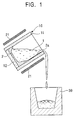
- FIG. 1 shows a tilt-tapping method by which the melt is tapped by tilting the whole crucible.
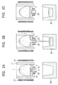
- FIG. 2 shows a bottom-tapping method by which the melt is tapped from a nozzle attached at the bottom of the crucible.
- FIG. 3 shows a bottom-tapping method in a levitation type cold crucible.
- the solidified skull 2 Since the solidified skull 2 is markedly grown due to increased contact area between the melt 1 and the side wall 11 of the crucible due to tilting of the crucible unit (crucible 10 and melting coil 21 ) during tapping in the tapping method shown by the reference numeral 2a in FIG. 1, the amount of tapped melt is accordingly decreased. Therefore, it is desirable in the tilt-tapping method to tap the melt as soon as possible to shorten the residence time of the melt in the crucible while it is tilted.
- the overall melt should be tapped within several seconds by a momentary tilting.
- tapping is once halted in this tapping method, the contact area between the melt and the wall of the crucible becomes so large while the crucible unit remains to be tilted that the solidified skull is markedly grown. Therefore, the solidified skull 2a should be melted again for resuming tapping after returning the tilted crucible to its original position, requiring much time for resuming tapping after the halt of tapping.
- a melting subject is melted by allowing it to contact with the bottom and inner wall of a crucible while forming a solidified skull 2 on the surface of the melting subject, followed by allowing a nozzle tap 3 disposed at the top of a tapping nozzle 13 to melt with a melting coil (operated at, for example, 1800 kW and 1 kHz) 21 and a tapping coil (operated at, for example, 400 kW and 4 kHz) 22 for tapping. Since the tapping rate in this method is proportional to the square root of the height from the nozzle hole to the surface of the melt (the height of melt surface), the tapping rate will be decreased as tapping is proceeded to reduce the height of the melt surface.
- a high frequency coil (operating at, for example, 1000 kW and 30 kHz) is used for the upper melting induction coil 25 and a relatively low frequency coil (operating at, for example, 1000 kW and 3 kHz) as compared with the induction coil described above is used in order to endow the lower induction coil 26 with a large levitation force for melting the metal while allowing it to float. Since it is difficult, however, in the levitation type cold crucible induction melting apparatus to float a large quantity of molten metal, a melting apparatus merely available for about 50 kg of the melting subject is currently operating and the apparatus has not been applied for industrial scale production.
- the object of the present invention carried out by noticing the foregoing problems is to provide a melting method by which melting materials having various configurations are collectively melted to adjust the composition in the melt, thereby obtaining a highly pure and homogeneous melt in an industrial scale while providing a melting apparatus and a tapping method by developing a method for aggressively controlling the tapping rate for simplifying application of the tapping method to various casting method such as a continuous casting method by tapping at a constant rate, wherein the tapping can be halted on the way of tapping besides enabling tapping to resume within a short period of time.
- the present invention has the following constructions for attaining the foregoing objects.
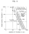
- the present invention provides a melting method using a cold crucible induction melting apparatus provided with a melting coil wound around the circumference of the crucible made of a conductive metal wherein, by using a crucible with an inner diameter of 400 mm or more, a solid phase area comprising a solidified mass of a melting subject itself is formed on the bottom of the crucible, the melting subject being melted by flowing through the melting coil an electric current represented by the following equation while allowing the melt to be held on the solid phase: 7.8 - 2 ⁇ log(D) ⁇ log(F) ⁇ 8.7 - 2 ⁇ log(D) (wherein F denotes the frequency of a power supply and D denotes the inner diameter (mm) of the crucible)
- the present invention also provides a method for tapping the melt prepared in the method described above, wherein a tapping nozzle is attached at the bottom of the crucible while winding a tapping coil around the circumference of the tapping nozzle, and the skull solidified in the tapping nozzle is tapped after heat-melting by flowing an electric current through the tapping coil.
- the present invention provides a tapping method using the cold crucible induction melting apparatus, wherein the tapping rate is controlled by detecting the height of the melt surface and controlling the height of the melt surface by the controlling the electric current through the melting coil depending on the height of the melt surface.
- the present invention provides a tapping method for controlling the tapping rate to be constant by maintaining the melt surface at a constant level.
- the present invention provides a tapping method using the cold crucible induction melting apparatus, wherein the melt in the tapping nozzle is solidified for halting tapping by reducing the amount of the electric current (including to halt the electric current) through the tapping coil, and tapping is resumed by allowing the solid phase in the tapping nozzle to melt by increasing the amount of the electric current through the tapping coil.
- the present invention provides a cold crucible induction melting apparatus in which a coil is wound around a crucible unit having a tapping nozzle at the bottom of the crucible, a coil being also wound around the tapping nozzle, wherein a wide upper introduction gate and a narrow lower discharge port are provided at the tapping nozzle while allowing the amount of the electric current through the tapping coil so as to be able to control for increasing or decreasing it.
- the present invention provides a cold crucible induction melting apparatus, wherein a tapered face is provided at the circumference wall on the way from the upper introduction gate to the lower discharge port along the direction to close the flow path.
- the present invention provides a cold crucible induction melting apparatus, wherein an insulation coating film is formed on the inner surface of the tapping nozzle.
- the present invention also provides titanium and a titanium alloy produced by using the cold crucible induction melting apparatus described above.
- Fig. 1 shows an illustrative drawing indicating an example of tapping from a cold crucible induction melting apparatus using a tilting method (a conventional method).
- FIG. 2A through FIG. 2C are illustrative drawings showing an example of bottom tapping by conventional cold crucible melting, wherein FIG. 2A denotes before the start of tapping, FIG. 2B denotes during tapping and FIG. 2C denotes that resuming of tapping is impossible.
- FIG. 3 shows an illustrative drawing indicating an example of bottom tapping in a levitation type cold crucible melting apparatus (a conventional method).
- FIG. 4 shows a schematic chart of a melt-casting method according to one embodiment of the present invention.
- FIG. 5 shows a relation between the diameter of the melting crucible according to the present invention and the power supply frequency.
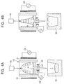
- FIG. 6A and FIG. 6B show an illustrative drawings of a cold crucible melting and bottom tapping apparatus in relation to the control method of the tapping rate according to the present invention, wherein FIG. 6A and FIG. 6B denote before the start of tapping and during the tapping, respectively.
- FIG. 7A and FIG. 7B show an illustrative drawing of a cold crucible melting and bottom tapping apparatus in relation to the tapping method and tapping resuming method according to the present invention, wherein FIG. 7A and FIG. 7B denote before the start of tapping and during the tapping, respectively.
- FIG. 8 shows a schematic illustrative drawing indicating the tapping nozzle of a cold crucible induction melting apparatus in which an insulation coating film according to the present invention has been formed.
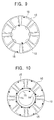
- FIG. 9 shows an illustrative drawing indicating the direction of an induction electric current (or a direction of a momentary electric current) in a conventional cold crucible induction melting apparatus.
- FIG. 10 an illustrative drawing indicating the direction of an induction electric current (or a direction of a momentary electric current) in a cold crucible induction melting apparatus according to the present invention.
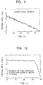
- FIG. 11 shows a graph indicating a time-dependent change of the tapping rate in a conventional example.
- FIG. 12 shows a graph indicating a time-dependent change of the tapping rate in an example according to the present invention.
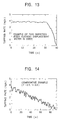
- FIG. 13 shows a graph indicating a time-dependent change of the tapping rate in an example according to the present invention.
- FIG. 14 shows a graph indicating a time-dependent change of the tapping rate in a comparative example.
- FIG. 15 shows a graph indicating a time-dependent change of the tapping rate in a comparative example.
- FIG. 4 shows a schematic drawing of the melting method according to the embodiments of the present invention.
- a melting raw material m is placed in a feed bucket 7 in a material chamber 4 to feed a prescribed amount of the raw material to a melting crucible 10 provided in a melting chamber 5 placed just under the bucket.
- a melting crucible 10 constructed by combining the plurality copper segments, which are rectangular or circular columns inside of which are water-cooled, and assembling into a vertical cylinder, and a bottom plate made of a copper material inside of which is cooled with water; an induction coil 21 provided so as to surround the periphery of the crucible 10 ; and a tapping nozzle 13 coupled to the bottom plate of the crucible 10 are provided in a melting chamber 5 .
- An evacuation mechanism 6 is connected to the melting chamber 5 .
- the melting raw material m supplied to the melting crucible 10 is melted by heating with an induction coil 21 in a reduced pressure atmosphere in the vacuum chamber evacuated with an evacuation mechanism 6 .
- a deoxidizer is added in the melting crucible 10 while maintaining the crucible in a vacuum of 133.322 ⁇ 10 -3 to 10 -4 Pa or in an inert gas atmosphere such as Ar.
- the raw material m melted in the melting crucible 10 is taken out of the tapping nozzle 13 and introduced into, for example, a mold 30 in a casting chamber provided just under the nozzle for casting, and the solidified material is taken out of the mold 30 as an ingot 31 .
- the tapping nozzle 13 are also constructed with water-cooled copper segment.
- the nozzle is provided with a tapping coil 22 wound around the periphery of the nozzle.
- the induction melting technique using the melting crucible 10 constructed with water-cooled copper is applicable to an industrial scale production using a crucible having an inner diameter of 400 mm or more even when the melting raw material m is a high-melting point metal.
- the melting method of interest in the present invention was practically carried out using experimental facilities equipped with a crucible having a diameter of 300 mm or less, to date the conditions required for a constant operation using a large industrial scale furnace have not been reported at all.
- the inventors of the present invention have proved that the large scale furnace may be successful in an industrial scale production by applying the method according to the present invention.
- the raw materials (the melting subjects) to be melted by the method according to the present invention are not especially limited, it is preferable to apply the method to metals and alloys containing as a principal component an active metallic element including titanium, zirconium, rare earth elements, silicon and aluminum; metals and alloys containing as a principal component a high melting point metallic element including chromium and vanadium; and metals and alloys containing iron, nickel and copper that require a ultra-high cleanness with a minimum amount of non-metallic contaminants, a remarkable effect being especially expected by applying the methods to metals and alloys containing as a principal component titanium such as melting of a titanium scrap.
- An alloy is produced forming a molten metal bath in a crucible comprising a water-cooled copper in the melting method according to the present invention, wherein the molten metal bath is held on a layer of a solid phase 2 (a solidified shell) made of a molten metal or alloy itself formed at the portion where the melt makes a contact with the bottom of the crucible.
- Melting can be continued while suppressing the peripheral side face of the molten metal bath from tightly contacting with the copper crucible while holding the peripheral side face of the molten metal bath by giving undulation with an electromagnetic force generated by a low-frequency electric current through the melting coil 21 .
- the frequency range should be appropriately determined for securely maintaining the undulation state as described above. In other words, when the frequency is too low, the molten metal bath is too vigorously agitated to largely disturb the molten metal bath, making the melt unstable by allowing it to readily make a contact with the crucible.
- the molten metal bath is too strongly agitated by the electromagnetic force that a part of the molten metal is solidified by making a contact with the water-cooled copper crucible, thereby further increasing the heat transfer from the melt to the copper crucible to make it difficult to maintain the molten metal bath itself.
- metals and alloys as a principal component an active metal element such as titanium, zirconium, a rare earth element, silicon and aluminum, metals and alloys containing as a principal component a high melting point metal element such as chromium and vanadium, and metals and alloys containing iron, nickel, cobalt and copper that requires an ultra-high cleanness with a minimum amount of non-metallic contaminants can be stably melted, when an appropriate frequency in the range determined by the equations (1) and (2), or a frequency in the range satisfying the following equation (3) (the range marked by parallel fine lines in FIG. 5): 7.8 - 2 ⁇ log(D) ⁇ log(F) ⁇ 8.7 - 2 ⁇ log(D)
- a layer of a solid phase (a solidified shell) of the molten metal or alloy is formed at an area where the melt makes a contact with the water-cooled crucible.
- the solid phase is left behind after the molten metal bath in the crucible has been tapped and the size of the solid phase is reduced to smaller than the inner diameter of the water-cooled copper crucible by contraction due to solidification with cooling. Accordingly, it is possible to take this solid phase out of the crucible after the melting work has been completed, or to insert the solid phase again in the water-cooled copper crucible before a separate melting run to heap up the melting material over the solid phase.
- the melting raw material filled in the water-cooled crucible usually has a bulk density of about 1/2 to 1/4 of the density of the melt, the volume of the material is reduced in the crucible by melting the charged melting material. Therefore, it is inevitable in the melting method according to the present invention to supplement the additional melting raw material.
- fluorides, chlorides and oxides that exhibit a smelting effect of the metallic melt simultaneously with melting or after the melt has been formed in melting the metal or alloy in the water-cooled copper crucible.
- fluoride include CaF 2 , BaF 2 , MgF 2 , NaF, KF and fluorides of the rare earth elements
- chloride examples include NaCl, KCl, CaCl 2 and MgCl 2
- oxide examples of the oxide include CaO, BaO, MgO, Na 2 O, SiO 2 and Al 2 O 3 .
- the melting subject melted by the method according to the present invention is taken out of the crucible by equipping the water-cooled copper crucible for use in melting with one or more of nozzles having water-cooled taps for tapping the molten metal at the bottom of the crucible or downward of the peripheral frame of the crucible.
- the construction described above enables the molten metal in the melting crucible to be tapped after removing the water-cooled tap by allowing the solid phase formed at the bottom or downward of the peripheral frame of the melting crucible to be melted by the heat ascribed to the molten metal itself.
- the tapping method described above involves some problems in controlling the tapping rate because the solidified layer is melted by the inherent heat of the melt. Therefore, it is preferable to use the tapping method as will be described below.
- the nozzle coupled with the water-cooled copper crucible has a basic construction resembling to the water-cooled copper crucible, which is composed of a plurality of rectangular or circular copper columns inside of which are cooled with water and outside of which are provided with a heating induction coil. Skull solidified in the nozzle is heat-melted to melt also the solidified layer formed in the water-cooled copper crucible by taking advantage of the inherent heat of the melt, thereby precisely controlling the tapping rate of the melt.
- the cold crucible induction melting apparatus and the tapping method according to the present invention is also provided in order to more precisely control the tapping rate according to the method as described above.
- a crucible 10 having a water-cooled copper segment structure is disposed at inside of the melting coil in the cold crucible induction melting apparatus shown in FIG. 6, and a tapping nozzle 13 comprising the water-cooled copper segment is disposed at the bottom center of the crucible.
- the tapping rate from the tapping nozzle disposed at the bottom of the crucible is in principle proportional to the height H (the height of the melt surface) from the nozzle port to the melt top surface, the tapping rate will be declined as the volume of the melt is decreased by tapping and the height of the melt surface is lowered.
- An electromagnetic force is applied to the melt along the centripetal direction due to the melting coil in the cold crucible induction melting apparatus, thereby the melt assuming a dome shape by being separated from the wall of the crucible.
- the dome rises up higher as the electric current flowing through the melting coil becomes larger, assuming a column-shaped melt when the centripetal force is extremely strong.
- the electromagnetic force working on the melt along the centripetal direction becomes in principle weaker as the distance between the melt and the wall of the crucible is longer when a given amount of the electric current is flowing through the melting coil.
- the height of the melt surface is therefore monitored at any time using a detecting apparatus 40 such as a laser displacement meter or an eddy current displacement meter throughout the tapping as shown in FIG. 6.
- a constant tapping rate can be obtained by keeping the height H of the melt surface at a constant level throughout the tapping period from the start of tapping as shown in FIG. 6A to the end of tapping as shown in FIG.
- I t+t' I t ⁇ (H 0 /H t+t' ) 1/n
- t denotes the time lapse (seconds) at an arbitrary moment during the measurement as measured from a reference time
- t' denotes an arbitrary time interval for controlling the electric current through the coil (a time interval for averaging the height of the melt surface)
- I t denotes the amount of the coil electric current (A) at an arbitrary moment during the measurement
- I t+t denotes the amount of the electric current (A) through the coil after a time lapse of t'
- H 0 denotes the height of the melt surface (mm) at the start of tapping
- H t+t' denotes the mean height of the melt surface (mm) during a time lapse of t'
- n being an lapse of the melt surface
- the height H of the melt surface is determined by a mean value in within a time interval of t' in the control equation (4) described above, because the melt is vigorously undulating by being affected by an agitating flow caused by the electromagnetic force to give a remarkable variation of the height of the melt surface every moment. Therefore, the amount of the coil electric current may be diverged by being synchronized with the undulation of the melt surface if the height of the melt surface is controlled using the momentary levels, thus requiring the height of the melt surface to be averaged throughput a given time interval.
- a time of 2.0 seconds or less is required.
- the electric current through the coil is not controlled by a reference electric current through the coil but is changed referring to the electric current through the coil before a time of t' to compensate decay of the electromagnetic force due to thinning of the melt, thereby enabling to control by setting the index n to 2.0 or larger.
- a crucible 10 comprising water-cooled copper segments are disposed at inside of the melting coil in the cold crucible induction melting apparatus shown in FIG. 7A and FIG. 7B, and the bottom of the crucible is so constructed as to have a flat and ring-shaped water cooled copper bottom plate 12 , a tapered member 13a and a straight member 13b , a tapping nozzle 13 having water-cooled copper segments being coupled to the bottom of the crucible.
- a nozzle tap 3 made of the same material as the raw material is placed in the tapping nozzle 13 for preventing the raw material (the melting subject) from falling off and the melt at the initial stage of melting from dripping.
- the raw material is placed in the crucible thereafter and is melted by flowing an electric current through the melting coil 21 (FIG. 7A).
- a high temperature is kept for a given time until the temperature of the melt and the shape of the solidified skull reaches to a stationary state after the raw material has been melted. Then, the nozzle tap 3 and the solidified skull layer on the nozzle tap 3 is melted by flowing an electric current through the tapping coil 22 to start tapping (FIG. 7B).
- the solidified skull is allowed to grow from the surface of the tapping nozzle by controlling the amount of the electric current through the tapping coil 22 to block the tapping nozzle 13 .
- a simplified method for halting tapping involves to reduce the amount of the electric current through the tapping coil, or the electric current to the tapping coil may be stopped.
- Whether halting of tapping is successful or not is determined by the amount of heat transfer from the melt and solidified skull to the bottom of the crucible 12 and the inner surface of the tapping nozzle 13 that are cooled with water cooled.
- the winding number of the coil per unit length on the tapered member 22 is increased while shortening the horizontal length from the coil to the inner surface of the tapered member for disposing the tapping coil so as to allow the coil to run along the tapered member 13a when the taper angle a is too small.
- a large amount of heat can be introduced to the solidified skull in the nozzle since consumption of the electric power at the tapping nozzle segments is reduced, heat transfer is rather increased due to increased surface area of the tapered member 13a or cooling area as the taper angle a is reduced, thereby making it impossible to tap the melt.
- the desirable taper angle ⁇ is therefore 70° or more.
- the taper angle ⁇ is too large, on the contrary, the winding number of the coil per unit length of the tapered member 22a of the coil is reduced and the horizontal distance from the tapping coil 22 to inner surface of the nozzle increases. Therefore, heat transfer at the tapered face of the nozzle is also made to exceed generated heat, rendering the solidified skull on the tapered face impossible to be melted and tapping becomes impossible. Therefore, the desirable taper angle is 100° or less.
- the angle at the tapered member is crucial in balancing heat transfer and heat generation.
- An angle of 70° or more and 100° or less is recommended and an angle in the range of 80° to 95° is more desirable.
- an insulation coating film 14 may be formed on the inner peripheral surface of the tapping nozzle 13 as shown in FIG. 8 in order to attain a stable tapping even when the inner diameter of the tapping nozzle is small.
- Heat generation in the cold crucible induction melting apparatus is naturally given by a Joule heat due to an induction electric current flowing through the solidified skull in the nozzle or through the melt, which is determined by the amount of the induction electric current.
- the water-cooled copper makes a pint contact with the solidified skull at a plurality of points due to contraction by solidification during the cooling process of the solidified skull and usually the solidified skull is substantially in an electrically insulted state from the copper wall.
- the solidified skull is gradually softened by temperature increase after starting an electric current to flow through the tapping coil since the solidified skull in the tapping nozzle should be melted for tapping using the tapping coil, thereby the point contact between the skull and the tapping nozzle turns to a face contact to form am electrical short circuit. Consequently, the induction current through the solidified skull flows along the direction indicated in FIG. 9, the induction current through the solidified skull being remarkably reduced because it immediately returns to the nozzle segments, thereby reducing the generated heat to render melting of the solidified skull impossible to inhibit tapping.
- the solidified skull and the melt are electrically insulated from the inner face of the nozzle, on the contrary, by forming an insulation coating film on the inner surface of the nozzle according to the present invention.
- the induction electric current does not return to the nozzle segments as shown in FIG. 10. Consequently, an induction current sufficient for melting the solidified skull can be secured to make tapping possible.
- the materials of the insulation coating film to be used in the present invention include metal oxides, metal carbides, metal nitrides and metal carbonitrides.
- the cold crucible induction melting apparatus is usually equipped in a vacuum chamber to mostly utilize for melting high melting point and active metals such as titanium. It is therefore desirable in the present invention to use a metal oxide as the material of the insulation coating film from the view point of stability at a high temperature and an inert property to the active metals, use of Al 2 O 3 , TiO 2 , CaO, Y 2 O 3 , ZrO 2 and the like being especially recommended.
- the method for forming the insulation coating film involves suspending the metal oxide in a liquid binder and coating the suspension on the inner surface of the tapping nozzle followed by evaporating the binder.
- the coating film can be less repeatedly used because the particles are so weakly bound with each other that the coating film is consumed by melting and tapping.
- the flame spray-coating methods include a gas flame spray-coating method and plasma flame spray-coating method, in which the metal oxide powder is melted in the high temperature and high speed gas flame or plasma flame and the molten metal oxide is allowed to collide with the coating object to solidify there.
- a strong coating film can be formed by this method, enabling the coating film to be repeatedly used without cracking, peeling and wear when the high melting point metals and active metals are melted and tapped.
- the film thickness is desirably 10 ⁇ m or more, more desirably 20 ⁇ m or more.
- the temperature on the surface of the insulation coating film becomes so close to the temperature of the solidified skull or the melt because the insulation film has a smaller heat conductivity than the material of the tapping nozzle, especially when the insulation coating film is composed of, for example, a metal oxide. Consequently, a remarkable temperature gradient as well as an accompanied heat stress appear in the coating film to readily generate cracks and partial peeling that are a kind of self-fracture of the coating film, thereby causing contamination of the melt. Accordingly, it is desirable that the film thickness is 500 ⁇ m or less.
- the desirable nozzle diameter is 4 mm or more, more desirably 10 mm or more.
- the desirable nozzle diameter is 100 mm or less, more desirably 50 mm or less.
- the ring-shaped water-cooled copper bottom plate 12 attached to the bottom of the crucible according to the present invention serves for shielding the electromagnetic wave emitted from the melting coil 22 and tapping coil 23 , thus preventing two power supplies of the low frequency power supply 23 for melting and high frequency power supply 24 for tapping from interfering with each other to cause malfunction and error.
- the materials of the crucible and tapping nozzle of the cold crucible induction melting apparatus are not limited to copper but other conductive materials may be used.
- the refrigerant is also not limited to water but any medium may be appropriately selected from a gas and liquid depending on its cooling ability.
- the melting and tapping operations are carried out in vacuum or under an inert gas atmosphere.
- a mold is provided under the tapping nozzle as shown in FIG. 4 and the tapped melt is solidified by injecting into the mold, thereby enabling an ingot to be readily and efficiently produced.
- a high purity metal and alloy can be continuously and efficiently casted by the steps comprising; injecting a molten metal tapped from the nozzle of the molten metal tapping bath into a water-cooled mold; allowing the melt to be solidified from the bottom side while maintaining the surface side to be melted; and pulling the ingot out of the mold at a speed corresponding to the injection rate of the molten metal, thereby enabling casting of the melt to be carried out in an industrial scale with a high purity and homogeneity. It is desirable for the melting raw material as hitherto described that the foregoing casting step is carried out in vacuum or under an inert gas atmosphere.
- Titanium and titanium alloys are obtained in an industrial scale with a high purity and high homogeneity as described above since they are produced by using the cold crucible induction melting apparatus according to the present invention.
- the temperature of the melt in the casting step is lower than the casting temperature in producing conventional cast metals, because the melt is tapped through the water-cooled copper nozzle provided for tapping at the bottom of the melting crucible when titanium and titanium alloys are produced with the apparatus according to the present invention, thereby the solidification time is shortened to make the texture of the ingot fine and uniform, hardly causing any shrinkage cavities.
- Melting crucibles 10 with an inner diameter of 430 mm and 530 mm, respectively, are constructed with a plurality of rectangular copper columns inside of which is cooled with water.
- a melting coils 21 made of water-cooled copper is provide at outside of the melting crucible.
- a melting chamber 5 is constructed by accommodating the crucible and coil in a vacuum chamber. Melting tests of titanium, chromium and carbon steel were carried out using a melting chamber 5 .
- the ranges of the power supply frequencies were calculated to be 340 to 2700 Hz and 225 to 1780 Hz for the melting crucibles with inner diameters of 530 mm and 430 mm, respectively, from the equation (3).
- a power supply with a frequency of about 1000 Hz or 500 Hz was used for the melting crucible with an inner diameter of 430 mm while a power supply with a frequency of about 800 Hz or 400 Hz was used for the melting crucible with an inner diameter of 530 mm.
- tapping from the bottom of the crucible is possible by a combination of a graphite crucible with a diameter of 5 to 100 mm and a water-cooled tap. It was also confirmed that tapping is possible by using a high frequency power supply with a frequency in the range of 5 to 20 kHz in a combination of a water-cooled nozzle and tapping coil.
- slugs such as CaF 2 , BaF 2 , CaO and SiO 2 were added in a proportion of 5% by weight of the melt to allow the slugs to melt by the heat of the metal bath
- a slag bath was formed in the vicinity of the upper wall of the crucible in the metal bath.
- a variety of smelting effects may be expected using the slug bath. It is possible to selectively take out the metal bath by leaving the slag bath behind by allowing the metal bath to tap from the bottom of the crucible, since the slag bath is formed at the upper wall side of the metal bath.
- a tapping nozzle with an inner diameter of 20 mm was provided at the bottom of a cold crucible melting furnace equipped with a crucible with an inner diameter of 400 mm. Melted and held by a high frequency power supply for melting was 200 kg of titanium, and a high frequency power supply for tapping was turned on after the melt temperature and solidified skull configuration had been stabilized to tap at an output power of 200 kw.
- the time-dependent tapping rate is shown in FIG. 11.
- the horizontal axis of the graph in FIG. 11 denotes the amount of tapping per one second. It can be understood that the tapping rate in the conventional example was decreased with time as shown in the graph.
- Nozzles having various configurations (nozzle angle and nozzle diameter) as shown in TABLE 2 were provided at the bottom of a cold crucible induction melting apparatus equipped with a crucible with an inner diameter of 400 mm. Tapping, halting of tapping and possibility to resume tapping as well as the time required for each operations were investigated. The results are listed in TABLE 2.
- 200 kg of titanium was melted with a coil output of 1600 kW and, after the temperature of the melt and the shape of the skull had reached to a stationary state, an electric current was started to flow through the tapping coil.
- the tapping initiation time was defined to be the time interval from the start of electric current flow to the start of tapping.
- the halting time of tapping in TABLE 2 refers to the time interval from the moment when the electric current has been turned off to the moment when tapping has been halted. Melting was resumed thereafter at a melting coil output of 1600 kW. When the temperature of the melt and the configuration of the solidified skull had reached to a stationary state, an electric current was started to flow again through the tapping coil.
- the resume time of tapping is defined to be the time interval from moment when the electric current flow has been resumed to the moment when tapping has been resumed. While the power output for the tapping coil is not uniform since it changes depending on the configuration of the nozzle, a maximum output available was impressed in this example using the same high frequency power supply throughout the experiment.
- the sample Nos. 1 to 6 denote the experimental results when the angle of the tapered nozzle member was changed in a range of 60° to 110° with a constant nozzle diameter of 20 mm.
- the power output of the tapping coil became large when the taper angle is 60° or less (No. 1), the solidified skull in the nozzle could not be melted since the surface area of the tapered member, or the cooling area, was increased due to smaller taper angle to render tapping impossible.
- Tapping was also impossible when the taper angle was 110° or more (No. 6) since the heat to be supplied to the taper face became small to render melting of the solidified skull on the taper face impossible.
- the time required for start of tapping, halt of tapping and resume of tapping were the shortest at a nozzle taper angle of 90° (No. 4), indicating that the nozzle has an excellent control ability.
- the sample Nos. 7 to 16 denote the results when the nozzle diameters were changed in a range from 3 to 110 mm with a constant taper angle of 90°.
- the nozzle diameter was 3 mm (No. 10)
- tapping was impossible due to the actions of the electromagnetic force and surface tension.
- the nozzle diameter was 110 mm (No. 16)
- tapping was possible but resume of tapping was impossible because the solidified skull could not be grown due to large tapping flow rate.
- the sample Nos. 17 to 20 denote the examples of tapping using conventional nozzles (not tapered), in which halt of tapping was impossible at a nozzle diameter of 40 mm or more because nozzles could not be blocked since the solidified skull could not be grown at the straight nozzle member due to a weak contact of the solidified skull with the inner surface of the nozzle but the solidified skull was grown merely at the bottom of the crucible. Melting of the solidified skull and tapping of the melt were also impossible when the nozzle diameter was 25 mm or less because the distance between the tapping coil and the solidified skull at upward of the nozzle port was so remote that the heat required for melting could not be supplied to the skull.
- the sample Nos. 21 to 24 denote conventional examples. While tapping was possible at an electric power of 1200 kW using a nozzle having a wide inner diameter of 40 mm or more, tapping was impossible at 1200 kW with a tapping nozzle having an inner diameter of 30 mm or less.
- the sample Nos. 25 to 33 correspond to the examples of the present invention, in which a various kind of insulation coating films were formed by a plasma flame spray-coating. Tapping was possible at a melting electric power of 1200 kW. Tapping was also possible without any cracks, peeling and wear of the insulation coating film when Al 2 O 3 , TiO 2 , CaO, Y 2 O 3 and ZrO 2 were used as a pure compound or as a mixture thereof.
- the insulation coating film was partly peeled off at the first melting and tapping to render tapping impossible at the fourth run and thereafter.
- At least 20 times of melting and tapping were possible in the sample No. 42 in which the insulation coating film was formed by a gas flame spray-coating method, although cracks and peeling were observed at the 15th run, proving that the method was practically applicable.
- the plasma flame spray-coating method No. 23
- few cracks and peeling of the coating film were observed after the 50 times of melting and tapping, making it possible to melt and tap without any contamination.
- the coating films were partly peeled off by several times of uses in the sample Nos. 51 and 52 having too thin insulation coating films, scores of repeated uses were possible in the sample Nos. 53 to 56 having the insulation coating films with a thickness of 20 ⁇ m or more.
- the insulation coating film is too thick as in the sample Nos. 57, and 58, on the other hand, cracks and peeling of the coating films were observed after several times of uses to contaminate the films.
- the present invention constructed as hitherto described allows the cold crucible induction melting apparatus to collectively melt the melting raw material having various configurations while enabling the composition to be adjusted in the melt, thus making a mass production of highly pure and homogeneous metals and alloys possible in an industrial scale.
- the tapping rate can be aggressively controlled in tapping after melting, allowing the method to be readily applied to various casting processes such as a continuous casting besides enabling casting to be halted on its way, thus providing a melting apparatus and tapping method that can resume tapping within a short period of time.
- the present invention provides a melting method by which the melting raw materials having a variety of configurations are collectively melted to enable the composition to be adjusted in the melt, and a melting apparatus and tapping method by which tapping is readily controlled, wherein the raw materials are melted by flowing an electric current satisfying the frequency range defined by the equation below using a crucible with an inner diameter of 400 mm or more in melting using a cold crucible induction melting apparatus, the melt being tapped through a tapping nozzle provided at the bottom of the crucible and equipped with a tapping coil wound around the circumference of the nozzle: 7.8 ⁇ 2 ⁇ log(D) ⁇ log (F) ⁇ 8.7 - 2 ⁇ log(D) (wherein F denotes the frequency of a power supply and D denotes the inner diameter (mm) of the crucible)
Landscapes
- Engineering & Computer Science (AREA)
- Chemical & Material Sciences (AREA)
- Mechanical Engineering (AREA)
- Metallurgy (AREA)
- Manufacturing & Machinery (AREA)
- Materials Engineering (AREA)
- Organic Chemistry (AREA)
- Geology (AREA)
- General Life Sciences & Earth Sciences (AREA)
- Environmental & Geological Engineering (AREA)
- Life Sciences & Earth Sciences (AREA)
- General Engineering & Computer Science (AREA)
- Crucibles And Fluidized-Bed Furnaces (AREA)
- Manufacture And Refinement Of Metals (AREA)
Applications Claiming Priority (6)
| Application Number | Priority Date | Filing Date | Title |
|---|---|---|---|
| JP7435199A JP2000274951A (ja) | 1999-03-18 | 1999-03-18 | コールドクルーシブル誘導溶解装置及びその出湯方法 |
| JP11074352A JP2000268948A (ja) | 1999-03-18 | 1999-03-18 | コールドクルーシブル誘導溶解装置の出湯方法 |
| JP7435199 | 1999-03-18 | ||
| JP7435299 | 1999-03-18 | ||
| JP11212542A JP2001041661A (ja) | 1999-07-27 | 1999-07-27 | コールドクルーシブル誘導溶解装置 |
| JP21254299 | 1999-07-27 |
Publications (3)
| Publication Number | Publication Date |
|---|---|
| EP1045216A2 true EP1045216A2 (fr) | 2000-10-18 |
| EP1045216A3 EP1045216A3 (fr) | 2003-03-05 |
| EP1045216B1 EP1045216B1 (fr) | 2006-05-03 |
Family
ID=27301478
Family Applications (1)
| Application Number | Title | Priority Date | Filing Date |
|---|---|---|---|
| EP99119405A Expired - Lifetime EP1045216B1 (fr) | 1999-03-18 | 1999-09-28 | Méthode pour la fusion par induction dans une installation à creuset froid |
Country Status (3)
| Country | Link |
|---|---|
| US (1) | US6144690A (fr) |
| EP (1) | EP1045216B1 (fr) |
| DE (1) | DE69931141T2 (fr) |
Cited By (8)
| Publication number | Priority date | Publication date | Assignee | Title |
|---|---|---|---|---|
| FR2837111A1 (fr) * | 2002-03-14 | 2003-09-19 | Boeing Co | Filtre pour filtrer des inclusions alpha dures des alliages metalliques actifs en fusion, systeme comportant ce filtre et equipement comportant ce systeme |
| EP2022294A2 (fr) * | 2006-05-30 | 2009-02-11 | Howmet Corporation | Procede de fusion utilisant un recipient de fusion en graphite |
| WO2013183031A1 (fr) * | 2012-06-08 | 2013-12-12 | Imp Automation (Pty) Ltd | Système et procédé de séparation |
| WO2014051919A3 (fr) * | 2012-09-28 | 2014-05-30 | General Electric Company | Procédés et systèmes pour unir des matériaux |
| US9764380B2 (en) | 2013-02-04 | 2017-09-19 | Almex USA, Inc. | Process and apparatus for direct chill casting |
| US9849507B2 (en) | 2012-05-17 | 2017-12-26 | Almex USA, Inc. | Process and apparatus for minimizing the potential for explosions in the direct chill casting of aluminum lithium alloys |
| US9936541B2 (en) | 2013-11-23 | 2018-04-03 | Almex USA, Inc. | Alloy melting and holding furnace |
| WO2023052161A1 (fr) * | 2021-09-28 | 2023-04-06 | Ald Vacuum Technologies Gmbh | Dispositif et procédé pour la production d'un composant de moulage à la cire perdue |
Families Citing this family (23)
| Publication number | Priority date | Publication date | Assignee | Title |
|---|---|---|---|---|
| JP4147604B2 (ja) * | 1997-04-23 | 2008-09-10 | 神鋼電機株式会社 | 誘導加熱溶解炉およびその底部出湯機構 |
| US6385230B1 (en) | 2001-03-14 | 2002-05-07 | Floswerve Manage Company | Homogeneous electrode of a reactive metal alloy for vacuum arc remelting and a method for making the same from a plurality of induction melted charges |
| DE10156336A1 (de) * | 2001-11-16 | 2003-06-05 | Ald Vacuum Techn Gmbh | Verfahren zur Herstellung von Legierungs-Ingots |
| TWI265198B (en) | 2002-12-02 | 2006-11-01 | Univ Nat Taiwan | The method and equipments for controlling the solidification of alloys in induction melting using cold crucible |
| US6993061B2 (en) * | 2003-11-07 | 2006-01-31 | Battelle Energy Alliance, Llc | Operating an induction melter apparatus |
| US7072378B2 (en) * | 2004-08-25 | 2006-07-04 | Battelle Energy Alliance, Llc | Induction heating apparatus and methods for selectively energizing an inductor in response to a measured electrical characteristic that is at least partially a function of a temperature of a material being heated |
| US7085305B2 (en) * | 2004-08-25 | 2006-08-01 | Battelle Energy Alliance, Llc | Induction heating apparatus and methods of operation thereof |
| JP2007019209A (ja) * | 2005-07-07 | 2007-01-25 | Sumco Solar Corp | 太陽電池用多結晶シリコンおよびその製造方法 |
| JP2007152386A (ja) * | 2005-12-05 | 2007-06-21 | Japan Steel Works Ltd:The | 水素吸蔵合金およびその製造方法 |
| US8333230B2 (en) * | 2008-07-17 | 2012-12-18 | Battelle Energy Alliance, Llc | Casting methods |
| RU2403639C2 (ru) * | 2008-08-29 | 2010-11-10 | Институт ядерных исследований РАН (ИЯИ РАН) | Композиция материала мишени для получения радионуклидов и способ ее приготовления (варианты) |
| RU2393564C2 (ru) | 2008-09-12 | 2010-06-27 | Учреждение Российской Академии Наук Институт Ядерных Исследований Ран (Ияи Ран) | Мишень для получения радионуклидов и способ ее изготовления (варианты) |
| KR101218923B1 (ko) * | 2010-09-15 | 2013-01-04 | 한국수력원자력 주식회사 | 유도코일과 용융로 일체형 유도가열식 저온용융로 |
| JP5639548B2 (ja) | 2011-08-22 | 2014-12-10 | 株式会社神戸製鋼所 | チタン鋳塊の製造方法 |
| DE102012223904A1 (de) * | 2012-10-05 | 2014-04-10 | Continental Automotive Gmbh | Verfahren zum Herstellen eines elektronischen Hochstrom-Schaltkreises mittels Gasspritz-Technologie und Abdichten mit isolierendem Polymer |
| KR101457368B1 (ko) * | 2013-10-04 | 2014-11-03 | 한국수력원자력 주식회사 | 용융물의 유도가열식 배출장치 및 방법 |
| FR3044748B1 (fr) | 2015-12-03 | 2019-07-19 | Commissariat A L'energie Atomique Et Aux Energies Alternatives | Four a creuset froid a chauffage par deux inducteurs electromagnetiques, utilisation du four pour la fusion d'un melange de metal(ux) et d'oxyde(s) representatif d'un corium |
| US10383179B2 (en) * | 2016-12-06 | 2019-08-13 | Metal Industries Research & Development Centre | Crucible device with temperature control design and temperature control method therefor |
| CN107838423A (zh) * | 2017-12-12 | 2018-03-27 | 西安科技大学 | 一种电磁悬浮加热式3d打印机挤出喷头 |
| WO2019246255A1 (fr) * | 2018-06-20 | 2019-12-26 | Ultraflex International, Inc. | Système et procédé de fusion et de régulation de l'écoulement d'un métal fondu par une force électromagnétique à l'aide de multiples bobines d'induction |
| DE102018117300B3 (de) | 2018-07-17 | 2019-11-14 | Ald Vacuum Technologies Gmbh | Schwebeschmelzverfahren mit beweglichen Induktionseinheiten |
| FR3100421B1 (fr) | 2019-08-30 | 2021-09-10 | Commissariat Energie Atomique | Four à induction comprenant un circuit résonant additionnel |
| US11511337B2 (en) | 2019-12-31 | 2022-11-29 | Crystal Technologies LLC | Singulated liquid metal droplet generator |
Citations (5)
| Publication number | Priority date | Publication date | Assignee | Title |
|---|---|---|---|---|
| US5060914A (en) * | 1990-07-16 | 1991-10-29 | General Electric Company | Method for control of process conditions in a continuous alloy production process |
| EP0501153A1 (fr) * | 1991-02-01 | 1992-09-02 | General Electric Company | Assemblage de tuyère pour production continue d'alliages et procédé d'obtention |
| US5280496A (en) * | 1990-07-26 | 1994-01-18 | Francois Schlecht | Induction furnace with cooled crucible |
| US5479438A (en) * | 1993-06-23 | 1995-12-26 | Leybold Durferrit Gmbh | Apparatus for fusing a solid layer of electrically conductive material |
| EP0874206A1 (fr) * | 1997-04-23 | 1998-10-28 | Shinko Electric Co. Ltd. | Four à induction et mécanisme pour la coulée par le fond |
Family Cites Families (13)
| Publication number | Priority date | Publication date | Assignee | Title |
|---|---|---|---|---|
| DE4018925A1 (de) * | 1990-06-13 | 1991-12-19 | Leybold Ag | Induktionsschmelzofen |
| US5160532A (en) * | 1991-10-21 | 1992-11-03 | General Electric Company | Direct processing of electroslag refined metal |
| JP2967092B2 (ja) * | 1991-12-20 | 1999-10-25 | 科学技術庁金属材料技術研究所長 | 浮上溶解装置 |
| US5348566A (en) * | 1992-11-02 | 1994-09-20 | General Electric Company | Method and apparatus for flow control in electroslag refining process |
| US5310165A (en) * | 1992-11-02 | 1994-05-10 | General Electric Company | Atomization of electroslag refined metal |
| US5332197A (en) * | 1992-11-02 | 1994-07-26 | General Electric Company | Electroslag refining or titanium to achieve low nitrogen |
| FR2708725B1 (fr) * | 1993-07-29 | 1995-11-10 | Imphy Sa | Procédé de fusion d'un matériau électroconducteur dans un four de fusion par induction en creuset froid et four de fusion pour la mise en Óoeuvre de ce procédé. |
| US5366206A (en) * | 1993-12-17 | 1994-11-22 | General Electric Company | Molten metal spray forming atomizer |
| JP3129078B2 (ja) * | 1994-03-14 | 2001-01-29 | 富士電機株式会社 | 下穴出湯方式の浮揚溶解装置 |
| JP3305530B2 (ja) * | 1995-03-20 | 2002-07-22 | 中部電力株式会社 | 浮揚溶解装置 |
| US5889813A (en) * | 1995-08-25 | 1999-03-30 | Fuji Electric Co., Ltd | Levitation melting furnace |
| JP3769826B2 (ja) * | 1996-07-24 | 2006-04-26 | 富士電機システムズ株式会社 | 浮揚溶解装置 |
| JP2954896B2 (ja) * | 1997-01-09 | 1999-09-27 | 核燃料サイクル開発機構 | コールドクルーシブル誘導溶融炉からの溶融物抜き出し装置 |
-
1999
- 1999-09-21 US US09/400,995 patent/US6144690A/en not_active Expired - Lifetime
- 1999-09-28 EP EP99119405A patent/EP1045216B1/fr not_active Expired - Lifetime
- 1999-09-28 DE DE69931141T patent/DE69931141T2/de not_active Expired - Lifetime
Patent Citations (5)
| Publication number | Priority date | Publication date | Assignee | Title |
|---|---|---|---|---|
| US5060914A (en) * | 1990-07-16 | 1991-10-29 | General Electric Company | Method for control of process conditions in a continuous alloy production process |
| US5280496A (en) * | 1990-07-26 | 1994-01-18 | Francois Schlecht | Induction furnace with cooled crucible |
| EP0501153A1 (fr) * | 1991-02-01 | 1992-09-02 | General Electric Company | Assemblage de tuyère pour production continue d'alliages et procédé d'obtention |
| US5479438A (en) * | 1993-06-23 | 1995-12-26 | Leybold Durferrit Gmbh | Apparatus for fusing a solid layer of electrically conductive material |
| EP0874206A1 (fr) * | 1997-04-23 | 1998-10-28 | Shinko Electric Co. Ltd. | Four à induction et mécanisme pour la coulée par le fond |
Cited By (18)
| Publication number | Priority date | Publication date | Assignee | Title |
|---|---|---|---|---|
| FR2837111A1 (fr) * | 2002-03-14 | 2003-09-19 | Boeing Co | Filtre pour filtrer des inclusions alpha dures des alliages metalliques actifs en fusion, systeme comportant ce filtre et equipement comportant ce systeme |
| EP2022294A2 (fr) * | 2006-05-30 | 2009-02-11 | Howmet Corporation | Procede de fusion utilisant un recipient de fusion en graphite |
| EP2022294A4 (fr) * | 2006-05-30 | 2014-04-16 | Howmet Corp | Procede de fusion utilisant un recipient de fusion en graphite |
| US9895744B2 (en) | 2012-05-17 | 2018-02-20 | Almex USA, Inc. | Process and apparatus for direct chill casting |
| US10946440B2 (en) | 2012-05-17 | 2021-03-16 | Almex USA, Inc. | Process and apparatus for minimizing the potential for explosions in the direct chill casting aluminum alloys |
| US10646919B2 (en) | 2012-05-17 | 2020-05-12 | Almex USA, Inc. | Process and apparatus for direct chill casting |
| US9849507B2 (en) | 2012-05-17 | 2017-12-26 | Almex USA, Inc. | Process and apparatus for minimizing the potential for explosions in the direct chill casting of aluminum lithium alloys |
| WO2013183031A1 (fr) * | 2012-06-08 | 2013-12-12 | Imp Automation (Pty) Ltd | Système et procédé de séparation |
| WO2014051919A3 (fr) * | 2012-09-28 | 2014-05-30 | General Electric Company | Procédés et systèmes pour unir des matériaux |
| CN104870134A (zh) * | 2012-09-28 | 2015-08-26 | 通用电气公司 | 用于结合材料的方法和系统 |
| US9950360B2 (en) | 2013-02-04 | 2018-04-24 | Almex USA, Inc. | Process and apparatus for minimizing the potential for explosions in the direct chill casting of lithium alloys |
| US9764380B2 (en) | 2013-02-04 | 2017-09-19 | Almex USA, Inc. | Process and apparatus for direct chill casting |
| US10864576B2 (en) | 2013-02-04 | 2020-12-15 | Almex USA, Inc. | Process and apparatus for minimizing the potential for explosions in the direct chill casting of lithium alloys |
| US9936541B2 (en) | 2013-11-23 | 2018-04-03 | Almex USA, Inc. | Alloy melting and holding furnace |
| WO2015077527A3 (fr) * | 2013-11-23 | 2018-08-16 | Almex USA, Inc. | Four de fusion et de maintien d'un alliage |
| RU2716571C2 (ru) * | 2013-11-23 | 2020-03-12 | ОЛМЕКС ЮЭсЭй, ИНК. | Печь для плавки и выдерживания сплава |
| US10932333B2 (en) | 2013-11-23 | 2021-02-23 | Almex USA, Inc. | Alloy melting and holding furnace |
| WO2023052161A1 (fr) * | 2021-09-28 | 2023-04-06 | Ald Vacuum Technologies Gmbh | Dispositif et procédé pour la production d'un composant de moulage à la cire perdue |
Also Published As
| Publication number | Publication date |
|---|---|
| DE69931141T2 (de) | 2007-02-08 |
| EP1045216B1 (fr) | 2006-05-03 |
| DE69931141D1 (de) | 2006-06-08 |
| EP1045216A3 (fr) | 2003-03-05 |
| US6144690A (en) | 2000-11-07 |
Similar Documents
| Publication | Publication Date | Title |
|---|---|---|
| US6144690A (en) | Melting method using cold crucible induction melting apparatus | |
| US7967057B2 (en) | Induction melting apparatus employing halide type crucible, process for producing the crucible, method of induction melting, and process for producing ingot of ultrahigh-purity Fe-, Ni-, or Co-based alloy material | |
| US4915723A (en) | Apparatus for casting silicon with gradual cooling | |
| JP5048222B2 (ja) | 活性高融点金属合金の長尺鋳塊製造法 | |
| US7114548B2 (en) | Method and apparatus for treating articles during formation | |
| CN102471828A (zh) | 合金铸锭的制造方法 | |
| WO1990013377A1 (fr) | Filature en fusion a fond de moule refroidi par induction d'alliages metalliques reactifs | |
| US3771585A (en) | Device for melting sponge metal using inert gas plasmas | |
| JP3571212B2 (ja) | 金属・合金の溶解方法及び溶解鋳造方法 | |
| WO1989007499A1 (fr) | Procedes de surchauffage et de micro-alliage de metal fondu par contact avec un arc de plasma | |
| US3857696A (en) | Melting and casting of transitional metals and alloys | |
| JP2011173172A (ja) | 活性高融点金属合金の長尺鋳塊製造法 | |
| JP2006122920A (ja) | 活性高融点金属含有合金の長尺鋳塊製造法 | |
| JP5006161B2 (ja) | TiAl基合金の鋳塊製造方法 | |
| Sears | Current processes for the cold-wall melting of titanium | |
| US20080178705A1 (en) | Group IVB Metal Processing with Electric Induction Energy | |
| US5974075A (en) | Method of Magnetically-controllable, electroslag melting of titanium and titanium-based alloys and apparatus for carrying out same | |
| JP5342322B2 (ja) | 鋳塊の製造方法 | |
| JP2008018453A (ja) | 溶融金属の連続鋳造方法および連続鋳造用浸漬ランス | |
| JPH0531568A (ja) | プラズマ溶解鋳造方法 | |
| JP2001041661A (ja) | コールドクルーシブル誘導溶解装置 | |
| JP2000268948A (ja) | コールドクルーシブル誘導溶解装置の出湯方法 | |
| JP3233446B2 (ja) | 磁歪材料の製造装置および磁歪材料の製造方法 | |
| JP2003307390A (ja) | コールドクルーシブル溶解鋳造装置とその溶解鋳造方法 | |
| JPS6092432A (ja) | プラズマア−ク溶解方法および溶解装置 |
Legal Events
| Date | Code | Title | Description |
|---|---|---|---|
| PUAI | Public reference made under article 153(3) epc to a published international application that has entered the european phase |
Free format text: ORIGINAL CODE: 0009012 |
|
| 17P | Request for examination filed |
Effective date: 19990929 |
|
| AK | Designated contracting states |
Kind code of ref document: A2 Designated state(s): AT BE CH CY DE DK ES FI FR GB GR IE IT LI LU MC NL PT SE |
|
| AX | Request for extension of the european patent |
Free format text: AL;LT;LV;MK;RO;SI |
|
| PUAL | Search report despatched |
Free format text: ORIGINAL CODE: 0009013 |
|
| RIC1 | Information provided on ipc code assigned before grant |
Ipc: 7C 22B 9/00 B Ipc: 7F 27D 3/15 B Ipc: 7F 27B 14/06 B Ipc: 7F 27B 14/08 A |
|
| AK | Designated contracting states |
Kind code of ref document: A3 Designated state(s): AT BE CH CY DE DK ES FI FR GB GR IE IT LI LU MC NL PT SE Designated state(s): AT BE CH CY DE DK ES FI FR GB GR IE IT LI LU MC NL PT SE |
|
| AX | Request for extension of the european patent |
Extension state: AL LT LV MK RO SI |
|
| AKX | Designation fees paid |
Designated state(s): DE FR GB |
|
| 17Q | First examination report despatched |
Effective date: 20041001 |
|
| GRAP | Despatch of communication of intention to grant a patent |
Free format text: ORIGINAL CODE: EPIDOSNIGR1 |
|
| RTI1 | Title (correction) |
Free format text: MELTING METHOD USING COLD CRUCIBLE INDUCTION MELTING APPARATUS |
|
| GRAS | Grant fee paid |
Free format text: ORIGINAL CODE: EPIDOSNIGR3 |
|
| GRAA | (expected) grant |
Free format text: ORIGINAL CODE: 0009210 |
|
| RAP1 | Party data changed (applicant data changed or rights of an application transferred) |
Owner name: KABUSHIKI KAISHA KOBE SEIKO SHO (KOBE STEEL LTD.) |
|
| AK | Designated contracting states |
Kind code of ref document: B1 Designated state(s): DE FR GB |
|
| REG | Reference to a national code |
Ref country code: GB Ref legal event code: FG4D |
|
| REF | Corresponds to: |
Ref document number: 69931141 Country of ref document: DE Date of ref document: 20060608 Kind code of ref document: P |
|
| ET | Fr: translation filed | ||
| PLBE | No opposition filed within time limit |
Free format text: ORIGINAL CODE: 0009261 |
|
| STAA | Information on the status of an ep patent application or granted ep patent |
Free format text: STATUS: NO OPPOSITION FILED WITHIN TIME LIMIT |
|
| 26N | No opposition filed |
Effective date: 20070206 |
|
| REG | Reference to a national code |
Ref country code: FR Ref legal event code: PLFP Year of fee payment: 17 |
|
| PGFP | Annual fee paid to national office [announced via postgrant information from national office to epo] |
Ref country code: FR Payment date: 20150629 Year of fee payment: 17 |
|
| REG | Reference to a national code |
Ref country code: FR Ref legal event code: ST Effective date: 20170531 |
|
| PG25 | Lapsed in a contracting state [announced via postgrant information from national office to epo] |
Ref country code: FR Free format text: LAPSE BECAUSE OF NON-PAYMENT OF DUE FEES Effective date: 20160930 |
|
| PGFP | Annual fee paid to national office [announced via postgrant information from national office to epo] |
Ref country code: DE Payment date: 20180918 Year of fee payment: 20 |
|
| PGFP | Annual fee paid to national office [announced via postgrant information from national office to epo] |
Ref country code: GB Payment date: 20180926 Year of fee payment: 20 |
|
| REG | Reference to a national code |
Ref country code: DE Ref legal event code: R071 Ref document number: 69931141 Country of ref document: DE |
|
| REG | Reference to a national code |
Ref country code: GB Ref legal event code: PE20 Expiry date: 20190927 |
|
| PG25 | Lapsed in a contracting state [announced via postgrant information from national office to epo] |
Ref country code: GB Free format text: LAPSE BECAUSE OF EXPIRATION OF PROTECTION Effective date: 20190927 |