EP1042075B1 - Procede d'application de revetement en poudre - Google Patents
Procede d'application de revetement en poudre Download PDFInfo
- Publication number
- EP1042075B1 EP1042075B1 EP98960033A EP98960033A EP1042075B1 EP 1042075 B1 EP1042075 B1 EP 1042075B1 EP 98960033 A EP98960033 A EP 98960033A EP 98960033 A EP98960033 A EP 98960033A EP 1042075 B1 EP1042075 B1 EP 1042075B1
- Authority
- EP
- European Patent Office
- Prior art keywords
- substrate
- microns
- coating
- fluidised bed
- powder coating
- Prior art date
- Legal status (The legal status is an assumption and is not a legal conclusion. Google has not performed a legal analysis and makes no representation as to the accuracy of the status listed.)
- Expired - Lifetime
Links
- 239000000843 powder Substances 0.000 title claims abstract description 123
- 238000000576 coating method Methods 0.000 title claims abstract description 110
- 239000000758 substrate Substances 0.000 claims abstract description 138
- 239000002245 particle Substances 0.000 claims abstract description 104
- 238000000034 method Methods 0.000 claims abstract description 99
- 230000008569 process Effects 0.000 claims abstract description 95
- 239000011248 coating agent Substances 0.000 claims abstract description 82
- 239000008199 coating composition Substances 0.000 claims abstract description 66
- 238000007654 immersion Methods 0.000 claims abstract description 19
- 230000001464 adherent effect Effects 0.000 claims abstract description 9
- PNEYBMLMFCGWSK-UHFFFAOYSA-N aluminium oxide Inorganic materials [O-2].[O-2].[O-2].[Al+3].[Al+3] PNEYBMLMFCGWSK-UHFFFAOYSA-N 0.000 claims description 32
- 239000000203 mixture Substances 0.000 claims description 29
- 238000005243 fluidization Methods 0.000 claims description 22
- 239000000654 additive Substances 0.000 claims description 21
- 230000000996 additive effect Effects 0.000 claims description 13
- WNROFYMDJYEPJX-UHFFFAOYSA-K aluminium hydroxide Chemical compound [OH-].[OH-].[OH-].[Al+3] WNROFYMDJYEPJX-UHFFFAOYSA-K 0.000 claims description 11
- 229910021502 aluminium hydroxide Inorganic materials 0.000 claims description 11
- 229910052751 metal Inorganic materials 0.000 claims description 5
- 239000002184 metal Substances 0.000 claims description 5
- 238000010924 continuous production Methods 0.000 claims description 4
- 229920001187 thermosetting polymer Polymers 0.000 claims description 4
- 238000002156 mixing Methods 0.000 claims description 2
- 238000010888 cage effect Methods 0.000 abstract description 6
- 230000003047 cage effect Effects 0.000 abstract description 6
- 238000009503 electrostatic coating Methods 0.000 abstract description 2
- 230000015572 biosynthetic process Effects 0.000 abstract 1
- 238000009826 distribution Methods 0.000 description 44
- 239000010408 film Substances 0.000 description 34
- 239000000463 material Substances 0.000 description 26
- 239000003795 chemical substances by application Substances 0.000 description 21
- 229910000831 Steel Inorganic materials 0.000 description 20
- 239000010959 steel Substances 0.000 description 20
- 230000008021 deposition Effects 0.000 description 19
- 229920000647 polyepoxide Polymers 0.000 description 18
- ISAOCJYIOMOJEB-UHFFFAOYSA-N benzoin Chemical compound C=1C=CC=CC=1C(O)C(=O)C1=CC=CC=C1 ISAOCJYIOMOJEB-UHFFFAOYSA-N 0.000 description 16
- 239000003822 epoxy resin Substances 0.000 description 16
- 229920000728 polyester Polymers 0.000 description 15
- 230000005684 electric field Effects 0.000 description 13
- 238000002474 experimental method Methods 0.000 description 10
- 239000007789 gas Substances 0.000 description 10
- 239000000049 pigment Substances 0.000 description 10
- 229920001225 polyester resin Polymers 0.000 description 10
- 239000004645 polyester resin Substances 0.000 description 10
- 229920000178 Acrylic resin Polymers 0.000 description 9
- 239000004925 Acrylic resin Substances 0.000 description 9
- VYPSYNLAJGMNEJ-UHFFFAOYSA-N Silicium dioxide Chemical compound O=[Si]=O VYPSYNLAJGMNEJ-UHFFFAOYSA-N 0.000 description 9
- GWEVSGVZZGPLCZ-UHFFFAOYSA-N Titan oxide Chemical compound O=[Ti]=O GWEVSGVZZGPLCZ-UHFFFAOYSA-N 0.000 description 9
- 239000004615 ingredient Substances 0.000 description 9
- 239000004593 Epoxy Substances 0.000 description 8
- 244000028419 Styrax benzoin Species 0.000 description 8
- 235000000126 Styrax benzoin Nutrition 0.000 description 8
- 235000008411 Sumatra benzointree Nutrition 0.000 description 8
- 229960002130 benzoin Drugs 0.000 description 8
- 230000000694 effects Effects 0.000 description 8
- 239000000945 filler Substances 0.000 description 8
- 235000019382 gum benzoic Nutrition 0.000 description 8
- 229920000642 polymer Polymers 0.000 description 8
- 239000004411 aluminium Substances 0.000 description 7
- 229910052782 aluminium Inorganic materials 0.000 description 7
- XAGFODPZIPBFFR-UHFFFAOYSA-N aluminium Chemical compound [Al] XAGFODPZIPBFFR-UHFFFAOYSA-N 0.000 description 7
- IJGRMHOSHXDMSA-UHFFFAOYSA-N Atomic nitrogen Chemical compound N#N IJGRMHOSHXDMSA-UHFFFAOYSA-N 0.000 description 6
- 239000011230 binding agent Substances 0.000 description 6
- IISBACLAFKSPIT-UHFFFAOYSA-N bisphenol A Chemical compound C=1C=C(O)C=CC=1C(C)(C)C1=CC=C(O)C=C1 IISBACLAFKSPIT-UHFFFAOYSA-N 0.000 description 6
- 239000003607 modifier Substances 0.000 description 6
- 229920005989 resin Polymers 0.000 description 6
- 239000011347 resin Substances 0.000 description 6
- 230000008901 benefit Effects 0.000 description 5
- OUPZKGBUJRBPGC-UHFFFAOYSA-N 1,3,5-tris(oxiran-2-ylmethyl)-1,3,5-triazinane-2,4,6-trione Chemical compound O=C1N(CC2OC2)C(=O)N(CC2OC2)C(=O)N1CC1CO1 OUPZKGBUJRBPGC-UHFFFAOYSA-N 0.000 description 4
- TZCXTZWJZNENPQ-UHFFFAOYSA-L barium sulfate Chemical compound [Ba+2].[O-]S([O-])(=O)=O TZCXTZWJZNENPQ-UHFFFAOYSA-L 0.000 description 4
- 238000010438 heat treatment Methods 0.000 description 4
- 239000012528 membrane Substances 0.000 description 4
- 230000003534 oscillatory effect Effects 0.000 description 4
- 230000035515 penetration Effects 0.000 description 4
- 239000000377 silicon dioxide Substances 0.000 description 4
- 239000007921 spray Substances 0.000 description 4
- WSFSSNUMVMOOMR-UHFFFAOYSA-N Formaldehyde Chemical compound O=C WSFSSNUMVMOOMR-UHFFFAOYSA-N 0.000 description 3
- LNEPOXFFQSENCJ-UHFFFAOYSA-N haloperidol Chemical compound C1CC(O)(C=2C=CC(Cl)=CC=2)CCN1CCCC(=O)C1=CC=C(F)C=C1 LNEPOXFFQSENCJ-UHFFFAOYSA-N 0.000 description 3
- 229910052734 helium Inorganic materials 0.000 description 3
- 239000001307 helium Substances 0.000 description 3
- SWQJXJOGLNCZEY-UHFFFAOYSA-N helium atom Chemical compound [He] SWQJXJOGLNCZEY-UHFFFAOYSA-N 0.000 description 3
- UQSXHKLRYXJYBZ-UHFFFAOYSA-N iron oxide Inorganic materials [Fe]=O UQSXHKLRYXJYBZ-UHFFFAOYSA-N 0.000 description 3
- 239000012948 isocyanate Substances 0.000 description 3
- 150000002513 isocyanates Chemical class 0.000 description 3
- 229910052757 nitrogen Inorganic materials 0.000 description 3
- 239000004033 plastic Substances 0.000 description 3
- 229920003023 plastic Polymers 0.000 description 3
- 230000000750 progressive effect Effects 0.000 description 3
- 230000009467 reduction Effects 0.000 description 3
- VTYYLEPIZMXCLO-UHFFFAOYSA-L Calcium carbonate Chemical compound [Ca+2].[O-]C([O-])=O VTYYLEPIZMXCLO-UHFFFAOYSA-L 0.000 description 2
- 239000004150 EU approved colour Substances 0.000 description 2
- LYCAIKOWRPUZTN-UHFFFAOYSA-N Ethylene glycol Chemical compound OCCO LYCAIKOWRPUZTN-UHFFFAOYSA-N 0.000 description 2
- 229920000877 Melamine resin Polymers 0.000 description 2
- 238000009825 accumulation Methods 0.000 description 2
- 239000002253 acid Substances 0.000 description 2
- 238000000429 assembly Methods 0.000 description 2
- -1 carboxy- Chemical class 0.000 description 2
- 239000003054 catalyst Substances 0.000 description 2
- 238000006243 chemical reaction Methods 0.000 description 2
- 150000001875 compounds Chemical class 0.000 description 2
- 230000007547 defect Effects 0.000 description 2
- QGBSISYHAICWAH-UHFFFAOYSA-N dicyandiamide Chemical compound NC(N)=NC#N QGBSISYHAICWAH-UHFFFAOYSA-N 0.000 description 2
- 125000005442 diisocyanate group Chemical group 0.000 description 2
- 239000010459 dolomite Substances 0.000 description 2
- 229910000514 dolomite Inorganic materials 0.000 description 2
- 239000000975 dye Substances 0.000 description 2
- 238000005516 engineering process Methods 0.000 description 2
- 238000001125 extrusion Methods 0.000 description 2
- 235000013980 iron oxide Nutrition 0.000 description 2
- WHIVNJATOVLWBW-UHFFFAOYSA-N n-butan-2-ylidenehydroxylamine Chemical compound CCC(C)=NO WHIVNJATOVLWBW-UHFFFAOYSA-N 0.000 description 2
- 229920003986 novolac Polymers 0.000 description 2
- 229940006093 opthalmologic coloring agent diagnostic Drugs 0.000 description 2
- 230000010355 oscillation Effects 0.000 description 2
- ISWSIDIOOBJBQZ-UHFFFAOYSA-N phenol group Chemical group C1(=CC=CC=C1)O ISWSIDIOOBJBQZ-UHFFFAOYSA-N 0.000 description 2
- 235000013824 polyphenols Nutrition 0.000 description 2
- 239000007787 solid Substances 0.000 description 2
- 239000003381 stabilizer Substances 0.000 description 2
- 239000000126 substance Substances 0.000 description 2
- 229920001169 thermoplastic Polymers 0.000 description 2
- 239000004416 thermosoftening plastic Substances 0.000 description 2
- LRXTYHSAJDENHV-UHFFFAOYSA-H zinc phosphate Chemical compound [Zn+2].[Zn+2].[Zn+2].[O-]P([O-])([O-])=O.[O-]P([O-])([O-])=O LRXTYHSAJDENHV-UHFFFAOYSA-H 0.000 description 2
- 229910000165 zinc phosphate Inorganic materials 0.000 description 2
- PCHXZXKMYCGVFA-UHFFFAOYSA-N 1,3-diazetidine-2,4-dione Chemical compound O=C1NC(=O)N1 PCHXZXKMYCGVFA-UHFFFAOYSA-N 0.000 description 1
- 125000000954 2-hydroxyethyl group Chemical group [H]C([*])([H])C([H])([H])O[H] 0.000 description 1
- QTWJRLJHJPIABL-UHFFFAOYSA-N 2-methylphenol;3-methylphenol;4-methylphenol Chemical compound CC1=CC=C(O)C=C1.CC1=CC=CC(O)=C1.CC1=CC=CC=C1O QTWJRLJHJPIABL-UHFFFAOYSA-N 0.000 description 1
- LHYQAEFVHIZFLR-UHFFFAOYSA-L 4-(4-diazonio-3-methoxyphenyl)-2-methoxybenzenediazonium;dichloride Chemical compound [Cl-].[Cl-].C1=C([N+]#N)C(OC)=CC(C=2C=C(OC)C([N+]#N)=CC=2)=C1 LHYQAEFVHIZFLR-UHFFFAOYSA-L 0.000 description 1
- GVNWZKBFMFUVNX-UHFFFAOYSA-N Adipamide Chemical compound NC(=O)CCCCC(N)=O GVNWZKBFMFUVNX-UHFFFAOYSA-N 0.000 description 1
- 229910000838 Al alloy Inorganic materials 0.000 description 1
- VYZAMTAEIAYCRO-UHFFFAOYSA-N Chromium Chemical compound [Cr] VYZAMTAEIAYCRO-UHFFFAOYSA-N 0.000 description 1
- 241000270722 Crocodylidae Species 0.000 description 1
- XZMCDFZZKTWFGF-UHFFFAOYSA-N Cyanamide Chemical compound NC#N XZMCDFZZKTWFGF-UHFFFAOYSA-N 0.000 description 1
- BRLQWZUYTZBJKN-UHFFFAOYSA-N Epichlorohydrin Chemical compound ClCC1CO1 BRLQWZUYTZBJKN-UHFFFAOYSA-N 0.000 description 1
- 239000004640 Melamine resin Substances 0.000 description 1
- 239000004952 Polyamide Substances 0.000 description 1
- NRCMAYZCPIVABH-UHFFFAOYSA-N Quinacridone Chemical compound N1C2=CC=CC=C2C(=O)C2=C1C=C1C(=O)C3=CC=CC=C3NC1=C2 NRCMAYZCPIVABH-UHFFFAOYSA-N 0.000 description 1
- 229920001807 Urea-formaldehyde Polymers 0.000 description 1
- KXBFLNPZHXDQLV-UHFFFAOYSA-N [cyclohexyl(diisocyanato)methyl]cyclohexane Chemical compound C1CCCCC1C(N=C=O)(N=C=O)C1CCCCC1 KXBFLNPZHXDQLV-UHFFFAOYSA-N 0.000 description 1
- PXAJQJMDEXJWFB-UHFFFAOYSA-N acetone oxime Chemical compound CC(C)=NO PXAJQJMDEXJWFB-UHFFFAOYSA-N 0.000 description 1
- NIXOWILDQLNWCW-UHFFFAOYSA-N acrylic acid group Chemical group C(C=C)(=O)O NIXOWILDQLNWCW-UHFFFAOYSA-N 0.000 description 1
- 238000013019 agitation Methods 0.000 description 1
- GZCGUPFRVQAUEE-SLPGGIOYSA-N aldehydo-D-glucose Chemical compound OC[C@@H](O)[C@@H](O)[C@H](O)[C@@H](O)C=O GZCGUPFRVQAUEE-SLPGGIOYSA-N 0.000 description 1
- 125000002723 alicyclic group Chemical group 0.000 description 1
- PYKYMHQGRFAEBM-UHFFFAOYSA-N anthraquinone Natural products CCC(=O)c1c(O)c2C(=O)C3C(C=CC=C3O)C(=O)c2cc1CC(=O)OC PYKYMHQGRFAEBM-UHFFFAOYSA-N 0.000 description 1
- 150000004056 anthraquinones Chemical class 0.000 description 1
- 230000003466 anti-cipated effect Effects 0.000 description 1
- IWLBIFVMPLUHLK-UHFFFAOYSA-N azane;formaldehyde Chemical compound N.O=C IWLBIFVMPLUHLK-UHFFFAOYSA-N 0.000 description 1
- 125000000751 azo group Chemical group [*]N=N[*] 0.000 description 1
- 230000004888 barrier function Effects 0.000 description 1
- ZXOATMQSUNJNNG-UHFFFAOYSA-N bis(oxiran-2-ylmethyl) benzene-1,3-dicarboxylate Chemical compound C=1C=CC(C(=O)OCC2OC2)=CC=1C(=O)OCC1CO1 ZXOATMQSUNJNNG-UHFFFAOYSA-N 0.000 description 1
- NEPKLUNSRVEBIX-UHFFFAOYSA-N bis(oxiran-2-ylmethyl) benzene-1,4-dicarboxylate Chemical compound C=1C=C(C(=O)OCC2OC2)C=CC=1C(=O)OCC1CO1 NEPKLUNSRVEBIX-UHFFFAOYSA-N 0.000 description 1
- 229910000019 calcium carbonate Inorganic materials 0.000 description 1
- 239000006229 carbon black Substances 0.000 description 1
- 230000015556 catabolic process Effects 0.000 description 1
- 230000008859 change Effects 0.000 description 1
- ZCDOYSPFYFSLEW-UHFFFAOYSA-N chromate(2-) Chemical compound [O-][Cr]([O-])(=O)=O ZCDOYSPFYFSLEW-UHFFFAOYSA-N 0.000 description 1
- 238000004140 cleaning Methods 0.000 description 1
- 239000003086 colorant Substances 0.000 description 1
- 239000004020 conductor Substances 0.000 description 1
- 238000005260 corrosion Methods 0.000 description 1
- 230000007797 corrosion Effects 0.000 description 1
- 229930003836 cresol Natural products 0.000 description 1
- 238000006731 degradation reaction Methods 0.000 description 1
- LNNWVNGFPYWNQE-GMIGKAJZSA-N desomorphine Chemical compound C1C2=CC=C(O)C3=C2[C@]24CCN(C)[C@H]1[C@@H]2CCC[C@@H]4O3 LNNWVNGFPYWNQE-GMIGKAJZSA-N 0.000 description 1
- KORSJDCBLAPZEQ-UHFFFAOYSA-N dicyclohexylmethane-4,4'-diisocyanate Chemical compound C1CC(N=C=O)CCC1CC1CCC(N=C=O)CC1 KORSJDCBLAPZEQ-UHFFFAOYSA-N 0.000 description 1
- GYZLOYUZLJXAJU-UHFFFAOYSA-N diglycidyl ether Chemical compound C1OC1COCC1CO1 GYZLOYUZLJXAJU-UHFFFAOYSA-N 0.000 description 1
- 238000007598 dipping method Methods 0.000 description 1
- 239000012777 electrically insulating material Substances 0.000 description 1
- 238000010894 electron beam technology Methods 0.000 description 1
- 150000002118 epoxides Chemical class 0.000 description 1
- 239000012530 fluid Substances 0.000 description 1
- 229920002313 fluoropolymer Polymers 0.000 description 1
- 239000004811 fluoropolymer Substances 0.000 description 1
- 238000009472 formulation Methods 0.000 description 1
- 229910021485 fumed silica Inorganic materials 0.000 description 1
- 229920001002 functional polymer Polymers 0.000 description 1
- 230000009477 glass transition Effects 0.000 description 1
- 125000004356 hydroxy functional group Chemical group O* 0.000 description 1
- WGCNASOHLSPBMP-UHFFFAOYSA-N hydroxyacetaldehyde Natural products OCC=O WGCNASOHLSPBMP-UHFFFAOYSA-N 0.000 description 1
- 230000001771 impaired effect Effects 0.000 description 1
- 239000001023 inorganic pigment Substances 0.000 description 1
- 238000003780 insertion Methods 0.000 description 1
- 230000037431 insertion Effects 0.000 description 1
- 230000003993 interaction Effects 0.000 description 1
- 150000002500 ions Chemical class 0.000 description 1
- 229910000398 iron phosphate Inorganic materials 0.000 description 1
- VBMVTYDPPZVILR-UHFFFAOYSA-N iron(2+);oxygen(2-) Chemical class [O-2].[Fe+2] VBMVTYDPPZVILR-UHFFFAOYSA-N 0.000 description 1
- WBJZTOZJJYAKHQ-UHFFFAOYSA-K iron(3+) phosphate Chemical compound [Fe+3].[O-]P([O-])([O-])=O WBJZTOZJJYAKHQ-UHFFFAOYSA-K 0.000 description 1
- JEIPFZHSYJVQDO-UHFFFAOYSA-N iron(III) oxide Inorganic materials O=[Fe]O[Fe]=O JEIPFZHSYJVQDO-UHFFFAOYSA-N 0.000 description 1
- BSIHWSXXPBAGTC-UHFFFAOYSA-N isoviolanthrone Chemical compound C12=CC=CC=C2C(=O)C2=CC=C3C(C4=C56)=CC=C5C5=CC=CC=C5C(=O)C6=CC=C4C4=C3C2=C1C=C4 BSIHWSXXPBAGTC-UHFFFAOYSA-N 0.000 description 1
- 238000002356 laser light scattering Methods 0.000 description 1
- MOUPNEIJQCETIW-UHFFFAOYSA-N lead chromate Chemical compound [Pb+2].[O-][Cr]([O-])(=O)=O MOUPNEIJQCETIW-UHFFFAOYSA-N 0.000 description 1
- 230000007774 longterm Effects 0.000 description 1
- 238000004519 manufacturing process Methods 0.000 description 1
- 238000005259 measurement Methods 0.000 description 1
- JDSHMPZPIAZGSV-UHFFFAOYSA-N melamine Chemical compound NC1=NC(N)=NC(N)=N1 JDSHMPZPIAZGSV-UHFFFAOYSA-N 0.000 description 1
- 239000003595 mist Substances 0.000 description 1
- OKRNLSUTBJUVKA-UHFFFAOYSA-N n,n,n',n'-Tetrakis(2-hydroxyethyl)adipamide Chemical compound OCCN(CCO)C(=O)CCCCC(=O)N(CCO)CCO OKRNLSUTBJUVKA-UHFFFAOYSA-N 0.000 description 1
- 239000012860 organic pigment Substances 0.000 description 1
- 150000002923 oximes Chemical class 0.000 description 1
- NFHFRUOZVGFOOS-UHFFFAOYSA-N palladium;triphenylphosphane Chemical compound [Pd].C1=CC=CC=C1P(C=1C=CC=CC=1)C1=CC=CC=C1.C1=CC=CC=C1P(C=1C=CC=CC=1)C1=CC=CC=C1.C1=CC=CC=C1P(C=1C=CC=CC=1)C1=CC=CC=C1.C1=CC=CC=C1P(C=1C=CC=CC=1)C1=CC=CC=C1 NFHFRUOZVGFOOS-UHFFFAOYSA-N 0.000 description 1
- IEQIEDJGQAUEQZ-UHFFFAOYSA-N phthalocyanine Chemical compound N1C(N=C2C3=CC=CC=C3C(N=C3C4=CC=CC=C4C(=N4)N3)=N2)=C(C=CC=C2)C2=C1N=C1C2=CC=CC=C2C4=N1 IEQIEDJGQAUEQZ-UHFFFAOYSA-N 0.000 description 1
- 239000004014 plasticizer Substances 0.000 description 1
- 229920002647 polyamide Polymers 0.000 description 1
- 150000008442 polyphenolic compounds Chemical class 0.000 description 1
- 239000012254 powdered material Substances 0.000 description 1
- 238000002360 preparation method Methods 0.000 description 1
- 238000002203 pretreatment Methods 0.000 description 1
- 230000001681 protective effect Effects 0.000 description 1
- 230000005855 radiation Effects 0.000 description 1
- 238000004064 recycling Methods 0.000 description 1
- 230000000717 retained effect Effects 0.000 description 1
- 230000002441 reversible effect Effects 0.000 description 1
- 238000007790 scraping Methods 0.000 description 1
- 238000000926 separation method Methods 0.000 description 1
- 239000008247 solid mixture Substances 0.000 description 1
- 239000010409 thin film Substances 0.000 description 1
- JOUDBUYBGJYFFP-FOCLMDBBSA-N thioindigo Chemical compound S\1C2=CC=CC=C2C(=O)C/1=C1/C(=O)C2=CC=CC=C2S1 JOUDBUYBGJYFFP-FOCLMDBBSA-N 0.000 description 1
- 239000004408 titanium dioxide Substances 0.000 description 1
- 239000000984 vat dye Substances 0.000 description 1
- 239000011800 void material Substances 0.000 description 1
- 239000008096 xylene Substances 0.000 description 1
Images


Classifications
-
- B—PERFORMING OPERATIONS; TRANSPORTING
- B05—SPRAYING OR ATOMISING IN GENERAL; APPLYING FLUENT MATERIALS TO SURFACES, IN GENERAL
- B05C—APPARATUS FOR APPLYING FLUENT MATERIALS TO SURFACES, IN GENERAL
- B05C19/00—Apparatus specially adapted for applying particulate materials to surfaces
- B05C19/02—Apparatus specially adapted for applying particulate materials to surfaces using fluidised-bed techniques
- B05C19/025—Combined with electrostatic means
-
- B—PERFORMING OPERATIONS; TRANSPORTING
- B05—SPRAYING OR ATOMISING IN GENERAL; APPLYING FLUENT MATERIALS TO SURFACES, IN GENERAL
- B05D—PROCESSES FOR APPLYING FLUENT MATERIALS TO SURFACES, IN GENERAL
- B05D1/00—Processes for applying liquids or other fluent materials
- B05D1/18—Processes for applying liquids or other fluent materials performed by dipping
- B05D1/22—Processes for applying liquids or other fluent materials performed by dipping using fluidised-bed technique
- B05D1/24—Applying particulate materials
-
- C—CHEMISTRY; METALLURGY
- C23—COATING METALLIC MATERIAL; COATING MATERIAL WITH METALLIC MATERIAL; CHEMICAL SURFACE TREATMENT; DIFFUSION TREATMENT OF METALLIC MATERIAL; COATING BY VACUUM EVAPORATION, BY SPUTTERING, BY ION IMPLANTATION OR BY CHEMICAL VAPOUR DEPOSITION, IN GENERAL; INHIBITING CORROSION OF METALLIC MATERIAL OR INCRUSTATION IN GENERAL
- C23C—COATING METALLIC MATERIAL; COATING MATERIAL WITH METALLIC MATERIAL; SURFACE TREATMENT OF METALLIC MATERIAL BY DIFFUSION INTO THE SURFACE, BY CHEMICAL CONVERSION OR SUBSTITUTION; COATING BY VACUUM EVAPORATION, BY SPUTTERING, BY ION IMPLANTATION OR BY CHEMICAL VAPOUR DEPOSITION, IN GENERAL
- C23C24/00—Coating starting from inorganic powder
-
- Y—GENERAL TAGGING OF NEW TECHNOLOGICAL DEVELOPMENTS; GENERAL TAGGING OF CROSS-SECTIONAL TECHNOLOGIES SPANNING OVER SEVERAL SECTIONS OF THE IPC; TECHNICAL SUBJECTS COVERED BY FORMER USPC CROSS-REFERENCE ART COLLECTIONS [XRACs] AND DIGESTS
- Y10—TECHNICAL SUBJECTS COVERED BY FORMER USPC
- Y10S—TECHNICAL SUBJECTS COVERED BY FORMER USPC CROSS-REFERENCE ART COLLECTIONS [XRACs] AND DIGESTS
- Y10S118/00—Coating apparatus
- Y10S118/05—Fluidized bed
Definitions
- This invention relates to a process for the application of powder coating compositions to substrates.
- Powder coatings form a rapidly growing sector of the coatings market.
- Powder coatings are solid compositions which are generally applied by an electrostatic spray process in which the powder coating particles are electrostatically charged by the spray gun and the substrate (normally metallic) is earthed.
- the charge on the powder coating particles is normally applied by interaction of the particles with ionised air (corona charging) or by friction (tribostatic or "tribo" charging).
- corona charging ionised air
- tribostatic or "tribo" charging tribostatic or "tribo” charging
- a disadvantage of this process is that there are difficulties in coating articles having complicated shapes, and especially articles having recessed portions, as a result of restricted access of the electric field lines into recessed locations (the Faraday cage effect), especially in the case of the relatively strong electric fields generated in the corona-charging process.
- the Faraday cage effect is much less evident in the case of tribostatic charging processes, but those processes have other drawbacks.
- powder coating compositions may be applied by fluidised-bed processes, in which the substrate workpiece is preheated (typically to 200°C-400°C) and dipped into a fluidised bed of the powder coating composition.
- the powder particles that come into contact with the preheated surface melt and adhere to the workpiece.
- the initially-coated workpiece may be subjected to further heating to complete the curing of the applied coating. Such post-heating may not be necessary in the case of thermoplastic powder coating compositions.
- Fluidised-bed processes eliminate the Faraday cage effect, thereby enabling recessed portions in the substrate workpiece to be coated, and are attractive in other respects, but have the well-known disadvantage that the applied coatings are substantially thicker than those obtainable by electrostatic coating processes.
- Another alternative application technique for powder coating compositions is the so-called electrostatic fluidised-bed process, in which the fluidising air is ionised by means of charging electrodes arranged in the fluidising chamber or, more usually, in the plenum chamber below the porous air-distribution membrane.
- the ionised air charges the powder particles, which acquire an overall upwards motion as a result of electrostatic repulsion of identically charged particles.
- the effect is that a cloud of charged powder particles is formed above the surface of the fluidised bed.
- the substrate workpiece (earthed) is introduced into the cloud and powder particles are deposited on the substrate surface by electrostatic attraction. No preheating of the substrate workpiece is required.
- DD-A-126 791 discloses an electrostatic fluidised-bed process employing an apparatus including a fluidised bed of powdered material in a fluidised layer of which are located charging electrodes.
- suitable charging electrodes are indicated as being in the form of needles, wires or plates maintained at a high voltage for the purpose of generating ions which attach themselves to powder particles and cause them to be deposited on a workpiece in the fluidised bed.
- DD-A-126 791 is directed to arrangements including porous charging electrodes.
- GB-A-1 059 166 discloses an apparatus, which does not include a fluidised bed, in which an article to be coated is connected to a source of high voltage while suspended in a tank. Finely powdered plastics material contained in the tank is made to form a mist and to coat the article by an electromotive force exerted on the powdered plastics material by the high voltage of the article to be coated combined with a degree of agitation of the powdered plastics material.
- the present invention provides a process for forming a coating on a conductive substrate, which comprises establishing a fluidised bed of a powder coating composition, thereby effecting tribostatic charging of the powder coating composition, immersing the substrate wholly or partly within the said fluidised bed, applying a voltage to the substrate for at least part of the period of immersion, whereby charged particles of the powder coating composition adhere to the substrate, withdrawing the substrate from the fluidised bed and forming the adherent particles into a continuous coating over at least part of the substrate.
- Conversion of the adherent particles into a continuous coating may be effected by heat treatment and/or by radiant energy, notably infra-red, ultra-violet or electron beam radiation.
- the process of the present invention offers the possibility of achieving good coating of substrate areas which are rendered inaccessible by the Faraday cage effect.
- the process of the present invention is conducted without ionisation or corona effects in the fluidised bed.
- the substrate Since the voltage applied to the substrate is insufficient to produce either ionisation or corona effects in the fluidised bed of powder coating composition, the substrate is, in effect, electrically isolated and there is effectively no current flow in the substrate. If there is any current flow, it is anticipated that it is unlikely to be more than 10 mA, probably unlikely to be more than 5 mA and expected to be less than 1mA and more likely to be of the order of a few microamps; that is, the current is, in practice, expected to be too small to be measured by conventional current-measuring instruments.
- the uniformity of the coating may be improved by shaking or vibrating the workpiece in order to remove loose particles.
- Powder coating compositions generally comprise a solid film-forming resin, usually with one or more colouring agents such as pigments, and optionally also contain one or more performance additives.
- a powder coating composition for use according to the invention will in general be a thermosetting system (incorporating, for example, a film-forming polymer and a corresponding curing agent which may itself be another film-forming polymer), but thermoplastic systems (based, for example, on polyamides) can in principle be used instead.
- thermosetting system incorporating, for example, a film-forming polymer and a corresponding curing agent which may itself be another film-forming polymer
- thermoplastic systems based, for example, on polyamides
- the film-forming polymer used in the manufacture of a thermosetting powder coating composition for use according to the invention may be one or more selected from carboxy-functional polyester resins, hydroxy-functional polyester resins, epoxy resins, and functional acrylic resins.
- the composition may, for example, be based on a solid polymeric binder system comprising a carboxy-functional polyester film-forming resin used with a polyepoxide curing agent.
- carboxy-functional polyester systems are currently the most widely used powder coatings materials.
- the polyester generally has an acid value in the range 10-100, a number average molecular weight Mn of 1,500 to 10,000 and a glass transition temperature Tg of from 30°C to 85°C, preferably at least 40°C.
- the poly-epoxide can, for example, be a low molecular weight epoxy compound such as triglycidyl isocyanurate (TGIC), a compound such as diglycidyl terephthalate or diglycidyl isophthalate, an epoxy resin such as a condensed glycidyl ether of bisphenol A or a light-stable epoxy resin.
- TGIC triglycidyl isocyanurate
- a compound such as diglycidyl terephthalate or diglycidyl isophthalate
- an epoxy resin such as a condensed glycidyl ether of bisphenol A or a light-stable epoxy resin.
- Such a carboxyfunctional polyester film-forming resin can alternatively be used with a bis(beta-hydroxyalkylamide) curing agent such as tetrakis(2-hydroxyethyl) adipamide.
- an epoxy resin can be used with an amine-functional curing agent such as, for example, dicyandiamide.
- an amine-functional curing agent for an epoxy resin a phenolic material may be used, preferably a material formed by reaction of epichlorohydrin with an excess of bisphenol A (that is to say, a polyphenol made by adducting bisphenol A and an epoxy resin).
- a functional acrylic resin for example a carboxy-, hydroxy- or epoxy-functional resin can be used with an appropriate curing agent.
- binders can be used, for example a carboxy-functional polyester can be used with a carboxy-functional acrylic resin and a curing agent such as a bis(beta-hydroxyalkylamide) which serves to cure both polymers.
- a carboxy-, hydroxy- or epoxyfunctional acrylic resin may be used with an epoxy resin or a polyester resin (carboxy- or hydroxy-functional).
- Such resin combinations may be selected so as to be co-curing, for example, a carboxy-functional acrylic resin co-cured with an epoxy resin, or a carboxy-functional polyester co-cured with a glycidyl-functional acrylic resin.
- such mixed binder systems are formulated so as to be cured with a single curing agent (for example, use of a blocked isocyanate to cure a hydroxy-functional acrylic resin and a hydroxyfunctional polyester).
- a single curing agent for example, use of a blocked isocyanate to cure a hydroxy-functional acrylic resin and a hydroxyfunctional polyester.
- Another preferred formulation involves the use of a different curing agent for each binder of a mixture of two polymeric binders (for example, an amine-cured epoxy resin used in conjunction with a blocked isocyanate-cured hydroxy functional acrylic resin).
- film-forming polymers which may be mentioned include functional fluoropolymers, functional fluorochloropolymers and functional fluoroacrylic polymers, each of which may be hydroxy-functional or carboxy-functional, and may be used as the sole film-forming polymer or in conjunction with one or more functional acrylic, polyester and/or epoxy resins, with appropriate curing agents for the functional polymers.
- curing agents which may be mentioned include epoxy phenol novolacs and epoxy cresol novolacs; isocyanate curing agents blocked with oximes, such as isopherone diisocyanate blocked with methyl ethyl ketoxime, tetramethylene xylene diisocyanate blocked with acetone oxime, and Desmodur W (dicyclohexylmethane diisocyanate curing agent) blocked with methyl ethyl ketoxime; light-stable epoxy resins such as "Santolink LSE 120" supplied by Monsanto; and alicyclic polyepoxides such as "EHPE-3150" supplied by Daicel.
- oximes such as isopherone diisocyanate blocked with methyl ethyl ketoxime, tetramethylene xylene diisocyanate blocked with acetone oxime, and Desmodur W (dicyclohexylmethane diisocyanate curing agent) blocked with
- a powder coating composition for use according to the invention may be free from added colouring agents, but usually contains one or more such agents (pigments or dyes) and can contain one or more performance additives such as a flow-promoting agent, a plasticiser, a stabiliser, for example a stabiliser against UV degradation, an anti-gassing agent, such as benzoin, a filler, or two or more such additives may be present in the coating composition.
- a performance additives such as a flow-promoting agent, a plasticiser, a stabiliser, for example a stabiliser against UV degradation, an anti-gassing agent, such as benzoin, a filler, or two or more such additives may be present in the coating composition.
- pigments which can be used are inorganic pigments such as titanium dioxide, red and yellow iron oxides, chrome pigments and carbon black and organic pigments such as, for example, phthalocyanine, azo, anthraquinone, thioindigo, isodibenzanthrone, triphendioxane and quinacridone pigments, vat dye pigments and lakes of acid, basic and mordant dyestuffs. Dyes can be used instead of or as well as pigments.
- inorganic pigments such as titanium dioxide, red and yellow iron oxides, chrome pigments and carbon black
- organic pigments such as, for example, phthalocyanine, azo, anthraquinone, thioindigo, isodibenzanthrone, triphendioxane and quinacridone pigments, vat dye pigments and lakes of acid, basic and mordant dyestuffs.
- Dyes can be used instead of or as well as pigments.
- a pigment content of ⁇ 40% by weight of the total composition may be used. Usually a pigment content of 25-30% is used, although in the case of dark colours opacity can be obtained with ⁇ 10% by weight of pigment. Where appropriate, a filler may be used to assist opacity, whilst minimising costs.
- a powder coating composition used in the process of the invention may be formulated in accordance with normal practice and, in particular, it is possible to use compositions formulated especially for corona-charging application as well as compositions formulated especially for tribo-charging application (for example, for the latter, by the use of suitable polymers of which the so-called “tribo-safe” grades are an example or by the use of additives which can be introduced prior to extrusion in a manner known per se ).
- the powder coating composition may incorporate, by dry-blending, one or more fluidity-assisting additives, for example, those disclosed in WO 94/11446, and especially the preferred additive combination disclosed in that Specification, comprising aluminium oxide and aluminium hydroxide.
- fluidity-assisting additives for example, those disclosed in WO 94/11446, and especially the preferred additive combination disclosed in that Specification, comprising aluminium oxide and aluminium hydroxide.
- Other dry-blended additives which may be mentioned include aluminium oxide and silica, either singly or in combination.
- the total content of dry-blended additive(s) incorporated with the powder coating composition will in general be in the range of from 0.01% to 10% by weight preferably at least 0.1% by weight and not exceeding 1.0% by weight (based on the total weight of the composition without the additive(s)).
- the voltage applied to the substrate in the process of the present invention is preferably a direct voltage, either positive or negative, but an alternating voltage is also usable in principle.
- the applied voltage may vary within wide limits according, inter alia , to the size of the fluidised bed, the size and complexity of the workpiece and the film thickness desired. On this basis, the applied voltage will in general be in the range of from 100 volts to 100 kilovolts, more usually from 200 volts to 60 kilovolts, preferably from 300 volts to 30 kilovolts, more especially from 500 volts to 5 kilovolts, both positive and negative when a direct voltage is used.
- Other possible voltage ranges include 5 to 60 kilovolts, 15 kilovolts to 35 kilovolts, 5 kilovolts to 30 kilovolts and 30 kilovolts to 60 kilovolts, both positive and negative when a direct voltage is used.
- ionisation and corona conditions may be excluded by so selecting the voltage range according to the spacing of the substrate from elements of the apparatus as to cause a maximum potential gradient below 30 kV/cm.
- the ionisation potential gradient for air at atmospheric pressure when air serves as the gas in the fluidised bed, operation usually being at atmospheric pressure.
- nitrogen or helium for example, instead of air, could serve as the gas in the fluidised bed and, for operation at about atmospheric pressure, a maximum potential gradient below 30 kV/cm would be suitable for use with those gases.
- the voltage may be applied to the substrate before it is immersed in the fluidised bed and not disconnected until after the substrate has been removed from the bed. Alternatively, the voltage may be applied only after the substrate has been immersed in the fluidised-bed. Optionally, the voltage may be disconnected before the substrate is withdrawn from the fluidised-bed.
- the substrate will usually be wholly immersed within the fluidised bed.
- the preferred period of immersion of the workpiece in a charged condition will depend on the size and geometrical complexity of the substrate, the film thickness required, and the magnitude of the applied voltage and will generally be in the range of from 30 seconds to 5 minutes.
- the substrate is moved in a regular or intermittent manner during its period of immersion in the fluidised bed.
- the motion may, for example, be linear, rotary and/or oscillatory.
- the substrate may, additionally, be shaken or subjected to vibration in order to remove particles adhering only loosely to it.
- the substrate may be repeatedly immersed and withdrawn until the desired total period of immersion has been achieved.
- the pressure of the fluidising gas (normally air) will depend on the bulk of the powder to be fluidised, the fluidity of the powder, the dimensions of the fluidised bed, and the pressure difference across the porous membrane, and will generally be in the range of from 0.1 to 5.0 bar. Possible ranges include 0.5 to 4.0 bar and in certain circumstances 2.0 to 4.0 bar would be suitable.
- the particle size distribution of the fluidised powder coating composition may be in the range of from 1 to 120 microns, with a mean particle size within the range 15 to 75 microns, preferably 25 to 50 microns, more especially 20 to 45 microns.
- Finer size distributions may be preferred, especially where relatively thin applied films are required, for example, compositions in which one or more of the following criteria is satisfied:
- the thickness of the applied coating may be in the range of from 5 to 200 microns or 5 to 100 microns, more especially from 10 to 150 microns, possibly from 20 to 100 microns, 60 to 80 microns or 80 to 100 microns or 50 to 150 microns, advantageously 50 microns or less, and preferably from 15 to 40 microns.
- the principal factor affecting the thickness of the coating is the applied voltage, but the duration of the period of immersion in charged condition also has an influence.
- the substrate comprises metal (for example, aluminium or steel) or another conductive material, and may in principle be of any desired shape and size.
- the substrate is chemically or mechanically cleaned prior to application of the composition, and, in the case of metal substrates, is preferably subjected to chemical pre-treatment, for example, with iron phosphate, zinc phosphate or chromate.
- the process of the invention offers particular benefits in the automotive and other fields where it is desired to coat an article such as a car body at sufficient film build to provide adequate cover for any metal defects before applying an appropriate topcoat.
- the present invention offers the possibility of achieving adequate protective and aesthetic coverage, even of articles of complex )geometry, by means of a single coating applied by the process of the invention.
- the coating process can be adapted to produce relatively high film thicknesses in a single operation if required.
- the invention accordingly also provides a process for coating automotive components, in which a first coating derived from a powder coating composition is applied by means of the process of the invention as herein defined, and thereafter a topcoat is applied over the powder coating.
- the process of the invention is capable of dealing with articles such as wire baskets and freezer shelves which include welds and projections, providing a uniform coating of powder on the welds and projections as well as on the remainder of the articles.
- Alternative coating processes may be expected to yield nonuniform coatings on articles such as wire baskets and freezer shelves since, with the alternative coating processes, adequate covering of welds is often achieved only with over-covering of the projections.
- the fluidised bed is provided with an electrical connection, serving as the source of the reference or "earth" voltage for the remainder of the apparatus. If no connection is provided, it may be found that the coating performance of the fluidised bed deteriorates more quickly than would otherwise be the case.
- the fluidised bed is, preferably, connected to the earth terminal of the electrical mains supply (referred to as an earth connection) energising the apparatus.
- connection to the substrate is not an earth connection.
- one or more counter-electrodes preferably connected to the earth terminal of the electrical mains supply energising the apparatus, are disposed within the bulk of the fluidised powder coating composition.
- the counter-electrodes may be charged instead of being connected to the earth terminal of the mains supply.
- the counter-electrodes serve to improve the efficiency of the process according to the invention, in the coating of a substrate with recesses, for example, by so modifying the electric field within the recesses, on insertion into the recesses, as to cause greater penetration of the electric field into the recesses, thereby effecting an increase in the amount of powder attracted into the recesses. Care is taken to ensure that separations between the counter-electrodes and the substrate in relation to the voltage applied to the substrate are always such that the maximum potential gradient between a counter-electrode and the substrate lies below 30 kV/cm, the ionisation potential for air at atmospheric pressure, when air at atmospheric pressure serves as the gas in the fluidised bed.
- the process of the invention continues to be conducted without ionisation or corona effects in the fluidised bed when counter-electrodes are used.
- nitrogen or helium for example, may be used as the fluidising gas with substantially no change )to the electrical conditions in the fluidised bed.
- the quantity of the powder coating composition deposited on the substrate or a series of substrates is relatively very small as compared with the quantity of the composition in the fluidised bed. Some replenishment may, however, be desirable from time to time.
- the charging of the powder particles is effected by natural friction between particles in the fluidised-bed.
- the friction between the particles in the fluidised-bed leads to bipolar charging of the particles, that is to say, a proportion of the particles will acquire a negative charge and a proportion will acquire a positive charge.
- the presence of both positively and negatively charged particles in the fluidised-bed may appear to be a disadvantage, especially in the preferred case in which a direct voltage is applied to the substrate, but the process of the invention is capable of accommodating the bipolar charging of the particles.
- a further consequence of a significant charge distribution imbalance among the powder coating particles is that a proportion of the non-oppositely-charged powder coating particles in the fluidised-bed will tend to deposit on the walls of a fluidising chamber in which the bed is established. Continued deposition of that kind will result in the progressive accumulation of an insulating layer of powder and, as a consequence, coating efficiency will be impaired. It is possible in principle to alleviate that problem by mechanical removal of the deposited powder, with the removed powder thereby being re-introduced into the bulk fluidised composition. Such mechanical cleaning, however, is not completely reliable or effective and, moreover, re-introduction of the removed powder may contribute towards an undesirable charge distribution in the bulk fluidised composition. Where counter-electrodes are present, the counter-electrodes, too, may suffer from powder deposition when there is a significant charge imbalance among the powder coating particles.
- direct voltage is used and the polarity of the voltage applied to successive substrates is reversed from each substrate to the next so as to produce an alternating sequence.
- Such a process variant offers the possibility of reducing the extent of charge imbalance in the bulk fluidised powder caused by preferential deposition on the substrate of charged particles of one polarity.
- Alternation of the polarity of successive substrates results in a relatively balanced long-term average distribution of positively and negatively charged particles in the fluidised-bed also serves to reduce the extent of deposition of the powder on the walls of the fluidising chamber and, when used, the counter-electrodes disposed in the fluidising chamber.
- a further process variant taking account of the bipolar charging of the powder particles comprises the simultaneous batchwise coating of one or more pairs of substrates disposed within a common fluidised bed, the substrates of each pair being charged by direct voltages to respectively opposite polarities.
- the walls of the fluidising chamber are connected to the earth terminal of the mains supply and there may be provided one or more counter-electrodes, connected to the earth terminal of the mains supply, to establish a specific configuration of the electric field among the oppositely-charged substrates and the fluidising chamber.
- the invention further provides a continuous process for the coating of substrates, in which a series of substrates of alternate polarities is transported through a fluidised-bed established within a fluidising chamber having walls composed alternately (in the direction of travel of the substrates) of insulating sections and conducting sections.
- the conducting sections of the fluidising chamber would usually be held at different voltages in order to provide different conditions in the respective sections of the chamber but it will be understood that the conductive sections would, in some circumstances, all be connected to the earth terminal of the mains supply.
- the alternately charged substrates are transported in sequence past an array of counter-electrodes (preferably connected to the earth terminal of the mains supply) disposed within the fluidised-bed.
- the invention further provides apparatus for use in carrying out the process of the invention, which comprises:
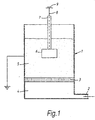
- the fluidisation and coating apparatus comprises an earthed (connected to the earth terminal of the mains supply) vessel (1) having an air inlet (2) at its base and a porous air distribution membrane (3) disposed transversely so as to divide the vessel into a lower plenum (4) and an upper fluidising compartment (5).
- a workpiece (6) having an insulated support (7), preferably a rigid support, is immersed into a fluidised bed of a powder coating composition established in the fluidising compartment (5) by means of an upwardly-flowing stream of air introduced from the plenum (4) through the porous membrane (3).
- a direct voltage is applied to the workpiece (6) by means of a supply cable (8) from a variable voltage source (9).
- the workpiece becomes electrically charged and particles of the powder coating composition adhere thereto. There are no ionisation or corona effects and, for that reason, the workpiece is substantially isolated electrically, a consequence of which is that the amperage is very low.
- the workpiece may be moved in a regular oscillatory manner during the coating process by means not shown in Fig. 1. Instead, the workpiece may be advanced through the bed either intermittently or continuously during immersion, or may be repeatedly immersed and withdrawn until the desired total period of immersion has been achieved.
- the workpiece After the desired period of immersion the workpiece is withdrawn from the fluidised bed, the applied voltage is disconnected and the workpiece is heated so as to melt and fuse the adhering particles of the powder coating composition and complete the coating.
- the workpiece comprises an )aluminium panel folded as shown to give a piece which is generally U-shaped in plan view (so as co define a central recess) and has dimensions as follows:
- the workpiece (6) was connected to the direct-current supply cable (8) by means of a crocodile clip (10) - Fig. 2 - mounted on an insulating support (7) in the form of a rod of length 300 mm.
- the workpiece was positioned centrally within the fluidising unit, giving rise to a minimum spacing of about 3.8 cm between the workpiece and the wall of the fluidising unit and resulting in a maximum potential gradient of about 0.79 kV/cm between the workpiece and the fluidising unit, when a voltage of 3 kV is applied to the workpiece. That is, satisfactory results are obtained for a maximum potential gradient that is expected to be no more than 1 kV/cm.
- the workpiece would need to be at a minimum distance of 0.1 cm from the wall of the fluidising unit in order for the maximum potential gradient to be 30 kV/cm when a voltage of 3 kV (the maximum used) is applied to the workpiece.
- the maximum potential gradient at 0.5 kV, the lowest voltage used is about 0.13 kv/cm and, as for some of the examples below, the lowest voltage may be 0.2 kV giving a maximum potential gradient of about 0.05 kv/cm.
- the fluidising air pressure was 1 bar in each case.
- the standard bake and cure of the deposited material in each Example comprised heating at 200°C for 5 minutes.
- the particle size data reported in the Examples was determined using the Mastersizer X laser light-scattering device manufactured by Malvern Instruments.
- d(v)X volume percentiles d(v)X, where X is the percentage of the total volume of the particles that lies below the stated particle size d.
- d(v) 50 is the median particle size of the sample.
- the powder coating composition used in this Example was a white epoxy polyester hybrid powder designed for corona application and formulated as follows: Parts by weight Rutile Titanium Dioxide 321 Filler (dolomite) 107 Carboxylic Acid-Functional Polyester Resin 374 Epoxy Resin Curing Agent 152 Catalyst 30 Wax 3 Flow Modifier 10 Benzoin 3 1000
- the ingredients were dry mixed in a blender, and fed into a twin-screw extruder operating at a temperature of 108°C.
- the extrudate was ground in an impact mill to produce a powder with the following particle size distribution: d(v) 99 106.11 microns d(v) 50 41.45 microns 6.31% ⁇ 10 microns 2.04% ⁇ 5 microns
- composition was blended with a 0.1% by weight addition of a synthetic silica flatting (matting) agent (fumed silica TS 100 ex-Degussa).
- the blended composition Before immersion of the workpiece, the blended composition was allowed to fluidise for 30 minutes in order to reach an equilibrium state.
- the workpiece was connected to the voltage source and then immersed in the equilibrated fluidised bed for a given "dip" time before being withdrawn from the bed. While immersed, the workpiece was slowly moved back and forth in a regular oscillatory manner. The process was repeated at different applied voltages and dip times.
- Table 1 summarises the characteristics of the finished coating after standard bake and cure, for various applied voltages and dip times. Voltage (Volts) Dip Time(s) % Coverage on 5mm Recessed Panel Film Tickness ( ⁇ m) Standard Deviation of Film Thickness ( ⁇ m) Outer Inner Max. Min. Mean 0 120 25 50 225 0 54 86 500 180 60 60 260 0 120 93 1000 180 75 20 387 6 194 104 1300 240 100 70 270 102 204 50 2000 60 90 45 288 8 198 84 2500 30 65 15 299 0 197 131 3000 30 45 20 400 0 211 163
- the U-shaped (recessed) panel (6) was first flattened out as far as practicable into generally rectangular form as shown in Fig. 3.
- the central portion (11) retained some recessed character because of the difficulty of achieving an uninterrupted planar form without damaging the applied coating during the unfolding procedure.
- the figure given in the Table for maximum film thickness in each experiment is the highest of the 36 readings, and the figure given for minimum film thickness is the lowest of the readings.
- the quoted mean figure is the arithmetic mean of the 36 readings and the standard deviation is derived for each experiment from the 36 readings obtained as described.
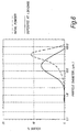
- Fig. 6 shows the particle size distribution of the material deposited on the workpiece in Example 1, as a function of deposition voltage and dip time, as compared with the particle size distribution of the initial powder coating composition. It will be seen that the finer particles are deposited preferentially, leading to progressive depletion of those particle sizes in the fluidised bed.
- the powder coating composition used in this Example was a white hybrid powder designed for tribostatic application, and formulated as follows: Parts by weight Rutile Titanium Dioxide 252 Filler (Calcium Carbonate) 140 Carboxylic Acid-Functional Polyester Resin (Uralac P5261 ex.DSM) 360 Epoxy Resin 230 Flow Modifier 10 Wax 5 Benzoin 3 1000
- the ingredients were dry mixed in a blender, and fed into a twin-screw extruder operating at a temperature of 108°C.
- the extrudate was ground in an impact mill to produce a powder with the following particle distribution: d(v) 99 118.84 microns d(v) 50 45.48 microns 6.06% ⁇ 10 microns 1.70% ⁇ 5 microns
- composition was blended with a 0.1% addition of aluminium oxide.
- the coating process was carried out as described in Example 1, except that the substrate was a planar, rectangular aluminium panel (100 mm x 60 mm) and a constant dip time of 100 seconds was used.
- Table 2 summarises the characteristics of the finished coating after standard bake and cure as a function of the applied deposition voltage. Voltage (Volts) Dip Time(s) % Coverage on (100x60)mm Flat Panel Film Thickness ( ⁇ m) Standard Deviation of Film Tnickness ( ⁇ m) Max. Min. Mean 0 150 25 62 0 41 12 500 150 60 109 0 73 26 750 150 95 109 21 61 24 1000 150 100 155 30 84 40 1500 150 100 225 75 130 47
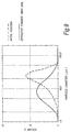
- Fig. 7.1 shows the particle size distribution of the material deposited on the workpiece in Example 2 as a function of the deposition voltage at constant dip time (150 seconds).
- the finer particles are deposited preferentially, with the maximum deposition being of particles of around 20 microns in diameter, and it will be seen that the deposited distribution curve is not much affected by changes in the deposition voltage.
- Fig. 7.2 shows the particle size distribution of the material deposited on the workpiece with a dip time of 60 seconds, as compared with the particle size distribution of the initial powder coating composition.
- the powder coating composition used in this Example was a brown polyester/TGIC powder designed for corona application and formulated as follows: Parts by weight Rutile Titanium Dioxide 6 Red Iron Oxide 27 Yellow Lead Chromate 35 Lamp Black 101 Fluffy 12 Filler (Barium Sulphate) 207 Carboxylic Acid-Functional Polyester Resin 650 TGIC 48 Flow Modifier 10 Wax 2 Benzoin 3 991
- the ingredients were dry mixed in a blender and fed into a twin-screw extruder operating at a temperature of 130°C.
- the extrudate was ground in an impact mill to produce a powder with the following particle size distribution: d(v) 99 101.94 microns d(v) 50 37.62 microns 10.51% ⁇ 10 microns 3.98% ⁇ 5 microns
- composition was blended with a 0.1% by weight addition of a silica flatting (matting) agent.
- the coating process was carried out as described in Example 1, with a workpiece as shown in Fig. 2, except that a constant dip time of 240 seconds was used, and the applied voltage was negative rather than positive.
- Table 3 summarises the characteristics of the finished coating after standard bake and cure as a function of the applied deposition voltage: Voltage (Volts) -VE Time(s) % Coverage on Recessed Panel Film Thickness ( ⁇ m) Standard Deviation of Film Thickness ( ⁇ m) Outer Inner Max. Min. Mean 500 240 0 0 0 0 0 1000 240 75 55 37 0 23 13 1500 240 100 80 65 0 44 15 2000 240 100 100 100 55 69 11
- Fig. 8 shows the particle size distribution of the material deposited on the workpiece in Example 3 at a deposition voltage of -2 kV.
- the particle size distribution of the deposited material may be summarised as follows: d(v) 99 63.43 microns d(v) 50 15.13 microns 32.10% ⁇ 10 microns 12.42% ⁇ 5 microns
- the powder coating composition used in this Example was a white epoxy/polyester hybrid formulated as follows: Parts by weight Rutile Titanium Dioxide 352 Carboxylic Acid-Functional Polyester Resin 317 Epoxy Resin 314 Flow Modifier 10 Catalyst 1 Benzoin 3 Wax 3 996
- the ingredients were dry mixed in a blender and fed into a twin-screw extruder operating at a temperature of 108°C.
- the extrudate was ground in an impact mill to produce a powder with the following particle size distribution: d(v) 99 59.74 microns d(v) 50 21.61 microns 16.58% ⁇ 10 microns 5.19% ⁇ 5 microns
- composition was blended with 0.75% by weight of a dry flow additive comprising alumina and aluminium hydroxide (45% : 55% by weight).
- Table 4 summarises the characteristics of the finished coating after standard bake and cure as a function of the applied deposition voltage. Voltage (Volts) Time (s) % Coverage on 5mm recessed panel Film Thickness ( ⁇ m) Standard Deviation of Film Thickness ( ⁇ m) Outer Inner Max. Min. Mean 0 150 50 90 23 0 10 4 200 150 60 90 24 0 11 4 400 150 95 95 27 0 15 5 600 150 98 99 36 0 25 6 800 150 100 98 47 0 35 7 1000 150 100 100 63 19 43 8
- Fig. 9 shows the particle size distribution of the material deposited on the workpiece in Example 4 at 1kV, as compared with the particle size distribution of the initial coating composition.
- the particle size distribution of the deposited material may be summarised as follows: d(v) 99 43.15 microns d(v) 50 8.08 microns 60.60% ⁇ 10 microns 26.99% ⁇ 5 microns
- the powder coating composition used in this Example was the same as that used in Example 4, except that the dry flow additive comprising alumina and aluminium hydroxide (45 : 55 w/w) was incorporated in an amount of 0.3% by weight instead of 0.75% by weight.
- the coating process was carried out as described in Example 1, with a workpiece as shown in Fig. 2, except that a constant voltage of 1kV was used and the fluidising air pressure was 2 bar.
- Fig. 10 shows the particle size distribution of the material deposited on the workpiece in Example 5 at 360 seconds, as compared with the particle size distribution of the initial coating composition.
- the particle size distribution of the deposited material may be summarised as follows: d(v) 99 37.44 microns d(v) 50 12.23 microns 38.65% ⁇ 10 microns 14.02% ⁇ 5 microns
- the powder coating composition used in this example was the same as that used in Example 4, except that the composition was blended with 0.3% by weight of aluminium oxide C instead of the aluminium oxide/aluminium hydroxide additive.
- the coating process was carried out as described in Example 1, with a workpiece as shown in Fig. 2, except that the fluidising air pressure was 2 bar.
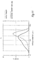
- Fig. 11 shows the particle size distribution of the material deposited on the workpiece in Example 6 at 360 seconds, as compared with the particle size distribution of the initial coating composition.
- the particle size distribution of the deposited material may be summarised as follows: d(v) 99 38.94 microns d(v) 50 11.65 microns 43.05% ⁇ 10 microns 18.52% ⁇ 5 microns
- the powder coating composition used in this Example was the same as that used in Example 4, except that the composition was blended with 0.3% by weight of silica instead of the aluminium oxide/aluminium hydroxide additive.
- the coating process was carried out as described in Example 1, with a workpiece as shown in Fig. 2, except that negative voltages were applied to the workpiece and the fluidising air pressure was 2 bar.
- Fig. 12 shows the particle size distribution of the material deposited on the workpiece in Example 7 at -1.5 kV and 150 seconds, as compared with the particle size distribution of the initial coating composition.
- the particle size distribution of the deposited material may be summarised as follows: d(v) 99 37.64 microns d(v) 50 9.13 microns 55.62% ⁇ 10 microns 17.58% ⁇ 5 microns
- the powder coating composition used in this Example was a grey epoxy/dicyandiamide powder formulated as 15 follows: Parts by weight Rutile Titanium Dioxide 204 Heucosin Fast Blue 5 Lamp Black 101 Fluffy 2 Filler (Dolomite) 63 Filler (Barium Sulphate) 84 Epoxy Resin 600 Epicure P-104 (ex.Shell Chemicals) 8 Benzoin 3 1000
- the ingredients were dry mixed in a blender, and fed into a twin-screw extruder operating at a temperature of 90°C.
- the extrudate was ground in an impact mill to produce a powder with the following particle size distribution: d(v) 99 68.57 microns d(v) 50 22.67 microns 14.68% ⁇ 10 microns 5.23% ⁇ 5 microns
- composition was blended with 0.75% by weight of an additive comprising aluminium oxide and aluminium hydroxide (45 : 55 w/w).
- Example 2 The coating process was carried out as described in Example 1, with a workpiece as shown in Fig. 2, but with negative applied voltages and varying the fluidising air pressure.
- the particle size distribution of the deposited material may be summarised as follows: d(v) 99 44.65 microns d(v) 50 10.66 microns 45.96% ⁇ 10 microns 13.08% ⁇ 5 microns
- the powder coating composition used in this Example was a green polyester/primid powder formulated as follows: Parts by weight Yellow Iron Oxide 16 Lamp Black 101 Fluffy 1 Monastral Green 19 Rutile Titanium Dioxide 7 Carboxylic Acid-Functional Polyester Resin 570 Primid XL552 (ex. EMS) 30 Filler 341 Benzoin 3 Flow Modifier 10 Wax 3 993
- the ingredients were dry mixed in a blender and fed into a twin-screw extruder operating at a temperature of 130°C.
- the extrudate was ground in an impact mill to produce a powder with the following particle size distribution: d(v) 99 78.7 microns d(v) 50 26.26 microns 12.77% ⁇ 10 microns 5.21% ⁇ 5 microns
- composition was blended with 0.3% by weight of an additive comprising aluminium oxide and aluminium hydroxide (45 : 55 w/w).
- the coating process was carried out as described in Example 1, except that the substrate was a planar, rectangular aluminium panel (100 mm x 50 mm), a constant dip time of 150 seconds was used, and the applied voltage was varied from + 1kV to - 1kV.
- the particle size distribution of the deposited material may be summarised as follows: d(v) 99 44.34 microns d(v) 50 16.61 microns 21.85% ⁇ 10 microns 7.91% ⁇ 5 microns
- the powder coating composition used in this Example was a white hybrid powder formulated as follows: Parts by weight Rutile Titanium Dioxide 398 Carboxylic Acid-Functional Polyester Resin 343 Epoxy Resin 233 Flow Modifier 10 Benzoin 3 Wax 3 990
- the ingredients were dry mixed in a blender and fed into a twin-screw extruder at a temperature of 108°C.
- the extrudate was ground in an impact mill to produce a powder with the following particle size distribution: d(v) 99 89.56 microns d(v) 50 32.58 microns 7.95% ⁇ 10 microns 2.56% ⁇ 5 microns
- composition was blended with 0.75% by weight of an additive comprising aluminium oxide and aluminium hydroxide (45 : 55 w/w).
- the coating process was carried out as described in Example 1, except that the substrate was a planar, rectangular steel panel (150 mm x 100 mm) pre-treated with zinc phosphate, a constant dip time of 150 seconds was used, and negative voltages were applied to the substrate.
- the particle size distribution of the deposited material may be summarised as follows: d(v) 99 51.81 microns d(v) 50 13.40 microns 33.97% ⁇ 10 microns 10.63% ⁇ 5 microns
- the maximum potential gradient in the fluidising gas is likely to be about 0.79 kV/cm and, for the voltage range of 0.2 kV to 3 kV used in the above Examples, the maximum potential gradient present in any of the Examples is expected to be within the range 0.05 kV/cm to 10 kV/cm.
- the powder coating composition used in this Example was the same as that used in Example 10.
- the substrate was an aluminium extrusion as shown in Figs. 4 and 5.
- the dimensions of the faces designated d to g in Fig. 4 are as follows:
- the substrate would fit into a rectangular "tube" of height 7.5 cm, width 4.5 cm and depth 3.9 cm.
- the minimum spacing between the substrate and the wall of the fluidisation unit would be about 4.4 cm, resulting in a maximum potential gradient between the substrate and the fluidisation unit of about 0.23 kV/cm when the voltage applied to the substrate is 1 kv.
- Air serves as the fluidising gas and a maximum potential gradient of 0.23 kV/cm is well below the ionisation potential gradient of 30 kV/cm for air at atmospheric pressure.
- the maximum potential gradient present in the apparatus used in the experiment is expected to lie below 1 kV/cm.
- the voltage applied to the substrate is 1 kV
- the substrate would need to come within 0.033 cm of the wall of the fluidisation unit for the maximum potential gradient to reach 30 kV/cm. Allowing for oscillation or vibration of the workpiece, it is expected that the conditions would result in maximum potential gradients in the range 0.05 kV/cm to 10 kV/cm, as stated above.
- the coating process was carried out as described in Example 1 with a dip time of 150 seconds at 1kV.
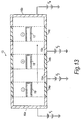
- a fluidised-bed of a powder coating composition is established within the fluidisation chamber (13) and a series of workpieces (17,18,19) is immersed and transported through the bed in a direction shown (by means not shown).
- Each workpiece shown in Fig. 13 is of the form shown in Fig. 2, but the apparatus can in principle be used to coat articles of any desired shape.
- the workpieces are electrically charged by means of direct voltages in such a way that the polarities of successive workpieces are in alternating sequence.
- the alternating polarities of the workpieces and the voltages applied to the conducting sections 15a, 15b, 16a and 16b of the wall of the fluidising chamber 13, along with the bipolar charging of the powder particles, result in the workpieces being subjected to a sequence of conditions as they pass through the fluidising chamber.
- the conducting sections 15a, 15b, 16a and 16b may, alternatively, be all connected to the earth terminal of the mains supply rather than to voltage sources.
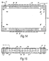
- an arrangement 20 used in carrying out Example 12, described below includes side (as viewed) pillars 21 of electrically insulating material, upper and lower (as viewed) steel bars 22 and 23, a corrugated steel panel 24, a steel front (as viewed) plate 25, a steel rear (as viewed) plate 26, a plurality of securing bolts 27 holding the steel plates 25 and 26 firmly together with the corrugated steel panel 24 between the steel plates 25 and 26, a first plurality of steel rods 28 passing through front (as viewed) recesses of the corrugated steel panel 24 in addition to passing through apertures in the steel bars 22 and 23 and a second plurality of steel rods 29 passing through rear (as viewed) recesses of the corrugated steel panel 24 in addition to passing through apertures in the steel bars 22 and 23.
- the ends of the steel rods 28 and 29 are threaded and nuts screwed along the threaded ends of the steel rods 28 and 29 securing them to the upper and lower steel bars 22 and 23.
- the side pillars 21 are attached to the upper and lower steel bars 22 and 23, forming a rigid frame.
- the side pillars 21 are also securely clamped between the front and rear steel plates 25 and 26 by threaded bolts secured by nuts.
- the arrangement 20 is a rigid assembly in which the front plate 25, the rear plate 26 and the corrugated panel 24 form a first conductive sub-assembly while the upper bar 22, the lower bar 23 and the rods 28, 29 form a second sub-assembly.
- the first and second sub-assemblies are isolated electrically from each other by the nonconductive pillars 21 and no parts of the two sub-assemblies contact one another.
- the corrugated panel 24 includes corrugations of a maximum depth of 4 cm and the dimensions of the panel 24 are 30 cm (length) by 18 cm (height).
- the corrugated panel 24 serves as the workpiece and the rods 28, 29 serve as counter-electrodes in Example 12 described below.
- the arrangement 20 is 4 cm thick and its overall dimensions are 42 cm (length) by 24 cm (height).
- the front and rear plates 22 and 23 are each 18 cm high.
- the powder coating composition used in this Example was a white epoxy/polyester hybrid formulated as in Example 4.
- the ingredients were dry mixed in a blender and fed into a twin screw extruder operating at a temperature of 108 C.
- the powder was blended with 0.6& by weight of a dry flow additive comprising alumina and aluminium hydroxide (45%:55% by weight).
- a rectangular fluidising vessel of dimensions 80 cm (length) by 40 cm (width) by 50 cm (height) was filled to three-quarters of its height with the powder described above and the powder was fluidised using compressed air at a pressure of 4 bar.
- the panel 24 and the front and rear plates 25, 26 were connected to a positive voltage of 2 kV.
- the upper bar 22 was connected to the earth terminal of the mains supply, maintaining the upper bar 22, the lower bar 23 and the rods 28, 29 at earth relative to the panel 24 and the plates 25, 26.
- the minimum distance between the rods 28, 29 and the panel was measured as 3 mm, giving a maximum potential gradient of 6.67 kV/cm between the charged and the earthed parts, well below the level of 30 kV/cm that would result in corona effect or ionisation in the fluidised bed.
- the maximum potential gradient of 6.67 kV/cm lies within the range 0.05 kv/cm to 10 kV/cm given above.
- the arrangement 20 including the workpiece 24 and the counter-electrodes 28, 29 was immersed vertically in the fluidised-bed for a time of 300 seconds during which the arrangement 20 was subjected to front-to-back oscillatory motion and, also, a vertical dipping motion, maintaining powder fluidity in the recesses of the workpiece 24.
- the process was carried out three times with different numbers of rods 28, 29 as described in the following three experiments.
- the workpiece 24 was removed and subjected to a standard bake and cure. The remaining apparatus was thoroughly cleaned of deposited powder and reassembled along with a replacement workpiece 24.
- the second plurality of rods 29 were included without the first plurality of rods 28. At the end of the coating period, there was found-to be 100% coverage of the rear recesses (as viewed) in the workpiece 24 facing the second plurality of rods 29. In the front recesses (as viewed) where the first plurality of rods 28 had been omitted, the workpiece 24 was found to be coated only to a depth of 4 cm below the upper edge and above the lower edge, the coating ending abruptly. The remainder of the front (as viewed) of the workpiece 24 was bare except for some specks of powder indicating virtually no powder deposition.
- Both the first and the second plurality of rods 28, 29 were included providing a rod in every recess in the workpiece 24. Full coating was achieved in both the front and rear recesses, the only bare areas being those which were in contact with the front and rear plates 25, 26.
- the perceived advantage of the process described above is that the presence of the earthed counter-electrodes in the recesses so influences the electric field around the workpiece as to cause the electric field to extend fully into the recesses whereas, without the earthed counter-electrodes, the electric field penetrates only slightly into the recesses.
- the improved penetration of the electric field into the recesses leads to improved penetration of the powder.
- the full penetration into narrow recessed parts is important to prevent corrosion in narrow recesses parts and is difficult or even impossible to achieve with conventional coating processes.
- an arrangement 30 used in carrying out Example 13, described below includes a bar 31 carrying holders 33, 34 for a workpiece and counter-electrodes, respectively, and guides 32 for mounting the bar 31 on a fluidising chamber (not shown.
- the arrangement 30 of Fig. 16 is shown mounted on a fluidising chamber 38 provided with an air input port 37.
- the arrangement 30 of Fig. 16 is shown as carrying a plate-like workpiece 36 and flanked by plate-like counter-electrodes 35.
- the powder coating composition used in this Example was a white epoxy/polyester hybrid formulated as in Example 4.
- the ingredients were dry mixed in a blender and fed into a twin screw extruder operating at a temperature of 108 °C.
- composition was blended with 0.25%, by weight, of a dry flow additive comprising alumina and aluminium hydroxide (45%:55% by weight).
- the rectangular fluid bed 38 of dimensions 80 cm (length) by 40 cm (width) by 50 cm (height) was filled to three-quarter height with the above powder and fluidised at a pressure of 4 bar.
- a planar, rectangular aluminium panel of dimensions 15 cm by 10 cm, serving as the workpiece 36, was charged positively and immersed in the fluidised-bed for up to 150 seconds, the workpiece 36 being positioned between two negatively charged plates serving as counter-electrodes 35.
- the charged workpiece 36 was given a side-to-side motion for the duration of its immersion.
- the perceived advantage of this process is the enhancement of the electric field between the workpiece 36 and the counter-electrodes 35 at the expense of the field between the workpiece 36 and the earthed walls of fluidising chamber 38.
- the reduction in the field between the workpiece 36 and the walls of the fluidising chamber 38 results in a reduction in the undesirable accumulation of powder on the walls of the fluidising chamber 38.
- Table 11 summarises the characteristics of the finished coating after a standard bake and cure as a function of the voltages applied to the workpiece 36 and the counter-electrodes 35, demonstrating the influence of the counter-electrodes.
Landscapes
- Chemical & Material Sciences (AREA)
- Organic Chemistry (AREA)
- Engineering & Computer Science (AREA)
- Materials Engineering (AREA)
- Mechanical Engineering (AREA)
- Metallurgy (AREA)
- Chemical Kinetics & Catalysis (AREA)
- Application Of Or Painting With Fluid Materials (AREA)
- Fertilizers (AREA)
- Paints Or Removers (AREA)
- Electrostatic Spraying Apparatus (AREA)
- Medicinal Preparation (AREA)
- Materials For Medical Uses (AREA)
- Coating Apparatus (AREA)
Claims (41)
- Procédé pour former un revêtement sur un substrat conducteur (6), qui consiste à établir un lit fluidisé d'une composition de revêtement en poudre, effectuant ainsi un chargement tribostatique de la composition de revêtement en poudre, à immerger le substrat (6) en tout ou partie à l'intérieur dudit lit fluidisé, à appliquer une tension au substrat pendant au moins une partie de la durée d'immersion, ainsi les particules chargées de la composition de revêtement en poudre adhèrent au substrat (6), à retirer le substrat (6) du lit fluidisé et à former les particules adhérentes en un revêtement continu sur au moins une partie du substrat (6).
- Procédé selon la revendication 1, dans lequel le substrat (6) comprend un métal.
- Procédé selon la revendication 1 ou 2, dans lequel la tension appliquée est une tension de courant continu.
- Procédé selon l'une quelconque des revendications 1 à 3, pour revêtir des substrats successifs (17, 18, 19) en séquence, dans lequel une tension de courant continu est utilisée et la polarité de la tension appliquée aux substrats successifs (17, 18, 19) est inversée de chaque substrat au suivant de façon à produire une séquence alternante.
- Procédé selon la revendication 4, qui est un procédé en continu dans lequel une série de substrats (17, 18, 19) de polarités alternées est transportée à travers un lit fluidisé établi à l'intérieur d'une chambre de fluidisation ayant des parois composées alternativement, dans la direction de déplacement des substrats (17, 18, 19), de sections isolantes (14a, 14b, 14c) et de sections conductrices (15a, 15b).
- Procédé selon l'une quelconque des revendications 1 à 3, qui comprend le revêtement en discontinu simultané d'une ou plusieurs paires de substrats disposés à l'intérieur d'un lit fluidisé commun, les substrats de chaque paire étant chargés par des tensions à courant continu aux polarités respectivement opposées.
- Procédé selon l'une quelconque des revendications 1 à 6, dans lequel le lit fluidisé est établi à l'intérieur d'un récipient mis à la terre (1).
- Procédé selon l'une quelconque des revendications 1 à 7, dans lequel une ou plusieurs contre-électrodes (35), de préférence mises à la terre, sont disposées dans la masse de la composition de revêtement en poudre.
- Procédé selon l'une quelconque des revendications 1 à 8, dans lequel il n'existe aucune connexion à la terre vers le substrat (6).
- Procédé selon l'une quelconque des revendications 1 à 9, dans lequel le substrat (6) est entièrement immergé dans le lit fluidisé.
- Procédé selon l'une quelconque des revendications 1 à 10, dans lequel il n'existe aucun préchauffage du substrat (6) avant l'immersion dans le lit fluidisé.
- Procédé selon l'une quelconque des revendications 1 à 11, dans lequel la composition de revêtement en poudre est un système thermodurcissable.
- Procédé selon l'une quelconque des revendications 1 à 12, dans lequel la composition de revêtement en poudre incorpore, par mélange à sec, un ou plusieurs additifs auxiliaires de fluidité.
- Procédé selon la revendication 13, dans lequel la composition de revêtement en poudre incorpore une combinaison d'alumine et d'hydroxyde d'aluminium en tant qu'additif auxiliaire de fluidité.
- Procédé pour revêtir un substrat conducteur (6) qui comprend un composant automobile ou aérospatial, dans lequel un premier revêtement dérivé d'une composition de revêtement en poudre est appliqué à l'aide d'un procédé selon l'une quelconque des revendications 1 à 14, puis une couche de finition est appliquée sur le revêtement en poudre.
- Appareil pour une utilisation dans un procédé selon l'une quelconque des revendications 1 à 15 pour former un revêtement sur un substrat conducteur, qui comprend :(a) une chambre de fluidisation ;(b) un moyen pour effectuer la fluidisation d'une composition de revêtement en poudre en vrac à l'intérieur de la chambre de fluidisation de façon à établir un lit fluidisé de la composition à l'intérieur, effectuant ainsi le chargement tribostatique de la composition de revêtement en poudre ;(c) un moyen pour immerger un substrat en tout ou partie à l'intérieur du lit fluidisé ;(d) un moyen pour appliquer une tension aux substrats pendant au moins une partie de la durée d'immersion, ainsi le substrat devient électriquement chargé de sorte que des particules chargées de la composition de revêtement en poudre y adhèrent;(e) un moyen pour retirer le substrat portant des particules adhérentes provenant du lit fluidisé ; et(f) un moyen pour convertir les particules adhérentes dans un revêtement en continu.
- Substrat (6) à chaque fois revêtu par un procédé selon l'une quelconque des revendications 1 à 15, ou à l'aide d'un appareil selon la revendication 16.
- Procédé selon l'une quelconque des revendications 1 à 15, dans lequel la tension appliquée au substrat (6) est telle que le gradient maximum de potentiel existant dans le lit fluidisé se situe sensiblement au-dessous du gradient de potentiel d'ionisation pour le gaz dans le lit fluidisé.
- Procédé selon l'une quelconque des revendications 1 à 15 ou 18, dans lequel le gradient maximum de potentiel existant dans le lit fluidisé se situe entre 0,05 kV/cm et 10 kV/cm, les deux limites étant incluses.
- Procédé selon la revendication 19, dans lequel le gradient maximum de potentiel existant dans le lit fluidisé se situe entre 0,05 kV/cm et 5 kV/cm, les deux limites étant incluses.
- Procédé selon la revendication 20, dans lequel le gradient maximum de potentiel existant dans le lit fluidisé se situe entre 0,05 kV/cm et 1 kV/cm, les deux limites étant incluses.
- Procédé selon l'une quelconque des revendications 1 à 15 ou 18 à 21, dans lequel la tension appliquée au substrat (6) se situe entre 5 kV/cm et 60 kV/cm, les deux limites étant incluses.
- Procédé selon la revendication 22, dans lequel la tension appliquée au substrat (6) se situe entre 1,5 kV/cm et 35 kV/cm, les deux limites étant incluses.
- Procédé selon la revendication 22, dans lequel la tension appliquée au substrat (6) se situe entre 5 kV/cm et 30 kV/cm, les deux limites étant incluses.
- Procédé selon la revendication 22, dans lequel la tension appliquée au substrat (6) se situe entre 30 kV/cm et 60 kV/cm, les deux limites étant incluses.
- Procédé selon l'une quelconque des revendications 1 à 15 ou 18 à 25, dans lequel la granulométrie des particules de la composition de revêtement en poudre varie entre 1 et 120 micromètres, les deux limites étant incluses.
- Procédé selon la revendication 26, dans lequel la granulométrie des particules varie entre 15 et 75 µm, les deux limites étant incluses.
- Procédé selon la revendication 27, dans lequel la granulométrie des particules varie entre 25 et 50 µm, les deux limites étant incluses.
- Procédé selon la revendication 27, dans lequel la granulométrie des particules varie entre 20 et 45 µm, les deux limites étant incluses.
- Procédé selon l'une quelconque des revendications 1 à 15 ou 18 à 29, dans lequel le substrat (6) reçoit un revêtement d'une épaisseur comprise entre 5 et 200 µm, les deux limites étant incluses.
- Procédé selon la revendication 30, dans lequel le substrat (6) reçoit un revêtement d'une épaisseur comprise entre 5 et 100 µm, les deux limites étant incluses.
- Procédé selon la revendication 30, dans lequel le substrat (6) reçoit un revêtement d'une épaisseur comprise entre 10 et 150 µm, les deux limites étant incluses.
- Procédé selon la revendication 32, dans lequel le substrat (6) reçoit un revêtement d'une épaisseur comprise entre 20 et 100 µm, les deux limites étant incluses.
- Procédé selon la revendication 33, dans lequel le substrat (6) reçoit un revêtement d'une épaisseur comprise entre 60 et 80 µm, les deux limites étant incluses.
- Procédé selon la revendication 33, dans lequel le substrat (6) reçoit un revêtement d'une épaisseur comprise entre 80 et 100 µm, les deux limites étant incluses.
- Procédé selon la revendication 31, dans lequel le substrat (6) reçoit un revêtement d'une épaisseur comprise entre 50 et 150 µm, les deux limites étant incluses.
- Procédé selon la revendication 32, dans lequel le substrat (6) reçoit un revêtement d'une épaisseur comprise entre 15 et 40 µm, les deux limites étant incluses.
- Procédé selon l'une quelconque des revendications 1 à 15 ou 18 à 37, dans lequel moins de 10 mA circule dans le substrat (6).
- Procédé selon la revendication 38, dans lequel moins de 5 mA circule dans le substrat (6).
- Procédé selon la revendication 39, dans lequel moins de 1 mA circule dans le substrat (6).
- Substrat (6) à chaque fois revêtu par un procédé selon l'une quelconque des revendications 18 à 40 ou à l'aide d'un appareil selon la revendication 16.
Applications Claiming Priority (5)
| Application Number | Priority Date | Filing Date | Title |
|---|---|---|---|
| GBGB9726645.6A GB9726645D0 (en) | 1997-12-17 | 1997-12-17 | Powder coating process |
| GB9726645 | 1997-12-17 | ||
| GBGB9821195.6A GB9821195D0 (en) | 1997-12-17 | 1998-09-30 | Powder coating process |
| GB9821195 | 1998-09-30 | ||
| PCT/GB1998/003777 WO1999030838A1 (fr) | 1997-12-17 | 1998-12-16 | Procede d'application de revetement en poudre |
Publications (2)
| Publication Number | Publication Date |
|---|---|
| EP1042075A1 EP1042075A1 (fr) | 2000-10-11 |
| EP1042075B1 true EP1042075B1 (fr) | 2002-09-11 |
Family
ID=26312788
Family Applications (1)
| Application Number | Title | Priority Date | Filing Date |
|---|---|---|---|
| EP98960033A Expired - Lifetime EP1042075B1 (fr) | 1997-12-17 | 1998-12-16 | Procede d'application de revetement en poudre |
Country Status (23)
| Country | Link |
|---|---|
| US (1) | US6280798B1 (fr) |
| EP (1) | EP1042075B1 (fr) |
| JP (1) | JP2002508247A (fr) |
| CN (1) | CN1207107C (fr) |
| AT (1) | ATE223763T1 (fr) |
| AU (1) | AU747317B2 (fr) |
| BR (1) | BR9813745A (fr) |
| CA (1) | CA2314075A1 (fr) |
| CZ (1) | CZ20002274A3 (fr) |
| DE (1) | DE69807934T2 (fr) |
| DK (1) | DK1042075T3 (fr) |
| ES (1) | ES2183429T3 (fr) |
| GB (1) | GB2347367B (fr) |
| HK (1) | HK1028367A1 (fr) |
| HU (1) | HU223153B1 (fr) |
| ID (1) | ID25506A (fr) |
| MX (1) | MXPA00005989A (fr) |
| NO (1) | NO20003123D0 (fr) |
| NZ (1) | NZ505036A (fr) |
| PL (1) | PL194993B1 (fr) |
| PT (1) | PT1042075E (fr) |
| TR (1) | TR200001744T2 (fr) |
| WO (1) | WO1999030838A1 (fr) |
Cited By (1)
| Publication number | Priority date | Publication date | Assignee | Title |
|---|---|---|---|---|
| DE102017106272A1 (de) | 2017-03-23 | 2018-09-27 | Dr. Schneider Kunststoffwerke Gmbh | Verfahren zum Aufbringen von Titanoxid auf ein Substrat |
Families Citing this family (55)
| Publication number | Priority date | Publication date | Assignee | Title |
|---|---|---|---|---|
| FR2795004A1 (fr) † | 1999-06-15 | 2000-12-22 | Atofina | Procede de recouvrement d'un objet par un film et appareillage pour la mise en oeuvre de ce procede |
| GB0113783D0 (en) * | 2001-06-06 | 2001-07-25 | Int Coatings Ltd | Powder coating process |
| GB2385810B (en) * | 2002-03-01 | 2005-03-09 | Spice Applic Systems Ltd | Product coating method and apparatus |
| US6948537B2 (en) | 2002-05-31 | 2005-09-27 | John Jones | Systems and methods for collecting a particulate substance |
| DE10233344A1 (de) * | 2002-07-23 | 2004-02-12 | Degussa Ag | Polyamid-Wirbelsinterpulver für das Dünnschichtwirbelsintern |
| GB0229003D0 (en) | 2002-12-12 | 2003-01-15 | Int Coatings Ltd | Powder coating process |
| GB0229004D0 (en) * | 2002-12-12 | 2003-01-15 | Int Coatings Ltd | Powder coating apparatus and process |
| EP1600524A4 (fr) * | 2003-02-10 | 2009-06-17 | Toshio Narita | Procede pour former un film resistant a la corrosion a haute temperature |
| CN1304125C (zh) * | 2003-05-24 | 2007-03-14 | 杭州五源科技实业有限公司 | 小型金属工件无触点粉末涂装的方法 |
| US20040265504A1 (en) * | 2003-06-27 | 2004-12-30 | Christophe Magnin | Non-metalic substrate having an electostatically applied activatable powder adhesive |
| GB2406806B (en) * | 2003-10-10 | 2006-11-15 | Spice Applic Systems Ltd | Product coating method and apparatus |
| US7501150B2 (en) * | 2004-01-28 | 2009-03-10 | Xerox Corporation | Emulsion aggregation process for forming powder coating compositions, powder coating compositions and method for using the same |
| US7985524B2 (en) * | 2004-01-28 | 2011-07-26 | Xerox Corporation | Emulsion aggregation process for forming curable powder coating compositions, curable powder coating compositions and method for using the same |
| DE102004046744B4 (de) * | 2004-09-27 | 2007-05-24 | Atotech Deutschland Gmbh | Verfahren zur Übertragung von Pulvern und Pulverlacken auf Substrate und Verwendung zur Herstellung von Leiterplatten und Solarzellen |
| FR2878453B1 (fr) * | 2004-11-30 | 2007-03-16 | Centre Nat Rech Scient Cnrse | Dispositif de fourniture de vapeurs d'un precurseur solide a un appareil de traitement |
| US20060286220A1 (en) * | 2005-06-01 | 2006-12-21 | Peter King | Product coating method and apparatus |
| ITMI20051303A1 (it) * | 2005-07-08 | 2007-01-09 | Inxel S R L | Metodo per la produzione di vernici in polvere termoindurenti particolarmente per l'applicazione mediante impianti elettrostatici |
| US20090017209A1 (en) * | 2005-07-11 | 2009-01-15 | Andrew Robert Morgan | Process for preparing a powder coating composition |
| DE602006010558D1 (de) * | 2005-07-11 | 2009-12-31 | Akzo Nobel Coatings Int Bv | Verfahren zur elektrostatischen pulverbeschichtung im wirbelbett |
| EP1952202A2 (fr) * | 2005-07-11 | 2008-08-06 | Akzo Nobel Coatings International BV | Poudres de toner et procédé pour leurs préparation |
| ATE419293T1 (de) * | 2005-07-11 | 2009-01-15 | Akzo Nobel Coatings Int Bv | Pulverbeschichtungsmaterialien |
| CA2618856C (fr) * | 2005-09-02 | 2014-05-06 | Span Tech Llc | Connecteur resistant a l'usure pour tapis transporteur articule modulaire |
| EP1759774A1 (fr) | 2005-09-05 | 2007-03-07 | Akzo Nobel Coatings International B.V. | Procédé de revêtement de pierres et pierres ainsi revêtues |
| JP2009532308A (ja) | 2006-04-03 | 2009-09-10 | スパン テック エルエルシー | 粉末コーティングを施した製品搬送用コンポーネント及びそれに関連する方法 |
| US7981465B2 (en) * | 2007-01-16 | 2011-07-19 | Globe Motors, Inc. | Method and apparatus for powder coating stator stacks |
| EP2271726A1 (fr) * | 2008-04-17 | 2011-01-12 | Dow Global Technologies Inc. | Agent de soutènement enrobé de poudre et son procédé de fabrication |
| FR2945824B3 (fr) * | 2009-05-20 | 2011-04-22 | Forges De Courcelles | Procede anti-corrosion de pieces obtenues par forgeage a chaud et installation de mise en oeuvre |
| CA3003338C (fr) | 2012-01-17 | 2020-09-15 | Automatic Coating Limited | Appareil de revetement |
| EP2757571B1 (fr) * | 2013-01-17 | 2017-09-20 | IMS Nanofabrication AG | Dispositif d'isolation haute tension pour appareil optique à particules chargées |
| JP2015023286A (ja) | 2013-07-17 | 2015-02-02 | アイエムエス ナノファブリケーション アーゲー | 複数のブランキングアレイを有するパターン画定装置 |
| EP2913838B1 (fr) | 2014-02-28 | 2018-09-19 | IMS Nanofabrication GmbH | Compensation de mini-faisceaux défectueux dans un outil d'exposition à faisceaux multiples de particules chargées |
| US9443699B2 (en) | 2014-04-25 | 2016-09-13 | Ims Nanofabrication Ag | Multi-beam tool for cutting patterns |
| EP2950325B1 (fr) | 2014-05-30 | 2018-11-28 | IMS Nanofabrication GmbH | Compensation de l'inhomogénéité de dose au moyen de points d'exposition se chevauchant |
| CN104028429A (zh) * | 2014-06-25 | 2014-09-10 | 梧州恒声电子科技有限公司 | 金属制品的静电粉末喷涂工艺 |
| JP6890373B2 (ja) | 2014-07-10 | 2021-06-18 | アイエムエス ナノファブリケーション ゲーエムベーハー | 畳み込みカーネルを使用する粒子ビーム描画機における結像偏向の補償 |
| US9568907B2 (en) | 2014-09-05 | 2017-02-14 | Ims Nanofabrication Ag | Correction of short-range dislocations in a multi-beam writer |
| US9653263B2 (en) | 2015-03-17 | 2017-05-16 | Ims Nanofabrication Ag | Multi-beam writing of pattern areas of relaxed critical dimension |
| EP3096342B1 (fr) | 2015-03-18 | 2017-09-20 | IMS Nanofabrication AG | Écriture multi-faisceaux à double passage bidirectionnel |
| US10410831B2 (en) | 2015-05-12 | 2019-09-10 | Ims Nanofabrication Gmbh | Multi-beam writing using inclined exposure stripes |
| EP3371346A4 (fr) * | 2015-11-05 | 2018-11-21 | Phosfan Ltd. | Revêtements composites au phosphate |
| US20190030562A1 (en) * | 2016-02-26 | 2019-01-31 | Beneq Oy | Improved coating process and apparatus |
| WO2017144782A1 (fr) * | 2016-02-26 | 2017-08-31 | Beneq Oy | Dispositif et procédé améliorés de revêtement aérosol |
| US10325756B2 (en) | 2016-06-13 | 2019-06-18 | Ims Nanofabrication Gmbh | Method for compensating pattern placement errors caused by variation of pattern exposure density in a multi-beam writer |
| US10325757B2 (en) | 2017-01-27 | 2019-06-18 | Ims Nanofabrication Gmbh | Advanced dose-level quantization of multibeam-writers |
| US10730068B2 (en) | 2017-08-15 | 2020-08-04 | Automatic Coating Limited | Coating apparatus |
| US10522329B2 (en) | 2017-08-25 | 2019-12-31 | Ims Nanofabrication Gmbh | Dose-related feature reshaping in an exposure pattern to be exposed in a multi beam writing apparatus |
| US11569064B2 (en) | 2017-09-18 | 2023-01-31 | Ims Nanofabrication Gmbh | Method for irradiating a target using restricted placement grids |
| US10651010B2 (en) | 2018-01-09 | 2020-05-12 | Ims Nanofabrication Gmbh | Non-linear dose- and blur-dependent edge placement correction |
| US10840054B2 (en) | 2018-01-30 | 2020-11-17 | Ims Nanofabrication Gmbh | Charged-particle source and method for cleaning a charged-particle source using back-sputtering |
| US11099482B2 (en) | 2019-05-03 | 2021-08-24 | Ims Nanofabrication Gmbh | Adapting the duration of exposure slots in multi-beam writers |
| DE102019118558A1 (de) * | 2019-07-09 | 2021-01-14 | Braun Sondermaschinen Gmbh | Verfahren und Vorrichtung zum Pulverbeschichten eines Objektes |
| KR20210132599A (ko) | 2020-04-24 | 2021-11-04 | 아이엠에스 나노패브릭케이션 게엠베하 | 대전 입자 소스 |
| CN113441375B (zh) * | 2021-06-25 | 2023-03-21 | 东风汽车集团股份有限公司 | 一种汽车车身的涂层结构及其制备方法 |
| CN114472002B (zh) * | 2021-09-22 | 2023-04-18 | 中大体育产业集团股份有限公司 | 一种包胶哑铃的增材粉喷装置 |
| CN114472103A (zh) * | 2022-01-25 | 2022-05-13 | 潍坊联威机械有限公司 | 一种用于管件内表面涂塑的连通器式流化床及其加工工艺 |
Family Cites Families (16)
| Publication number | Priority date | Publication date | Assignee | Title |
|---|---|---|---|---|
| BE573489A (fr) | 1957-12-03 | 1959-04-01 | Union Carbide Corp | Objet manufacturé recouvert d'une couche ou se composant de matières réfractaires pures. |
| FR83092A (fr) | 1962-06-22 | 1900-01-01 | ||
| FR1360556A (fr) * | 1962-06-22 | 1964-05-08 | British Ropes Ltd | Perfectionnements au revêtement d'objets |
| GB1059166A (en) * | 1962-09-10 | 1967-02-15 | Ivy Rose Anna Fair | Improvements in or relating to coating processes |
| US3502492A (en) * | 1965-12-13 | 1970-03-24 | Ransburg Electro Coating Corp | Metal substrate coated with epoxy powder primer and plasticized polyvinyl chloride topcoat and method of making same |
| US3670699A (en) * | 1970-06-24 | 1972-06-20 | Minnesota Mining & Mfg | Electrostatically charged fluidized bed apparatus |
| US3871328A (en) * | 1972-04-13 | 1975-03-18 | William P English | Coating chamber |
| US4009223A (en) | 1974-05-08 | 1977-02-22 | Westinghouse Electric Corporation | Thin film electrostatic epoxy coating powder |
| US4088093A (en) | 1976-04-13 | 1978-05-09 | Continental Can Company, Inc. | Web coating and powder feed |
| DD126791A1 (fr) * | 1976-07-27 | 1977-08-10 | ||
| US4188413A (en) * | 1976-10-18 | 1980-02-12 | General Electric Company | Electrostatic-fluidized bed coating of wire |
| JPS5775173A (en) | 1980-07-25 | 1982-05-11 | Fujimoto Masazo | Method for coating resin on metallic material |
| JPH0675692B2 (ja) | 1985-05-16 | 1994-09-28 | 小野田セメント株式会社 | 静電粉体塗装方法及塗装装置 |
| DD242353B5 (de) * | 1985-11-05 | 1996-09-19 | Atochem Elf Sa | Vorrichtung zum elektrostatischen Beschichten von Gegenstaenden in einem Tauchbecken |
| FR2720959B1 (fr) * | 1994-06-08 | 1999-03-26 | Atochem Elf Sa | Bain fluidisé électrostatique avec électrode semi-conductrice pour le revêtement de substrats avec des poudres, poudres utilisables et substrats revêtus de telles poudres. |
| DE19616695A1 (de) * | 1996-04-26 | 1997-11-06 | Dresler Peter Dr Ing | Verfahren und Vorrichtung zum elektrostatischen Beschichten von Gegenständen |
-
1998
- 1998-12-16 WO PCT/GB1998/003777 patent/WO1999030838A1/fr active IP Right Grant
- 1998-12-16 MX MXPA00005989A patent/MXPA00005989A/es not_active IP Right Cessation
- 1998-12-16 GB GB0014874A patent/GB2347367B/en not_active Expired - Fee Related
- 1998-12-16 BR BR9813745-0A patent/BR9813745A/pt not_active IP Right Cessation
- 1998-12-16 AU AU15718/99A patent/AU747317B2/en not_active Ceased
- 1998-12-16 PL PL341363A patent/PL194993B1/pl not_active IP Right Cessation
- 1998-12-16 CZ CZ20002274A patent/CZ20002274A3/cs unknown
- 1998-12-16 PT PT98960033T patent/PT1042075E/pt unknown
- 1998-12-16 CA CA002314075A patent/CA2314075A1/fr not_active Abandoned
- 1998-12-16 NZ NZ505036A patent/NZ505036A/en unknown
- 1998-12-16 US US09/555,884 patent/US6280798B1/en not_active Expired - Lifetime
- 1998-12-16 CN CNB98813666XA patent/CN1207107C/zh not_active Expired - Fee Related
- 1998-12-16 TR TR2000/01744T patent/TR200001744T2/xx unknown
- 1998-12-16 ES ES98960033T patent/ES2183429T3/es not_active Expired - Lifetime
- 1998-12-16 JP JP2000538806A patent/JP2002508247A/ja not_active Ceased
- 1998-12-16 AT AT98960033T patent/ATE223763T1/de not_active IP Right Cessation
- 1998-12-16 HU HU0100097A patent/HU223153B1/hu not_active IP Right Cessation
- 1998-12-16 DK DK98960033T patent/DK1042075T3/da active
- 1998-12-16 ID IDW20001084A patent/ID25506A/id unknown
- 1998-12-16 EP EP98960033A patent/EP1042075B1/fr not_active Expired - Lifetime
- 1998-12-16 DE DE69807934T patent/DE69807934T2/de not_active Expired - Lifetime
-
2000
- 2000-06-16 NO NO20003123A patent/NO20003123D0/no not_active Application Discontinuation
- 2000-12-06 HK HK00107826A patent/HK1028367A1/xx not_active IP Right Cessation
Cited By (1)
| Publication number | Priority date | Publication date | Assignee | Title |
|---|---|---|---|---|
| DE102017106272A1 (de) | 2017-03-23 | 2018-09-27 | Dr. Schneider Kunststoffwerke Gmbh | Verfahren zum Aufbringen von Titanoxid auf ein Substrat |
Also Published As
| Publication number | Publication date |
|---|---|
| DE69807934T2 (de) | 2003-05-28 |
| EP1042075A1 (fr) | 2000-10-11 |
| PL194993B1 (pl) | 2007-07-31 |
| HUP0100097A3 (en) | 2002-02-28 |
| GB2347367B (en) | 2002-01-09 |
| HK1028367A1 (en) | 2001-02-16 |
| HU223153B1 (hu) | 2004-03-29 |
| ATE223763T1 (de) | 2002-09-15 |
| NO20003123L (no) | 2000-06-16 |
| CN1284900A (zh) | 2001-02-21 |
| NO20003123D0 (no) | 2000-06-16 |
| CA2314075A1 (fr) | 1999-06-24 |
| GB2347367A (en) | 2000-09-06 |
| WO1999030838A1 (fr) | 1999-06-24 |
| TR200001744T2 (tr) | 2000-12-21 |
| US6280798B1 (en) | 2001-08-28 |
| JP2002508247A (ja) | 2002-03-19 |
| MXPA00005989A (es) | 2002-09-18 |
| NZ505036A (en) | 2001-12-21 |
| ES2183429T3 (es) | 2003-03-16 |
| DK1042075T3 (da) | 2003-01-06 |
| ID25506A (id) | 2000-10-05 |
| PT1042075E (pt) | 2003-01-31 |
| CN1207107C (zh) | 2005-06-22 |
| DE69807934D1 (de) | 2002-10-17 |
| PL341363A1 (en) | 2001-04-09 |
| AU747317B2 (en) | 2002-05-16 |
| BR9813745A (pt) | 2000-10-17 |
| CZ20002274A3 (cs) | 2001-12-12 |
| HUP0100097A2 (hu) | 2001-05-28 |
| GB0014874D0 (en) | 2000-08-09 |
| AU1571899A (en) | 1999-07-05 |
Similar Documents
| Publication | Publication Date | Title |
|---|---|---|
| EP1042075B1 (fr) | Procede d'application de revetement en poudre | |
| US7323226B2 (en) | Tribostatic fluidised bed powder coating process | |
| EP1392451B1 (fr) | Procede d'application de revetement en poudre a l'aide d'un lit fluidise charge electrostatiquement | |
| ZA200505563B (en) | Powder coating apparatus and process | |
| AU2002302843A1 (en) | Powder coating process with tribostatically charged fluidised bed | |
| KR100627502B1 (ko) | 분말 도장 방법 |
Legal Events
| Date | Code | Title | Description |
|---|---|---|---|
| PUAI | Public reference made under article 153(3) epc to a published international application that has entered the european phase |
Free format text: ORIGINAL CODE: 0009012 |
|
| 17P | Request for examination filed |
Effective date: 20000712 |
|
| AK | Designated contracting states |
Kind code of ref document: A1 Designated state(s): AT BE CH CY DE DK ES FI FR GB GR IE IT LI LU MC NL PT SE Kind code of ref document: A1 Designated state(s): AT BE CH CY DE DK ES FI FR GR IE IT LI LU MC NL PT SE |
|
| GRAG | Despatch of communication of intention to grant |
Free format text: ORIGINAL CODE: EPIDOS AGRA |
|
| 17Q | First examination report despatched |
Effective date: 20010119 |
|
| GRAG | Despatch of communication of intention to grant |
Free format text: ORIGINAL CODE: EPIDOS AGRA |
|
| GRAG | Despatch of communication of intention to grant |
Free format text: ORIGINAL CODE: EPIDOS AGRA |
|
| GRAH | Despatch of communication of intention to grant a patent |
Free format text: ORIGINAL CODE: EPIDOS IGRA |
|
| GRAH | Despatch of communication of intention to grant a patent |
Free format text: ORIGINAL CODE: EPIDOS IGRA |
|
| GRAA | (expected) grant |
Free format text: ORIGINAL CODE: 0009210 |
|
| RBV | Designated contracting states (corrected) |
Designated state(s): AT BE CH CY DE DK ES FI FR GR IE IT LI LU MC NL PT SE |
|
| AK | Designated contracting states |
Kind code of ref document: B1 Designated state(s): AT BE CH CY DE DK ES FI FR GR IE IT LI LU MC NL PT SE |
|
| PG25 | Lapsed in a contracting state [announced via postgrant information from national office to epo] |
Ref country code: LI Free format text: LAPSE BECAUSE OF FAILURE TO SUBMIT A TRANSLATION OF THE DESCRIPTION OR TO PAY THE FEE WITHIN THE PRESCRIBED TIME-LIMIT Effective date: 20020911 Ref country code: FI Free format text: LAPSE BECAUSE OF FAILURE TO SUBMIT A TRANSLATION OF THE DESCRIPTION OR TO PAY THE FEE WITHIN THE PRESCRIBED TIME-LIMIT Effective date: 20020911 Ref country code: CH Free format text: LAPSE BECAUSE OF FAILURE TO SUBMIT A TRANSLATION OF THE DESCRIPTION OR TO PAY THE FEE WITHIN THE PRESCRIBED TIME-LIMIT Effective date: 20020911 |
|
| REF | Corresponds to: |
Ref document number: 223763 Country of ref document: AT Date of ref document: 20020915 Kind code of ref document: T |
|
| REG | Reference to a national code |
Ref country code: CH Ref legal event code: EP |
|
| REG | Reference to a national code |
Ref country code: IE Ref legal event code: FG4D |
|
| REF | Corresponds to: |
Ref document number: 69807934 Country of ref document: DE Date of ref document: 20021017 |
|
| PGFP | Annual fee paid to national office [announced via postgrant information from national office to epo] |
Ref country code: LU Payment date: 20021216 Year of fee payment: 5 |
|
| PG25 | Lapsed in a contracting state [announced via postgrant information from national office to epo] |
Ref country code: CY Free format text: LAPSE BECAUSE OF FAILURE TO SUBMIT A TRANSLATION OF THE DESCRIPTION OR TO PAY THE FEE WITHIN THE PRESCRIBED TIME-LIMIT Effective date: 20021231 |
|
| PGFP | Annual fee paid to national office [announced via postgrant information from national office to epo] |
Ref country code: MC Payment date: 20021231 Year of fee payment: 5 |
|
| REG | Reference to a national code |
Ref country code: DK Ref legal event code: T3 |
|
| RAP2 | Party data changed (patent owner data changed or rights of a patent transferred) |
Owner name: INTERNATIONAL COATINGS LIMITED |
|
| REG | Reference to a national code |
Ref country code: PT Ref legal event code: TE4A Free format text: INTERNATIONAL COATINGS LIMITED GB Effective date: 20021211 Ref country code: PT Ref legal event code: SC4A Free format text: AVAILABILITY OF NATIONAL TRANSLATION Effective date: 20021211 |
|
| REG | Reference to a national code |
Ref country code: GR Ref legal event code: EP Ref document number: 20020404240 Country of ref document: GR |
|
| REG | Reference to a national code |
Ref country code: ES Ref legal event code: FG2A Ref document number: 2183429 Country of ref document: ES Kind code of ref document: T3 |
|
| REG | Reference to a national code |
Ref country code: CH Ref legal event code: PL |
|
| ET | Fr: translation filed | ||
| NLT2 | Nl: modifications (of names), taken from the european patent patent bulletin |
Owner name: INTERNATIONAL COATINGS LIMITED |
|
| PLBE | No opposition filed within time limit |
Free format text: ORIGINAL CODE: 0009261 |
|
| STAA | Information on the status of an ep patent application or granted ep patent |
Free format text: STATUS: NO OPPOSITION FILED WITHIN TIME LIMIT |
|
| 26N | No opposition filed |
Effective date: 20030612 |
|
| PG25 | Lapsed in a contracting state [announced via postgrant information from national office to epo] |
Ref country code: LU Free format text: LAPSE BECAUSE OF NON-PAYMENT OF DUE FEES Effective date: 20031216 |
|
| PG25 | Lapsed in a contracting state [announced via postgrant information from national office to epo] |
Ref country code: MC Free format text: LAPSE BECAUSE OF NON-PAYMENT OF DUE FEES Effective date: 20031231 |
|
| PGFP | Annual fee paid to national office [announced via postgrant information from national office to epo] |
Ref country code: NL Payment date: 20081223 Year of fee payment: 11 Ref country code: IE Payment date: 20081224 Year of fee payment: 11 |
|
| PGFP | Annual fee paid to national office [announced via postgrant information from national office to epo] |
Ref country code: PT Payment date: 20081216 Year of fee payment: 11 Ref country code: AT Payment date: 20081219 Year of fee payment: 11 |
|
| PGFP | Annual fee paid to national office [announced via postgrant information from national office to epo] |
Ref country code: GR Payment date: 20081231 Year of fee payment: 11 |
|
| REG | Reference to a national code |
Ref country code: PT Ref legal event code: MM4A Free format text: LAPSE DUE TO NON-PAYMENT OF FEES Effective date: 20100616 |
|
| REG | Reference to a national code |
Ref country code: NL Ref legal event code: V1 Effective date: 20100701 |
|
| PG25 | Lapsed in a contracting state [announced via postgrant information from national office to epo] |
Ref country code: PT Free format text: LAPSE BECAUSE OF NON-PAYMENT OF DUE FEES Effective date: 20100616 |
|
| PG25 | Lapsed in a contracting state [announced via postgrant information from national office to epo] |
Ref country code: AT Free format text: LAPSE BECAUSE OF NON-PAYMENT OF DUE FEES Effective date: 20091216 |
|
| REG | Reference to a national code |
Ref country code: IE Ref legal event code: MM4A |
|
| PG25 | Lapsed in a contracting state [announced via postgrant information from national office to epo] |
Ref country code: NL Free format text: LAPSE BECAUSE OF NON-PAYMENT OF DUE FEES Effective date: 20100701 Ref country code: IE Free format text: LAPSE BECAUSE OF NON-PAYMENT OF DUE FEES Effective date: 20091216 |
|
| PGFP | Annual fee paid to national office [announced via postgrant information from national office to epo] |
Ref country code: ES Payment date: 20141226 Year of fee payment: 17 Ref country code: DK Payment date: 20141230 Year of fee payment: 17 |
|
| PGFP | Annual fee paid to national office [announced via postgrant information from national office to epo] |
Ref country code: FR Payment date: 20141217 Year of fee payment: 17 |
|
| PGFP | Annual fee paid to national office [announced via postgrant information from national office to epo] |
Ref country code: IT Payment date: 20141227 Year of fee payment: 17 Ref country code: DE Payment date: 20141230 Year of fee payment: 17 |
|
| PGFP | Annual fee paid to national office [announced via postgrant information from national office to epo] |
Ref country code: SE Payment date: 20150102 Year of fee payment: 17 |
|
| PGFP | Annual fee paid to national office [announced via postgrant information from national office to epo] |
Ref country code: BE Payment date: 20141229 Year of fee payment: 17 |
|
| PG25 | Lapsed in a contracting state [announced via postgrant information from national office to epo] |
Ref country code: BE Free format text: LAPSE BECAUSE OF NON-PAYMENT OF DUE FEES Effective date: 20151231 |
|
| REG | Reference to a national code |
Ref country code: DE Ref legal event code: R119 Ref document number: 69807934 Country of ref document: DE |
|
| REG | Reference to a national code |
Ref country code: DK Ref legal event code: EBP Effective date: 20151231 |
|
| REG | Reference to a national code |
Ref country code: SE Ref legal event code: EUG |
|
| PG25 | Lapsed in a contracting state [announced via postgrant information from national office to epo] |
Ref country code: SE Free format text: LAPSE BECAUSE OF NON-PAYMENT OF DUE FEES Effective date: 20151217 |
|
| REG | Reference to a national code |
Ref country code: FR Ref legal event code: ST Effective date: 20160831 |
|
| PG25 | Lapsed in a contracting state [announced via postgrant information from national office to epo] |
Ref country code: DE Free format text: LAPSE BECAUSE OF NON-PAYMENT OF DUE FEES Effective date: 20160701 |
|
| PG25 | Lapsed in a contracting state [announced via postgrant information from national office to epo] |
Ref country code: FR Free format text: LAPSE BECAUSE OF NON-PAYMENT OF DUE FEES Effective date: 20151231 |
|
| PG25 | Lapsed in a contracting state [announced via postgrant information from national office to epo] |
Ref country code: IT Free format text: LAPSE BECAUSE OF NON-PAYMENT OF DUE FEES Effective date: 20151216 |
|
| REG | Reference to a national code |
Ref country code: ES Ref legal event code: FD2A Effective date: 20170126 |
|
| PG25 | Lapsed in a contracting state [announced via postgrant information from national office to epo] |
Ref country code: DK Free format text: LAPSE BECAUSE OF NON-PAYMENT OF DUE FEES Effective date: 20151231 |
|
| PG25 | Lapsed in a contracting state [announced via postgrant information from national office to epo] |
Ref country code: ES Free format text: LAPSE BECAUSE OF NON-PAYMENT OF DUE FEES Effective date: 20151217 |