EP1041459A1 - Escapement for timepiece - Google Patents
Escapement for timepiece Download PDFInfo
- Publication number
- EP1041459A1 EP1041459A1 EP99106602A EP99106602A EP1041459A1 EP 1041459 A1 EP1041459 A1 EP 1041459A1 EP 99106602 A EP99106602 A EP 99106602A EP 99106602 A EP99106602 A EP 99106602A EP 1041459 A1 EP1041459 A1 EP 1041459A1
- Authority
- EP
- European Patent Office
- Prior art keywords
- teeth
- rocker
- wheel
- wheels
- plate
- Prior art date
- Legal status (The legal status is an assumption and is not a legal conclusion. Google has not performed a legal analysis and makes no representation as to the accuracy of the status listed.)
- Granted
Links
Images


Classifications
-
- G—PHYSICS
- G04—HOROLOGY
- G04B—MECHANICALLY-DRIVEN CLOCKS OR WATCHES; MECHANICAL PARTS OF CLOCKS OR WATCHES IN GENERAL; TIME PIECES USING THE POSITION OF THE SUN, MOON OR STARS
- G04B15/00—Escapements
- G04B15/06—Free escapements
-
- Y—GENERAL TAGGING OF NEW TECHNOLOGICAL DEVELOPMENTS; GENERAL TAGGING OF CROSS-SECTIONAL TECHNOLOGIES SPANNING OVER SEVERAL SECTIONS OF THE IPC; TECHNICAL SUBJECTS COVERED BY FORMER USPC CROSS-REFERENCE ART COLLECTIONS [XRACs] AND DIGESTS
- Y10—TECHNICAL SUBJECTS COVERED BY FORMER USPC
- Y10T—TECHNICAL SUBJECTS COVERED BY FORMER US CLASSIFICATION
- Y10T74/00—Machine element or mechanism
- Y10T74/15—Intermittent grip type mechanical movement
- Y10T74/1502—Escapement
-
- Y—GENERAL TAGGING OF NEW TECHNOLOGICAL DEVELOPMENTS; GENERAL TAGGING OF CROSS-SECTIONAL TECHNOLOGIES SPANNING OVER SEVERAL SECTIONS OF THE IPC; TECHNICAL SUBJECTS COVERED BY FORMER USPC CROSS-REFERENCE ART COLLECTIONS [XRACs] AND DIGESTS
- Y10—TECHNICAL SUBJECTS COVERED BY FORMER USPC
- Y10T—TECHNICAL SUBJECTS COVERED BY FORMER US CLASSIFICATION
- Y10T74/00—Machine element or mechanism
- Y10T74/19—Gearing
- Y10T74/1987—Rotary bodies
- Y10T74/19874—Mutilated
-
- Y—GENERAL TAGGING OF NEW TECHNOLOGICAL DEVELOPMENTS; GENERAL TAGGING OF CROSS-SECTIONAL TECHNOLOGIES SPANNING OVER SEVERAL SECTIONS OF THE IPC; TECHNICAL SUBJECTS COVERED BY FORMER USPC CROSS-REFERENCE ART COLLECTIONS [XRACs] AND DIGESTS
- Y10—TECHNICAL SUBJECTS COVERED BY FORMER USPC
- Y10T—TECHNICAL SUBJECTS COVERED BY FORMER US CLASSIFICATION
- Y10T74/00—Machine element or mechanism
- Y10T74/19—Gearing
- Y10T74/1987—Rotary bodies
- Y10T74/19884—Irregular teeth and bodies
Abstract
Description
La présente invention est relative à un échappement disposé entre un rouage et un balancier-spiral d'un garde-temps.The present invention relates to an exhaust disposed between a cog and a balance-spring of a timepiece.
On va rappeler ci-dessous les principaux échappements connus en horlogerie. L'échappement est placé entre le rouage, soit l'ensemble des roues et pignons qui, du barillet, transmet la force motrice à la roue d'échappement, et l'organe régulateur de la plupart des instruments horaires. On sait que l'échappement a pour fonction d'entretenir les oscillations de l'organe régulateur qu'il s'agisse d'un balancier ou d'un pendule. On va s'attacher à décrire ci-dessous les avantages et inconvénients présentés par des échappements connus et les conséquences qu'entraínent ces inconvénients dans la marche de la pièce d'horlogerie.We will recall below the main known exhausts in watchmaking. The exhaust is placed between the gear train, i.e. all the wheels and pinions which, from the barrel, transmits the driving force to the wheel and the regulator of most timekeeping instruments. We know that the function of the escapement is to maintain the oscillations of the regulating body whether it be a pendulum or a pendulum. We go endeavor to describe below the advantages and disadvantages presented by known escapes and the consequences of these disadvantages in the running of the timepiece.
L'échappement à ancre suisse, utilisé pour la presque totalité des montres présente une roue d'échappement qui coopère avec deux palettes d'ancre dont les déplacements de la fourchette sont limités par des goupilles de limitation. La fourchette coopère avec une cheville portée par un plateau solidaire de l'axe du balancier. Le système délivre deux impulsions par oscillation du balancier et est auto-démarrant. L'homme du métier sait que pour éviter le phénomène de renversement où la cheville de plateau peut venir buter contre le revers des cornes de la fourchette, il est fait appel à un dispositif de sûreté appelé tirage qui maintient la fourchette contre la butée de limitation pendant que le balancier exécute son arc d'oscillation libre. Le tirage se traduit par une inclinaison du plan de repos de la palette, ce qui fait reculer la roue d'échappement au moment du dégagement. Ce recul présente l'inconvénient de freiner le balancier et donc de consommer de l'énergie. On fera remarquer aussi que le balancier reçoit ses impulsions par l'intermédiaire de l'ancre et non pas directement de la roue d'échappement.The Swiss lever escapement, used for almost all watches has an escape wheel which cooperates with two pallets anchor whose movements of the fork are limited by pins limitation. The fork cooperates with an ankle carried by a tray secured to the pendulum axis. The system delivers two pulses per pendulum swing and is self-starting. Those skilled in the art know that to avoid the phenomenon of overturning where the plate pin can come abut the back of the horns of the fork, a call is made safety device called pull which keeps the fork against the stop limit while the pendulum performs its free swing arc. The draw results in an inclination of the pallet's rest plane, which makes reverse the escape wheel when disengaging. This decline presents the disadvantage of braking the pendulum and therefore consuming energy. We also note that the pendulum receives its impulses through from the anchor and not directly from the escape wheel.
L'échappement à détente, coûteux et délicat, est utilisé principalement en chronométrie. Il est composé d'une roue à dents pointues qui reposent sur une pierre appelée repos. Cette pierre est portée par un ressort appelé détente dont le prolongement se trouve dans le champ d'action d'une palette de dégagement portée par un petit plateau solidaire du balancier. La palette opère le dégagement de la roue à chaque oscillation du balancier. La dent de la roue quitte le repos et une autre dent de la roue, agissant sur une palette d'impulsion portée par un grand plateau, coaxial et solidaire du petit plateau, donne une impulsion au balancier. Ce système présente l'avantage d'être à impulsion directe et de ne présenter aucun recul lors du dégagement. Cependant ce système présente l'inconvénient d'être sujet au renversement quand le balancier parcourt l'arc libre et si un choc est appliqué au garde-temps pendant cette période. La montre peut alors s'arrêter. On mentionne également que cet échappement fournit une seule impulsion au balancier pendant une oscillation, ce qui diminue quelque peu le rendement du système. Enfin et par construction, ce système n'est pas auto-démarrant ce qui présente également un inconvénient.Expensive and delicate detent escapement is mainly used in chronometry. It is composed of a wheel with pointed teeth which rest on a stone called rest. This stone is carried by a spring called trigger whose extension is within the scope of a pallet of clearance carried by a small plate secured to the balance. The palette operates the wheel clearance at each swing of the balance wheel. The tooth of the wheel leaves the rest and another tooth of the wheel, acting on a pallet impulse carried by a large plate, coaxial and integral with the small plate, gives an impulse to the pendulum. This system has the advantage of being direct impulse and to show no recoil when disengaging. However, this system has the disadvantage of being subject to overturning when the balance traverses the free arc and if a shock is applied to the timepiece during this period. The watch can then stop. We mention also that this escapement provides a single impulse to the balance wheel during an oscillation, which somewhat decreases the efficiency of the system. Finally and by construction, this system is not self-starting which also has a drawback.
L'échappement à cylindre comporte un roue d'échappement coopérant avec un cylindre sur lequel est monté le balancier-spiral. Le cylindre est formé par un petit tube en acier poli muni d'une encoche dans laquelle peuvent pénétrer à tour de rôle les dents de la roue. Les deux extrémités du cylindre sont fermées par des tampons d'acier portant le pivot du cylindre. Ce système est avantageux par les impulsions directes qu'il propose. De plus, il est auto-démarrant et, par sa construction même, présente toute sécurité pour éviter le renversement. Par contre, le système présente l'inconvénient majeur que, pendant l'arc libre, la pointe de la dent de la roue frotte constamment contre l'écorce intérieure ou extérieure du cylindre, ce qui consomme de l'énergie.The cylinder exhaust has a cooperating escape wheel with a cylinder on which the balance spring is mounted. The cylinder is formed by a small polished steel tube provided with a notch in which can take turns entering the teeth of the wheel. The two ends of the cylinder are closed by steel buffers carrying the cylinder pivot. This system is advantageous by the direct impulses it offers. Moreover, he is self-starting and, by its very construction, is completely safe to avoid overturning. However, the system has the disadvantage major that, during the free arc, the tip of the tooth of the wheel rubs constantly against the inner or outer bark of the cylinder, which consumes energy.
Pour éviter les inconvénients des systèmes décrits ci-dessus tout en conservant les avantages qu'ils présentent, la présente invention propose un nouvel échappement, dit à roues d'impulsion. Ce nouvel échappement est caractérisé par le fait qu'il comporte des première et seconde roues d'impulsion engrenant l'une avec l'autre, l'une de ces roues étant entraínée par le rouage, et des premier et second plateaux solidaires d'un arbre commun auquel est attaché le balancier-spiral, les première et seconde roues et le premier plateau étant pourvus de moyens permettant audit premier plateau de recevoir des impulsions directes délivrées alternativement par les première et seconde roues en vue d'entretenir les oscillations du balancier, ledit second plateau étant pourvu de moyens pour entraíner une bascule de blocage arrangée pour bloquer alternativement lesdites première et seconde roues.To avoid the disadvantages of the systems described above while retaining the advantages which they present, the present invention proposes a new exhaust, said to impulse wheels. This new exhaust is characterized by the fact that it has first and second wheels pulse meshing with each other, one of these wheels being driven by the cog, and the first and second plates attached to a common shaft to which the balance spring, the first and second wheels and the first tray being provided with means allowing said first tray to receive direct pulses delivered alternately by the first and second wheels for maintaining the pendulum oscillations, said second tray being provided with means for driving a locking rocker arranged to alternately lock said first and second wheels.
L'invention va être expliquée en détail ci-dessous par un mode d'exécution donné à titre d'exemple, cette exécution étant illustrée par les dessins annexés parmi lesquels :
- la figure 1 est une vue en plan de l'échappement selon l'invention, cet échappement étant présenté selon une première phase de fonctionnement,
- la figure 2 est la même vue qu'en figure 1, l'échappement étant présenté selon une deuxième phase de fonctionnement,
- la figure 3 est la même vue qu'en figure 1, l'échappement étant présenté selon une troisième phase de fonctionnement,
- la figure 4 est la même vue qu'en figure 1, l'échappement étant présenté selon une quatrième phase de fonctionnement,
- la figure 5 est une coupe selon la ligne V-V de la figure 1,
- la figure 6 est une coupe selon la ligne VI-VI de la figure 3,
- la figure 7 est une coupe selon la ligne VII-VII de la figure 3, et
- la figure 8 est une vue en plan agrandie de la zone VIII de la figure 4.
- FIG. 1 is a plan view of the exhaust according to the invention, this exhaust being presented in a first operating phase,
- FIG. 2 is the same view as in FIG. 1, the exhaust being presented according to a second operating phase,
- FIG. 3 is the same view as in FIG. 1, the exhaust being presented according to a third operating phase,
- FIG. 4 is the same view as in FIG. 1, the exhaust being presented according to a fourth operating phase,
- FIG. 5 is a section along the line VV in FIG. 1,
- FIG. 6 is a section along the line VI-VI of FIG. 3,
- FIG. 7 is a section along the line VII-VII of FIG. 3, and
- FIG. 8 is an enlarged plan view of the zone VIII of FIG. 4.
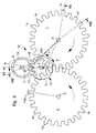
Les figures 1 à 4 sont des vues en plan de quatre phases successives
de l'échappement selon l'invention. L'échappement 10 est disposé, comme
cela est connu, entre un rouage et un balancier-spiral d'un garde-temps. Par
définition, le rouage ou finissage est l'ensemble des roues et pignons qui, d'un
barillet, transmet la force motrice à une roue d'échappement. En figure 1 le
rouage est représenté par sa dernière roue 8, associée au pignon 36. La roue
8 entraíne une première roue 6 d'échappement ou d'impulsion par le pignon
35 qui lui est solidaire. La première roue 6 engrène avec une second roue 7
d'échappement ou d'impulsion. On remarquera ici que la roue 8 pourrait
entraíner la seconde roue 7 à la place de la première roue 6. Les figures 1 à 4
montrent aussi des premier et second plateaux 9 et 11 solidaires d'un arbre
commun 1 auquel est attaché un balancier-spiral (non représenté). Comme le
montrent les figures, les première et seconde roues 6 et 7 ainsi que le premier
plateau 9 sont pourvus de moyens permettant au premier plateau 9 de
recevoir des impulsions directes délivrées alternativement par les première et
seconde roues 6 et 7 en vue d'entretenir les oscillations du balancier. De
même, les figures montrent que le second plateau 11 est pourvu de moyens
pour entraíner une bascule de blocage 12 arrangée pour bloquer
alternativement lesdites première et seconde roues 6 et 7.Figures 1 to 4 are plan views of four successive phases
of the exhaust according to the invention. The
Le paragraphe ci-dessus est une définition du nouvel échappement selon son acception la plus large. On va examiner maintenant un mode d'exécution particulier répondant à cette définition, ce mode d'exécution étant illustré par les mêmes figures 1 à 4, ainsi que par les figures 5 à 7 qui sont des coupes pratiquées dans les figures en plan 1 et 3.The above paragraph is a definition of the new exhaust in its broadest sense. We will now examine a mode of specific execution corresponding to this definition, this mode of execution being illustrated by the same figures 1 to 4, as well as by figures 5 to 7 which are sections made in the plan figures 1 and 3.
Les figures 1 à 4 montrent que les première et seconde roues
d'impulsion 6 et 7 possèdent une denture identique et ont un même diamètre.
Cette denture est faite d'un nombre restreint (ici cinq) de dents longues
référencées 13 pour la roue 6 et 14 pour la roue 7. Les dents longues 13 de
la roue 6 sont séparées chacune par une pluralité de dents courtes 15 (ici
quatre). De même, les dents longues 14 de la roue 7 sont séparées chacune
par une pluralité de dents courtes 16 (ici quatre). Le premier plateau 9,
solidaire de l'axe 1, auquel est attachée l'extrémité intérieure du spiral (non
représenté), comporte des première et seconde oreilles 17 et 18. La première
oreille 17 est arrangée pour recevoir une impulsion délivrée par une dent
longue 13a de la première roue 6 pour entraíner le balancier (non représenté),
supporté par l'axe 1, dans un premier sens A comme cela peut être déduit de
la figure 1. De même la seconde oreille 18 est arrangée pour recevoir une
impulsion délivrée par une dent longue 14a de la seconde roue 7 pour
entraíner le balancier dans un second sens B, inverse au premier sens A,
comme cela est apparent à la figure 3. Les figures 1 à 4 montrent encore
que le second plateau 11, solidaire de l'axe 1 comporte un disque 19 d'où
émerge un doigt 20. Ce doigt 20 est susceptible d'entraíner la bascule de
blocage 12 (voir figure 3) alternativement dans un premier sens E pour
bloquer la première roue 6 par l'une de ses dents longues 13, puis dans un
second sens F, inverse au premier sens E, pour bloquer la seconde roue 7 par
l'une de ses dents longues 14. La première situation de blocage est montrée
en figure 4 et la seconde en figure 2.Figures 1 to 4 show that the first and
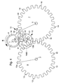
Reste à décrire un mode d'exécution de la bascule de blocage 12. Les
figures 1 à 4 montrent que cette bascule 12 est faite d'un disque 21 pivotant
sur un axe 2. Dans ce disque 31 sont taillées deux dents 22 et 23 entre
lesquelles peut pénétrer le doigt 20 du second plateau 11 pour faire pivoter la
bascule. Le disque 21 de la bascule 12 porte un excentrique ou ergot 33
contre lequel viennent buter alternativement les dents longues 13 et 14 des
première et seconde roues 6 et 7, comme cela est apparent aux figures 4 et
2 respectivement.It remains to describe an embodiment of the blocking
Un mode d'exécution du nouvel échappement ayant été décrit ci-dessus ainsi que les fonctions remplies par les diverses pièces composant cet échappement, on va passer en revue maintenant son mode de fonctionnement proprement dit en décrivant un cycle de marche complet. On examinera tour à tour les figures 1 à 4 qui montrent quatre phases importantes de ce cycle.An embodiment of the new exhaust having been described above as well as the functions performed by the various parts making up this exhaust, we will now review its mode of proper operation by describing a complete walking cycle. We will examine in turn Figures 1 to 4 which show four phases important of this cycle.
On suppose le ressort du barillet complètement détendu. Le mécanisme
est au repos. La dent longue 13a de la roue 6 est dégagée de l'ergot 33. Le
doigt 20 du second plateau 11 est engagé entre les dents 22 et 23 du disque
21 formant la bascule 12. L'oreille 17 du premier plateau 9 est en position
pour recevoir la dent 13a de la première roue 6. A partir de cette situation,
et si l'on remonte le ressort du barillet, la première roue 6 se met à tourner
dans le sens de la flèche M ce qui entraíne la seconde roue 7 dans le sens de
la flèche N. La dent longue 13a se met à tourner dans le sens de la flèche M,
rencontre l'oreille 17 et fait tourner les premier et second plateaux 9 et 11
dans le sens de la flèche A ce qui donne une impulsion directe au balancier et
initie la première alternance dudit balancier.Suppose the spring of the barrel is completely relaxed. The mechanism
is at rest. The
La rotation du second plateau 11 a entraíné la bascule 12 dans un
sens antihoraire F de sorte que son ergot 33 se trouve alors sur le chemin de
la dent longue 14a de la seconde roue 7. Ainsi la roue 7 se bloque, ce qui
entraíne aussi le blocage de la roue 6. Arrivé en fin de première alternance, le
sens de rotation du balancier s'inverse. La second alternance commence alors
dans le sens de la flèche B ce qui entraíne les premier et second plateaux 9 et
11 dans le même sens.The rotation of the
En tournant dans le sens de la flèche B, le doigt 20 du second plateau
11 s'introduit entre les dents 22 et 23 de la bascule 12 ce qui a pour effet de
faire tourner cette dernière ainsi que l'ergot 33 qui lui est lié dans le sens de la
flèche E. La dent longue 14a, qui était alors appuyée contre cet ergot, se
trouve maintenant libre de poursuivre sa course et de rencontrer l'oreille 18
du premier plateau 9 pour donner une nouvelle impulsion au balancier.By turning in the direction of arrow B, the
Après l'impulsion reçue, le second plateau 11 continue sa course dans
le sens de la flèche B et entraíne la bascule 12 dans le sens horaire de sorte
que son ergot 33 se trouve alors sur le chemin de la dent longue 13b de la
première roue 6. Ainsi, à son tour, la roue 6 se bloque, ce qui entraíne aussi le
blocage de la roue 7. Le déblocage va s'opérer à la prochaine alternance du
balancier et le cycle peut recommencer.After the received pulse, the
Les figures 1 à 4 montrent que chacune des première et seconde roues
d'impulsion 6 et 7 porte vingt-cinq dents, dont cinq dents longues 13 et 14,
quatre dents courtes 15 et 16 étant intercalées entre deux dents longues.
Dans le cas où l'on dispose d'un balancier-spiral faisant huit alternances par
seconde (soit 28'800 alternances par heure) ce qui est habituel pour une
montre-bracelet, ce balancier fera 4 oscillations par seconde. Or, on peut
déduire de ce qui a été vu plus haut qu'une oscillation fait avancer la roue 6
de 360 degrés divisés par cinq dents longues soit un pas de 72 degrés. Il
résulte de cela que la roue 6 progresse de 4 pas par seconde soit de
4 x 72 = 288 degrés et finalement parcourt un tour de 360 degrés en
1,25 secondes.Figures 1 to 4 show that each of the first and
La figure 8 est un agrandissement de la zone VIII montrée en figure 4
et met l'accent sur la façon dont s'appuie la dent longue 13b sur l'ergot 33
de la bascule 12. Cette figure 8 montre bien que la face 34 de l'ergot 33, face
contre laquelle viennent buter alternativement les dents longues 13 et 14, est
formée en arc de cercle, le rayon R de cet arc passant par le centre de
pivotement 2 de la bascule 12.Figure 8 is an enlargement of zone VIII shown in Figure 4
and emphasizes how the
Ainsi, on comprendra que lorsque l'ergot 33 s'escamote lors de la
rotation de la bascule 12 dans le sens de la flèche G, il n'y a aucun recul de la
roue 6. En conclusion, le désavantage présenté par le recul dû au tirage de
l'échappement à ancre n'existe pas dans le nouvel échappement proposé.Thus, it will be understood that when the
Pour revenir à la bascule 12 montrée en figure 2, on observera que les
deux dents 22 et 23 taillées dans le disque 21 définissent trois espaces. Un
premier espace 30 est situé entre les deux dents 22 et 23. Dans cet espace
30 peut pénétrer le doigt 20 du second plateau 11 pour faire pivoter la
bascule. Des deuxième et troisième espaces 31 et 32 sont situés de part et
d'autre de la paire de dents 22 et 23, espaces dans lesquels peut pénétrer
alternativement, et de manière partielle, le disque 19 du second plateau 11,
ceci dans le but d'immobiliser la bascule après son pivotement. Ainsi comme
on le voit particulièrement bien en figure 2, le disque 19 du second plateau 11
pénètre partiellement dans l'espace 32 formé après la dent 23 de la bascule.
Cet artifice est important car dans la situation de blocage de la dent 14a par
l'ergot 33 de la bascule, il ne faudrait pas que cette bascule puisse tourner
intempestivement, par exemple sous l'effet d'un choc appliqué à la pièce
d'horlogerie.To return to the flip-
En résumé de tout ce qui a été dit plus haut, le nouvel échappement proposé présente tous les avantages des échappements connus tout en écartant leurs inconvénients. Ceci est dû en grande partie à l'utilisation exclusive de mobiles tournants présentant une géométrie conventionnelle en évitant l'emploi de leviers, ressorts ou plan inclinés, éléments perturbateurs d'un bon fonctionnement dynamique. Il en résulte un échappement nouveau d'une grande simplicité théorique où n'entrent en jeu que des pièces circulaires, des moments de forces, des vitesses périphériques et des inerties de mobiles à symétrie axiale. Ainsi, une telle construction a-t-elle permis d'éliminer la perte d'énergie au dégagement (recul), d'obtenir une impulsion directe dans les deux sens, de maintenir l'autodémarrage et de garantir la sécurité de fonctionnement par construction (renversement évité).In summary of all that has been said above, the new exhaust proposed has all the advantages of known exhausts while dismissing their drawbacks. This is largely due to the use exclusive of rotating mobiles with conventional geometry in avoiding the use of levers, springs or inclined planes, disturbing elements good dynamic operation. This results in a new exhaust of a great theoretical simplicity where only parts come into play circular, moments of force, peripheral speeds and inertias of axially symmetrical mobiles. Thus, such a construction allowed eliminate energy loss on release (recoil), obtain an impulse direct in both directions, to maintain the auto-start and to guarantee the operational safety by construction (overturning avoided).
Claims (6)
Priority Applications (4)
| Application Number | Priority Date | Filing Date | Title |
|---|---|---|---|
| DE69902990T DE69902990T2 (en) | 1999-03-31 | 1999-03-31 | Inhibition for timepieces |
| EP99106602A EP1041459B1 (en) | 1999-03-31 | 1999-03-31 | Escapement for timepiece |
| US09/531,170 US6301981B1 (en) | 1999-03-31 | 2000-03-21 | Escapement for a timekeeper |
| JP2000098062A JP2000304873A (en) | 1999-03-31 | 2000-03-31 | Escapement for clock |
Applications Claiming Priority (1)
| Application Number | Priority Date | Filing Date | Title |
|---|---|---|---|
| EP99106602A EP1041459B1 (en) | 1999-03-31 | 1999-03-31 | Escapement for timepiece |
Publications (2)
| Publication Number | Publication Date |
|---|---|
| EP1041459A1 true EP1041459A1 (en) | 2000-10-04 |
| EP1041459B1 EP1041459B1 (en) | 2002-09-18 |
Family
ID=8237897
Family Applications (1)
| Application Number | Title | Priority Date | Filing Date |
|---|---|---|---|
| EP99106602A Expired - Lifetime EP1041459B1 (en) | 1999-03-31 | 1999-03-31 | Escapement for timepiece |
Country Status (4)
| Country | Link |
|---|---|
| US (1) | US6301981B1 (en) |
| EP (1) | EP1041459B1 (en) |
| JP (1) | JP2000304873A (en) |
| DE (1) | DE69902990T2 (en) |
Cited By (4)
| Publication number | Priority date | Publication date | Assignee | Title |
|---|---|---|---|---|
| EP1221637A1 (en) * | 2001-01-09 | 2002-07-10 | Ulysse Nardin S.A. | Escapement for timekeeper |
| EP1276021A1 (en) | 2001-06-26 | 2003-01-15 | Ulysse Nardin S.A. | Escape for timekeeper |
| EP1367462A1 (en) * | 2002-05-28 | 2003-12-03 | Ulysse Nardin S.A. | Escapement for timepiece |
| EP2487546A1 (en) * | 2011-02-11 | 2012-08-15 | Montres Journe S.A. | High-performance bi-axial escapement, or HPBE |
Families Citing this family (20)
| Publication number | Priority date | Publication date | Assignee | Title |
|---|---|---|---|---|
| US6948686B2 (en) | 2002-04-10 | 2005-09-27 | Walter Holemans | Constant rate deployment device |
| TW568209U (en) * | 2002-10-18 | 2003-12-21 | Lite On It Corp | Gear type linkage device with fool proof |
| CH700720B1 (en) * | 2003-06-23 | 2010-10-15 | Ronda Ag | Gear for watch movement and date display mechanism provided with such a gear. |
| ATE363673T1 (en) * | 2003-12-04 | 2007-06-15 | Montres Breguet Sa | CHRONOMETER ESCAPEMENT FOR WRISTWATCHES |
| US7430937B2 (en) * | 2004-01-16 | 2008-10-07 | Maytag Corporation | Rack and pinion stabilizer system |
| EP1708047B1 (en) * | 2005-03-30 | 2008-03-26 | Montres Breguet S.A. | Detent escapement for timepieces |
| DE602005005632T2 (en) * | 2005-03-30 | 2009-04-16 | Montres Breguet S.A. | Chronometer escapement for watches |
| CN101238419B (en) * | 2005-07-04 | 2010-04-07 | 蒙特雷布勒盖股份有限公司 | High-performance pin barrel escapement |
| EP1770452A1 (en) * | 2005-09-30 | 2007-04-04 | Peter Baumberger | Detent escapement for timepieces |
| EP1967919B1 (en) * | 2007-03-09 | 2009-06-03 | ETA SA Manufacture Horlogère Suisse | Exhaust with tangential impulses |
| EP1983388B1 (en) * | 2007-04-18 | 2010-01-20 | ETA SA Manufacture Horlogère Suisse | Direct-pulse escapement for timepiece |
| DE602007003445D1 (en) * | 2007-04-18 | 2010-01-07 | Eta Sa Mft Horlogere Suisse | Inhibition, which includes two escapement wheels |
| ATE447731T1 (en) * | 2007-04-18 | 2009-11-15 | Eta Sa Mft Horlogere Suisse | ANCHOR ESCAPEMENT COMPRISING TWO ESCUPATION GEARS |
| EP2199875B1 (en) * | 2008-12-16 | 2014-09-24 | Rolex Sa | Detent escapement |
| JP5614963B2 (en) * | 2009-09-25 | 2014-10-29 | 株式会社ケーヒン | Driving force transmission mechanism |
| EP2363762B1 (en) * | 2010-03-04 | 2017-11-22 | Montres Breguet SA | Timepiece including a high-frequency mechanical movement |
| CN104364719B (en) * | 2012-06-07 | 2017-03-15 | 迪特拉有限公司 | Release for timer |
| US9746829B2 (en) * | 2013-12-23 | 2017-08-29 | Nivarox-Far S.A. | Contactless cylinder escapement mechanism for timepieces |
| JP6206877B2 (en) * | 2014-03-06 | 2017-10-04 | セイコーインスツル株式会社 | Escapement, watch movement and watch |
| JP6347439B2 (en) * | 2014-03-06 | 2018-06-27 | セイコーインスツル株式会社 | Escapement, watch movement and watch |
Citations (2)
| Publication number | Priority date | Publication date | Assignee | Title |
|---|---|---|---|---|
| CH263069A (en) * | 1944-03-22 | 1949-08-15 | Jeanneret Abram Louis | Exhaust. |
| DE2458503A1 (en) * | 1974-12-11 | 1976-06-16 | Graesslin Feinwerktech | Stop watch or timer restraint mechanism - uses two congruent wheels with meshing peripheral teeth of two wheels |
Family Cites Families (2)
| Publication number | Priority date | Publication date | Assignee | Title |
|---|---|---|---|---|
| US2354020A (en) * | 1941-07-26 | 1944-07-18 | Mefina Sa | Clockwork escapement |
| US3143848A (en) * | 1957-01-02 | 1964-08-11 | Hamilton Watch Co | Indexing mechanism |
-
1999
- 1999-03-31 DE DE69902990T patent/DE69902990T2/en not_active Expired - Fee Related
- 1999-03-31 EP EP99106602A patent/EP1041459B1/en not_active Expired - Lifetime
-
2000
- 2000-03-21 US US09/531,170 patent/US6301981B1/en not_active Expired - Fee Related
- 2000-03-31 JP JP2000098062A patent/JP2000304873A/en active Pending
Patent Citations (2)
| Publication number | Priority date | Publication date | Assignee | Title |
|---|---|---|---|---|
| CH263069A (en) * | 1944-03-22 | 1949-08-15 | Jeanneret Abram Louis | Exhaust. |
| DE2458503A1 (en) * | 1974-12-11 | 1976-06-16 | Graesslin Feinwerktech | Stop watch or timer restraint mechanism - uses two congruent wheels with meshing peripheral teeth of two wheels |
Cited By (7)
| Publication number | Priority date | Publication date | Assignee | Title |
|---|---|---|---|---|
| EP1221637A1 (en) * | 2001-01-09 | 2002-07-10 | Ulysse Nardin S.A. | Escapement for timekeeper |
| US6708576B2 (en) | 2001-01-09 | 2004-03-23 | Ulysse Nardin S.A. | Escapement for a timekeeper |
| EP1276021A1 (en) | 2001-06-26 | 2003-01-15 | Ulysse Nardin S.A. | Escape for timekeeper |
| EP1367462A1 (en) * | 2002-05-28 | 2003-12-03 | Ulysse Nardin S.A. | Escapement for timepiece |
| US6802645B2 (en) | 2002-05-28 | 2004-10-12 | Ulysse Nardin S.A. | Escapement for timekeeper |
| EP2487546A1 (en) * | 2011-02-11 | 2012-08-15 | Montres Journe S.A. | High-performance bi-axial escapement, or HPBE |
| US8562205B2 (en) | 2011-02-11 | 2013-10-22 | Montres Journe S.A. | Bi-axial high-performance escapement, or BHPE (EBHP) |
Also Published As
| Publication number | Publication date |
|---|---|
| DE69902990T2 (en) | 2003-05-22 |
| US6301981B1 (en) | 2001-10-16 |
| EP1041459B1 (en) | 2002-09-18 |
| JP2000304873A (en) | 2000-11-02 |
| DE69902990D1 (en) | 2002-10-24 |
Similar Documents
| Publication | Publication Date | Title |
|---|---|---|
| EP1041459B1 (en) | Escapement for timepiece | |
| EP2548084B1 (en) | Movement for a timepiece with equalizing winding mechanism | |
| EP2221676B1 (en) | Timepiece including a chronograph and a watch | |
| EP1983388B1 (en) | Direct-pulse escapement for timepiece | |
| EP3021175B1 (en) | Split-seconds device with epicycloidal train for a timepiece | |
| EP1544689B1 (en) | Detent escapement for watches | |
| EP1538491B1 (en) | Detent escapement for watches | |
| EP3001258B1 (en) | Ringing mechanism with differentiated ringtones | |
| EP1221637B1 (en) | Escapement for timekeeper | |
| EP1367462B1 (en) | Escapement for timepiece | |
| EP1801668B1 (en) | Anti-tripping device for timepiece escapement | |
| EP3584641B1 (en) | Automatically starting and secured detent escapement for timepieces | |
| EP2096504B1 (en) | Mechanism for displaying dead seconds | |
| WO2017125194A1 (en) | Coup perdu escapement mechanism | |
| EP1276021B1 (en) | Escape for timekeeper | |
| EP4002016A1 (en) | Watch with mechanical movement with force control mechanism | |
| CH712288B1 (en) | Bi-functional dart, locking and securing device for a timepiece, and watch escapement. | |
| EP1879085B1 (en) | Escapement | |
| EP1522001B1 (en) | Escapement device | |
| EP4303664A1 (en) | Timepiece movement and timepiece comprising such a movement | |
| EP4198641A1 (en) | Natural escapement for timepiece movement and timepiece movement comprising such an escapement | |
| EP4053642A1 (en) | Natural escapement for timepiece movement and timepiece movement comprising such an escapement | |
| EP4053643A1 (en) | Natural escapement for timepiece movement and timepiece movement comprising such an escapement | |
| CH718076A2 (en) | Mechanical movement watch with force control mechanism. | |
| EP3979008A1 (en) | Watch with mechanical movement with force control mechanism |
Legal Events
| Date | Code | Title | Description |
|---|---|---|---|
| PUAI | Public reference made under article 153(3) epc to a published international application that has entered the european phase |
Free format text: ORIGINAL CODE: 0009012 |
|
| AK | Designated contracting states |
Kind code of ref document: A1 Designated state(s): CH DE FR GB IT LI |
|
| AX | Request for extension of the european patent |
Free format text: AL;LT;LV;MK;RO;SI |
|
| 17P | Request for examination filed |
Effective date: 20001129 |
|
| AKX | Designation fees paid |
Free format text: CH DE FR GB IT LI |
|
| GRAG | Despatch of communication of intention to grant |
Free format text: ORIGINAL CODE: EPIDOS AGRA |
|
| 17Q | First examination report despatched |
Effective date: 20010910 |
|
| GRAG | Despatch of communication of intention to grant |
Free format text: ORIGINAL CODE: EPIDOS AGRA |
|
| GRAH | Despatch of communication of intention to grant a patent |
Free format text: ORIGINAL CODE: EPIDOS IGRA |
|
| GRAH | Despatch of communication of intention to grant a patent |
Free format text: ORIGINAL CODE: EPIDOS IGRA |
|
| GRAA | (expected) grant |
Free format text: ORIGINAL CODE: 0009210 |
|
| AK | Designated contracting states |
Kind code of ref document: B1 Designated state(s): CH DE FR GB IT LI |
|
| REG | Reference to a national code |
Ref country code: GB Ref legal event code: FG4D Free format text: NOT ENGLISH |
|
| REG | Reference to a national code |
Ref country code: CH Ref legal event code: EP |
|
| REF | Corresponds to: |
Ref document number: 69902990 Country of ref document: DE Date of ref document: 20021024 |
|
| GBT | Gb: translation of ep patent filed (gb section 77(6)(a)/1977) |
Effective date: 20030122 |
|
| PGFP | Annual fee paid to national office [announced via postgrant information from national office to epo] |
Ref country code: GB Payment date: 20030225 Year of fee payment: 5 |
|
| PGFP | Annual fee paid to national office [announced via postgrant information from national office to epo] |
Ref country code: DE Payment date: 20030314 Year of fee payment: 5 |
|
| REG | Reference to a national code |
Ref country code: CH Ref legal event code: NV Representative=s name: ICB INGENIEURS CONSEILS EN BREVETS SA |
|
| PGFP | Annual fee paid to national office [announced via postgrant information from national office to epo] |
Ref country code: FR Payment date: 20030326 Year of fee payment: 5 |
|
| PLBE | No opposition filed within time limit |
Free format text: ORIGINAL CODE: 0009261 |
|
| STAA | Information on the status of an ep patent application or granted ep patent |
Free format text: STATUS: NO OPPOSITION FILED WITHIN TIME LIMIT |
|
| 26N | No opposition filed |
Effective date: 20030619 |
|
| PG25 | Lapsed in a contracting state [announced via postgrant information from national office to epo] |
Ref country code: GB Free format text: LAPSE BECAUSE OF NON-PAYMENT OF DUE FEES Effective date: 20040331 |
|
| PG25 | Lapsed in a contracting state [announced via postgrant information from national office to epo] |
Ref country code: DE Free format text: LAPSE BECAUSE OF NON-PAYMENT OF DUE FEES Effective date: 20041001 |
|
| GBPC | Gb: european patent ceased through non-payment of renewal fee | ||
| PG25 | Lapsed in a contracting state [announced via postgrant information from national office to epo] |
Ref country code: FR Free format text: LAPSE BECAUSE OF NON-PAYMENT OF DUE FEES Effective date: 20041130 |
|
| REG | Reference to a national code |
Ref country code: FR Ref legal event code: ST |
|
| PG25 | Lapsed in a contracting state [announced via postgrant information from national office to epo] |
Ref country code: IT Free format text: LAPSE BECAUSE OF NON-PAYMENT OF DUE FEES Effective date: 20050331 |
|
| REG | Reference to a national code |
Ref country code: CH Ref legal event code: PK Free format text: GLN GRESSET & LAESSER A ETE ENREGISTRE COMME MANDATAIRE PAR ERREUR. Ref country code: CH Ref legal event code: NV Representative=s name: GLN S.A. Ref country code: CH Ref legal event code: NV Representative=s name: GLN GRESSET & LAESSER NEUCHATEL CABINET DE CONSEIL |
|
| PGFP | Annual fee paid to national office [announced via postgrant information from national office to epo] |
Ref country code: CH Payment date: 20080328 Year of fee payment: 10 |
|
| REG | Reference to a national code |
Ref country code: CH Ref legal event code: PK |
|
| REG | Reference to a national code |
Ref country code: CH Ref legal event code: PL |
|
| PG25 | Lapsed in a contracting state [announced via postgrant information from national office to epo] |
Ref country code: LI Free format text: LAPSE BECAUSE OF NON-PAYMENT OF DUE FEES Effective date: 20090331 Ref country code: CH Free format text: LAPSE BECAUSE OF NON-PAYMENT OF DUE FEES Effective date: 20090331 |