EP1041250B1 - Hitzeschild für eine Gasturbine - Google Patents
Hitzeschild für eine Gasturbine Download PDFInfo
- Publication number
- EP1041250B1 EP1041250B1 EP00810264A EP00810264A EP1041250B1 EP 1041250 B1 EP1041250 B1 EP 1041250B1 EP 00810264 A EP00810264 A EP 00810264A EP 00810264 A EP00810264 A EP 00810264A EP 1041250 B1 EP1041250 B1 EP 1041250B1
- Authority
- EP
- European Patent Office
- Prior art keywords
- heat
- curvature
- heat shield
- shield
- arms
- Prior art date
- Legal status (The legal status is an assumption and is not a legal conclusion. Google has not performed a legal analysis and makes no representation as to the accuracy of the status listed.)
- Expired - Lifetime
Links
Images


Classifications
-
- F—MECHANICAL ENGINEERING; LIGHTING; HEATING; WEAPONS; BLASTING
- F01—MACHINES OR ENGINES IN GENERAL; ENGINE PLANTS IN GENERAL; STEAM ENGINES
- F01D—NON-POSITIVE DISPLACEMENT MACHINES OR ENGINES, e.g. STEAM TURBINES
- F01D9/00—Stators
-
- F—MECHANICAL ENGINEERING; LIGHTING; HEATING; WEAPONS; BLASTING
- F01—MACHINES OR ENGINES IN GENERAL; ENGINE PLANTS IN GENERAL; STEAM ENGINES
- F01D—NON-POSITIVE DISPLACEMENT MACHINES OR ENGINES, e.g. STEAM TURBINES
- F01D11/00—Preventing or minimising internal leakage of working-fluid, e.g. between stages
- F01D11/08—Preventing or minimising internal leakage of working-fluid, e.g. between stages for sealing space between rotor blade tips and stator
-
- F—MECHANICAL ENGINEERING; LIGHTING; HEATING; WEAPONS; BLASTING
- F02—COMBUSTION ENGINES; HOT-GAS OR COMBUSTION-PRODUCT ENGINE PLANTS
- F02C—GAS-TURBINE PLANTS; AIR INTAKES FOR JET-PROPULSION PLANTS; CONTROLLING FUEL SUPPLY IN AIR-BREATHING JET-PROPULSION PLANTS
- F02C7/00—Features, components parts, details or accessories, not provided for in, or of interest apart form groups F02C1/00 - F02C6/00; Air intakes for jet-propulsion plants
- F02C7/24—Heat or noise insulation
-
- F—MECHANICAL ENGINEERING; LIGHTING; HEATING; WEAPONS; BLASTING
- F23—COMBUSTION APPARATUS; COMBUSTION PROCESSES
- F23R—GENERATING COMBUSTION PRODUCTS OF HIGH PRESSURE OR HIGH VELOCITY, e.g. GAS-TURBINE COMBUSTION CHAMBERS
- F23R3/00—Continuous combustion chambers using liquid or gaseous fuel
- F23R3/002—Wall structures
-
- F—MECHANICAL ENGINEERING; LIGHTING; HEATING; WEAPONS; BLASTING
- F05—INDEXING SCHEMES RELATING TO ENGINES OR PUMPS IN VARIOUS SUBCLASSES OF CLASSES F01-F04
- F05D—INDEXING SCHEME FOR ASPECTS RELATING TO NON-POSITIVE-DISPLACEMENT MACHINES OR ENGINES, GAS-TURBINES OR JET-PROPULSION PLANTS
- F05D2240/00—Components
- F05D2240/10—Stators
- F05D2240/11—Shroud seal segments
-
- F—MECHANICAL ENGINEERING; LIGHTING; HEATING; WEAPONS; BLASTING
- F05—INDEXING SCHEMES RELATING TO ENGINES OR PUMPS IN VARIOUS SUBCLASSES OF CLASSES F01-F04
- F05D—INDEXING SCHEME FOR ASPECTS RELATING TO NON-POSITIVE-DISPLACEMENT MACHINES OR ENGINES, GAS-TURBINES OR JET-PROPULSION PLANTS
- F05D2260/00—Function
- F05D2260/20—Heat transfer, e.g. cooling
- F05D2260/231—Preventing heat transfer
Definitions
- the present invention relates to the field of gas turbines. It relates to a heat shield for a gas turbine, which heat shield in particular the rotating blades of a stage of the gas turbine surrounds annular and of a plurality of circumferentially arranged in succession, circular segment curved and cooled from the outside heat shield segments consists whose longitudinal sides as extending in the circumferential direction, corresponding curved rails each having a first protruding in the axial direction Arm are formed, and for attachment to the housing of the gas turbine with the first arms each in an annular space of constant width are stored.
- Such a segmented heat shield is for example from the document US-A-5,071,313 known.
- a heat shield in a gas turbine generally has the function of the flow space for limiting the hot gas and the housings and supporting structures the gas turbine before the hot gas and an excessive heat input to protect. For this it is necessary to cool the heat shield, as for example in US-A-3,864,056.
- the cooling usually by the influx of the heat shield with cooling air on the hot gas facing away Page causes temperature differences in the heat shield and so that internal thermal stresses that stress the heat shield excessive can.
- EP-B1-0 728 258 has been proposed, the segments of the heat shield by means of integrally formed Store hooks on the housing, with first hooks in the middle of the segment are hung with little play, while second hooks at the ends of the Segments are hung with so much play that when thermally induced Extension of the segments and the associated displacement of the second Hook no mechanical stresses generated by the suspension.
- the known game-bearing storage by means of the first and second hook has however, several disadvantages: because the central fixation of the segments through the first hook is insufficient to secure the segments in total in their position fix, in addition, a band (62 in Fig. 2 of EP-B1-0 728 258) must be inserted be used to keep the segments in a stable position. This requires Production and installation of the heat shield a considerable additional effort.
- the object is solved by the entirety of the features of claim 1.
- the essence of the invention is the individual segments of the heat shield on the longitudinal sides continuous rails at their respective ends practically to store without play, while provided in the central area sufficient play is that at thermally induced decurling of segments the average Move area without disabilities in the radial direction.
- the support points The segments at the segment ends form pivot points for the Stretch or warp.
- a first preferred embodiment of the heat shield according to the invention is characterized in that the intermediate spaces each have an outer radius of curvature and an inner radius of curvature that the first Arms in the cold state of the heat shield segment each have an outer radius of curvature and have an inner radius of curvature, and that the two outer radii of curvature are substantially the same and the inner Radius of curvature of the first arms is smaller than the inner radius of curvature the spaces between.
- the required clearance in Central region of the segments generated by different radii of curvature the segments can be easily adjusted with a grinding wheel on different Edit radii of curvature.
- paragraphs or Discrepancies in the marginal area of the segments avoided at which unfavorable mechanical stress conditions can occur.
- a preferred development of this embodiment is characterized from that the inner radius of curvature of the first arms is chosen so that he due to the thermal distortion of the heat shield segment when heated goes to the operating temperature of the gas turbine in a radius of curvature, which is approximately equal to the inner radius of curvature of the spaces is.
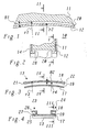
- FIGs. 1 and 2 in longitudinal section, i. in a section transverse to the turbine axis (Sectional plane I-I in Fig. 2), and in cross-section (sectional plane II - II in Fig. 1), the section of an annular heat shield support 11 of a gas turbine 10 with formed by laterally arranged brackets 12 and 14 curved Gaps 20 and 28 for storage or holding a heat shield segment reproduced according to the invention.
- the annular support 11, which with the housing of the gas turbine 10 is in communication or even part of the housing may be surrounding a (not shown) equipped with blades part the rotor of the gas turbine 10, as shown for example in Fig. 1 of US-A-5,071,313 is shown.
- brackets 12 and 14 which are formed in the present example as separate components, But just as well as part of the carrier 11 may be, grab with L-shaped inwardly bent ends from both sides under the carrier 11.
- the brackets 12 and 14 are for dismantling the heat shield segments. They are also segmented, wherein a clip segment for one or more heat shield segment (s) provided can be.
- a heat shield segment 13 can now be used, as in FIGS. 3 and 4 in longitudinal section (sectional plane III-III in FIG. 4) or in cross section (section plane IV - IV in Fig. 3) is shown.
- the heat shield segment 13 consists essentially of a rectangular, curved in the longitudinal direction Plate made of a heat-resistant material, on whose long sides (similar as in Fig. 3 of US-A-5,071,313) rails 23, 24 for attachment of the segment in the support structure of Figs. 1 and 2 are formed.
- the upper and lower arms 18, 17 and 26, 25 are each spaced apart so that between them a curved slot 19 and 27 remains free, in which the brackets 12, 14 bent with their L-shaped Ends can intervene.
- To form the (closed ring) Heat shield is a corresponding plurality of heat shield segments 13 in Circumferentially secured one behind the other on the carrier 11.
- FIG. 5 shows the Fig. 1 and 3 comparable longitudinal section through the arrangement (sectional plane V - V in FIG. 6 or center plane 16 of the heat shield segment 13)
- Fig. 6 shows the cross section in the Sectional plane VI - VI according to FIG. 5
- FIG. 7 shows the cross section in the sectional plane VII - VII according to FIG. 5.
- Die outer radii r1 and r3 are related to the same center, while the center for the inner radius r4 opposite the center for the inner Radius r2 is shifted radially outward so far that the (maximum) width B2 of the upper arms 18, 26 on the end faces 21, 22 of the heat shield segment thirteenth is approximately equal to the width B1 of the spaces 20, 28. This is achieved that the heat shield segment 13 at the two (opposite) end faces 21, 22 practically free of play in the spaces 20, 28 held and stored while there is increasing play towards the middle.
- Fig. 5-7 refers to the cold state of the gas turbine.
- the inside of the heat shield segments 13 with Hot gas applied while in between the heat shield segment 13 and the Carrier 11 formed cavity 15 (Fig. 6 and 7) for cooling the segments Cooling air flows in and bounces on the outside of the segments.
- FIGS. 5 and 6 comparable sectional views 8th and FIG. 9 is shown.
- the resting on the brackets 12, 14 edges on the end faces 21, 22 of the heat shield segments 13 form two pivot points while the segments in the middle part move radially inwards.
- the lower arms 17, 25 of the heat shield segment 13 can be made largely independent, provided they do not interfere with the described process of warping. They serve essentially the shielding of the brackets 12, 14 in front of the hot gases.
Landscapes
- Engineering & Computer Science (AREA)
- Mechanical Engineering (AREA)
- General Engineering & Computer Science (AREA)
- Chemical & Material Sciences (AREA)
- Combustion & Propulsion (AREA)
- Turbine Rotor Nozzle Sealing (AREA)
Description
- Fig. 1
- im Längsschnitt, d.h. in einem Schnitt quer zur Turbinenachse, den Ausschnitt eines ringförmigen Hitzeschild-Trägers einer Gasturbine mit einem durch eine Klammer gebildeten gekrümmten Zwischenraum zur Lagerung eines Hitzeschildsegmentes nach der Erfindung;
- Fig. 2
- den Schnitt durch die Anordnung nach Fig. 1 in der Ebene II - II;
- Fig. 3
- im Längsschnitt den Randbereich eines Hitzeschildsegments gemäss einem bevorzugten Ausführungsbeispiel der Erfindung, welches zur Aufnahme in die Befestigungsvorrichtung nach Fig. 1 bzw. Fig. 2 vorgesehen ist.
- Fig. 4
- einen Querschnitt durch das Hitzeschildsegment gemäss Fig. 3 in der Ebene IV - IV;
- Fig. 5
- eine Schnittdarstellung der Befestigungsvorrichtung nach Fig. 1 mit eingesetztem Hitzeschildsegment gemäss Fig. 3 im kalten Zustand;
- Fig. 6
- den Querschnitt durch die Anordnung nach Fig. 5 in der Ebene VII -VII;
- Fig. 7
- den Querschnitt durch die Anordnung nach Fig. 5 in der Ebene VI -VI;
- Fig. 8
- eine Schnittdarstellung der Befestigungsvorrichtung nach Fig. 1 mit eingesetztem Hitzeschildsegment gemäss Fig. 3 im betriebsmässigen, warmen Zustand; und
- Fig. 9
- den Querschnitt durch die Anordnung nach Fig. 8 in der Ebene IX - IX.
- 10
- Gasturbine
- 11
- Träger (Gehäuse)
- 12,14
- Klammer
- 13
- Hitzeschildsegment
- 15
- Hohlraum
- 16
- Mittelebene
- 17,18
- Arm
- 19
- Schlitz
- 20,28
- Zwischenraum (ringförmig)
- 21,22
- Stirnseite (Hitzeschildsegment)
- 23,24
- Schiene
- 25,26
- Arm
- 27
- Schlitz
- B1
- Breite (Zwischenraum 20)
- B2
- Breite (Arm 18 bzw. 26))
- r1,..,r4
- Krümmungsradius
Claims (5)
- Hitzeschild für eine Gasturbine (10), welches Hitzeschild insbesondere die rotierenden Schaufeln einer Stufe der Gasturbine (10) ringförmig umschliesst und aus einer Mehrzahl von in Umfangsrichtung hintereinander angeordneten, kreissegmentförmig gekrümmten und von aussen gekühlten Hitzeschildsegmenten (13) besteht, deren Längsseiten als in Umfangsrichtung verlaufende, entsprechend gekrümmte Schienen (23, 24) mit jeweils einem in axialer Richtung abstehenden ersten Arm (18 bzw. 26) ausgebildet sind, und die zur Befestigung am Gehäuse der Gasturbine (10) mit den ersten Armen (18, 26) jeweils in einem ringförmigen Zwischenraum (20, 28) konstanter Breite (B2) gelagert sind, dadurch gekennzeichnet, dass die ersten Arme (18, 26) eine in Umfangsrichtung variierende Breite (B2) aufweisen, welche an den Stirnseiten (21, 22) des Hitzeschildsegments (13) im wesentlichen gleich der Breite (B1) der Zwischenräume (20, 28) ist und zur Mittelebene (16) des Hitzeschildsegments (13) hin derart abnimmt, dass sich das Hitzeschildsegment (13) bei thermischer Belastung mit seinen ersten Armen (18, 26) in einem vorgegebenen Bereich in den Zwischenräumen (20, 28) ungehindert entkrümmen kann.
- Hitzeschild nach Anspruch 1, dadurch gekennzeichnet, dass die Zwischenräume (20, 28) jeweils einen äusseren Krümmungsradius (r1) und einen inneren Krümmungsradius (r2) aufweisen, dass die ersten Arme (18, 26) im kalten Zustand des Hitzeschildsegments (13) jeweils einen äusseren Krümmungsradius (r3) und einen inneren Krümmungsradius (r4) aufweisen, und dass die beiden äusseren Krümmungsradien (r1, r3) im wesentlichen gleich sind und der innere Krümmungsradius (r4) der ersten Arme (18, 26) kleiner ist, als der innere Krümmungsradius (r2) der Zwischenräume (20, 28).
- Hitzeschild nach Anspruch 2, dadurch gekennzeichnet, dass der innere Krümmungsradius (r4) der ersten Arme (18, 26) so gewählt ist, dass er durch die thermisch bedingte Entkrümmung des Hitzeschildsegments (13) bei Erwärmung auf die Betriebstemperatur der Gasturbine (10) in einen Krümmungsradius übergeht, welcher ungefähr gleich dem inneren Krümmungsradius (r2) der Zwischenräume (20, 28) ist.
- Hitzeschild nach einem der Ansprüche 1 bis 3, dadurch gekennzeichnet, dass die Zwischenräume (20, 28) jeweils zwischen einem ringförmigen Träger (11) für die Hitzeschildsegmente (13) und zwei Klammern (12, 14) gebildet werden, welche auf beiden Seiten des Trägers (11) angeordnet sind und mit L-förmig nach innen abgebogenen Enden von beiden Seiten unter den Träger (11) greifen.
- Hitzeschild nach Anspruch 4, dadurch gekennzeichnet, dass an den Schienen (23, 24) der Hitzeschildsegmente (13) unterhalb des ersten Armes 18 bzw. 26) jeweils ein davon beabstandeter, parallel verlaufender zweiter Arm (17 bzw. 25) vorgesehen ist, so dass zwischen den parallelen ersten und zweiten Armen (17, 18 bzw. 25, 26) Schlitze (19 bzw. 27) gebildet werden, und dass die Klammern (12, 14) mit den L-fömig abgebogenen Enden in die Schlitze (19, 27) eingreifen.
Applications Claiming Priority (2)
| Application Number | Priority Date | Filing Date | Title |
|---|---|---|---|
| DE19915049A DE19915049A1 (de) | 1999-04-01 | 1999-04-01 | Hitzeschild für eine Gasturbine |
| DE19915049 | 1999-04-01 |
Publications (3)
| Publication Number | Publication Date |
|---|---|
| EP1041250A2 EP1041250A2 (de) | 2000-10-04 |
| EP1041250A3 EP1041250A3 (de) | 2002-07-31 |
| EP1041250B1 true EP1041250B1 (de) | 2005-10-26 |
Family
ID=7903366
Family Applications (1)
| Application Number | Title | Priority Date | Filing Date |
|---|---|---|---|
| EP00810264A Expired - Lifetime EP1041250B1 (de) | 1999-04-01 | 2000-03-29 | Hitzeschild für eine Gasturbine |
Country Status (4)
| Country | Link |
|---|---|
| US (1) | US6361273B1 (de) |
| EP (1) | EP1041250B1 (de) |
| CN (1) | CN1250865C (de) |
| DE (2) | DE19915049A1 (de) |
Families Citing this family (25)
| Publication number | Priority date | Publication date | Assignee | Title |
|---|---|---|---|---|
| US6808363B2 (en) * | 2002-12-20 | 2004-10-26 | General Electric Company | Shroud segment and assembly with circumferential seal at a planar segment surface |
| FR2867224B1 (fr) * | 2004-03-04 | 2006-05-19 | Snecma Moteurs | Dispositif de maintien axial de secteur d'entretoise pour anneau d'une turbine haute-pression de turbomachine |
| ITMI20041781A1 (it) | 2004-09-17 | 2004-12-17 | Nuovo Pignone Spa | Dispositivo di protezione per uno statore di una turbina |
| ITMI20041780A1 (it) * | 2004-09-17 | 2004-12-17 | Nuovo Pignone Spa | Dispositivo di protezione per uno statore di una turbina |
| US7448846B2 (en) * | 2005-08-06 | 2008-11-11 | General Electric Company | Thermally compliant turbine shroud mounting |
| US7452183B2 (en) * | 2005-08-06 | 2008-11-18 | General Electric Company | Thermally compliant turbine shroud assembly |
| US7442004B2 (en) * | 2005-08-06 | 2008-10-28 | General Electric Company | Thermally compliant C-clip |
| US7438520B2 (en) * | 2005-08-06 | 2008-10-21 | General Electric Company | Thermally compliant turbine shroud mounting assembly |
| FR2891300A1 (fr) * | 2005-09-23 | 2007-03-30 | Snecma Sa | Dispositif de controle de jeu dans une turbine a gaz |
| US8096755B2 (en) * | 2006-12-21 | 2012-01-17 | General Electric Company | Crowned rails for supporting arcuate components |
| US7798775B2 (en) * | 2006-12-21 | 2010-09-21 | General Electric Company | Cantilevered nozzle with crowned flange to improve outer band low cycle fatigue |
| CA2690705C (en) * | 2007-06-28 | 2015-08-04 | Alstom Technology Ltd | Heat shield segment for a stator of a gas turbine engine |
| US8128344B2 (en) * | 2008-11-05 | 2012-03-06 | General Electric Company | Methods and apparatus involving shroud cooling |
| US8328511B2 (en) * | 2009-06-17 | 2012-12-11 | General Electric Company | Prechorded turbine nozzle |
| RU2547542C2 (ru) * | 2010-11-29 | 2015-04-10 | Альстом Текнолоджи Лтд | Осевая газовая турбина |
| EP2711634A1 (de) * | 2012-09-21 | 2014-03-26 | Siemens Aktiengesellschaft | Hitzeschild mit einer Tragstruktur und Verfahren zum Kühlen der Tragstruktur |
| US10330318B2 (en) | 2013-06-27 | 2019-06-25 | Siemens Aktiengesellschaft | Securing a heat shield block to a support structure, and heat shield |
| CN103528094B (zh) * | 2013-07-10 | 2015-04-08 | 辽宁省燃烧工程技术中心(有限公司) | 一种燃气轮机气体燃料干式低氮燃烧装置 |
| US10233844B2 (en) | 2015-05-11 | 2019-03-19 | General Electric Company | System for thermally shielding a portion of a gas turbine shroud assembly |
| US10358922B2 (en) * | 2016-11-10 | 2019-07-23 | Rolls-Royce Corporation | Turbine wheel with circumferentially-installed inter-blade heat shields |
| EP3324003B1 (de) * | 2016-11-18 | 2020-03-18 | Ansaldo Energia Switzerland AG | Statorhitzeschildschnittstelle zu einem stator in einer gasturbine |
| DE102017211316A1 (de) * | 2017-07-04 | 2019-01-10 | MTU Aero Engines AG | Turbomaschinen-Dichtring |
| CN109630270B (zh) * | 2018-12-14 | 2021-03-30 | 中国航发沈阳发动机研究所 | 航空发动机用油气混合物热防护结构 |
| JP7780333B2 (ja) * | 2021-12-27 | 2025-12-04 | 川崎重工業株式会社 | 燃焼器のパネル及びそれを備えたガスタービンの燃焼器 |
| US12700574B2 (en) * | 2022-03-09 | 2026-08-04 | Applied Materials, Inc. | Heat shield assemblies for minimizing heat radiation to pump of process chamber |
Family Cites Families (9)
| Publication number | Priority date | Publication date | Assignee | Title |
|---|---|---|---|---|
| DE518106C (de) * | 1924-02-18 | 1931-02-24 | Jan Kieswetter | Einrichtung zum Ausgleich verschiedener Waermeausdehnungen zwischen einer aeusseren Gehaeusewand und einer Zwischenwand des gleichen Gehaeuses, insbesondere bei Dampf- oder Gasturbinen |
| GB229627A (en) * | 1924-02-19 | 1926-01-14 | Jan Kieswetter | Improvements relating to turbine casings having transverse partitions and the like therein |
| DE1057827B (de) * | 1955-08-18 | 1959-05-21 | Stroemungsmasch Anst | Feststehender Laufradkranz fuer Gasturbinen |
| US3864056A (en) | 1973-07-27 | 1975-02-04 | Westinghouse Electric Corp | Cooled turbine blade ring assembly |
| US3860358A (en) * | 1974-04-18 | 1975-01-14 | United Aircraft Corp | Turbine blade tip seal |
| US5071313A (en) | 1990-01-16 | 1991-12-10 | General Electric Company | Rotor blade shroud segment |
| US5205708A (en) * | 1992-02-07 | 1993-04-27 | General Electric Company | High pressure turbine component interference fit up |
| US5380150A (en) | 1993-11-08 | 1995-01-10 | United Technologies Corporation | Turbine shroud segment |
| US5641267A (en) * | 1995-06-06 | 1997-06-24 | General Electric Company | Controlled leakage shroud panel |
-
1999
- 1999-04-01 DE DE19915049A patent/DE19915049A1/de not_active Ceased
-
2000
- 2000-03-29 EP EP00810264A patent/EP1041250B1/de not_active Expired - Lifetime
- 2000-03-29 DE DE50011411T patent/DE50011411D1/de not_active Expired - Lifetime
- 2000-03-31 US US09/540,526 patent/US6361273B1/en not_active Expired - Lifetime
- 2000-04-03 CN CNB001057170A patent/CN1250865C/zh not_active Expired - Fee Related
Also Published As
| Publication number | Publication date |
|---|---|
| DE19915049A1 (de) | 2000-10-05 |
| EP1041250A3 (de) | 2002-07-31 |
| US6361273B1 (en) | 2002-03-26 |
| EP1041250A2 (de) | 2000-10-04 |
| DE50011411D1 (de) | 2005-12-01 |
| CN1250865C (zh) | 2006-04-12 |
| CN1269459A (zh) | 2000-10-11 |
Similar Documents
| Publication | Publication Date | Title |
|---|---|---|
| EP1041250A2 (de) | Hitzeschild für eine Gasturbine | |
| DE69819290T2 (de) | Luftabscheider für gasturbinen | |
| DE2643886C2 (de) | Gasturbinentäufer in Scheibenbauart | |
| DE69618842T2 (de) | Schutzplatten zur Auskleidung einer Gasturbinenbrennkammer | |
| DE60218355T2 (de) | Bremsanordnung mit einem Hitzeschild in einem Flugzeugrad | |
| DE69824925T2 (de) | Leitschaufelpaar | |
| DE2906029C2 (de) | ||
| DE1928184A1 (de) | Befestigungs- und Kuehlanordnung fuer Laufschaufelkraenze von Turbomaschine,vorzugsweise Gasturbinen | |
| EP1048822A2 (de) | Hitzeschild für eine Gasturbine | |
| DE2258480A1 (de) | Zusammengesetztes dehnungsteil | |
| DE60016505T2 (de) | Gehäuse für einen Hochdruckkompressor | |
| EP1898054B1 (de) | Gasturbine | |
| DE69934737T2 (de) | Niedrig belastetes Deckbandsegment für eine Turbine | |
| CH642428A5 (de) | Abdeckanordnung in einer turbine. | |
| DE3113383A1 (de) | Brennereinsatz | |
| EP2049840A1 (de) | Brennkammer einer verbrennungsanlage | |
| DE3446385C2 (de) | Axialgasturbine | |
| EP1201879A2 (de) | Gekühltes Bauteil, Gusskern für die Herstellung eines solchen Bauteils, sowie Verfahren zum Herstellen eines solchen Bauteils | |
| DE102015116935A1 (de) | Sicherungsvorrichtung zur axialen Sicherung einer Laufschaufel und Rotorvorrichtung mit einer derartigen Sicherungsvorrichtung | |
| CH618498A5 (de) | ||
| DE69002064T2 (de) | Befestigung und Anordnung von segmentförmigen Elementen in Turbomaschinen. | |
| EP1163430A1 (de) | Abdeckelement und anordnung mit einem abdeckelement und mit einer tragstruktur | |
| EP2933432A1 (de) | Rotor mit axial gesichertem Stützring | |
| EP2173972B1 (de) | Rotor für eine axial durchströmbare strömungsmaschine | |
| EP1076184B1 (de) | Befestigungs- und Fixierungsvorrichtung |
Legal Events
| Date | Code | Title | Description |
|---|---|---|---|
| PUAI | Public reference made under article 153(3) epc to a published international application that has entered the european phase |
Free format text: ORIGINAL CODE: 0009012 |
|
| AK | Designated contracting states |
Kind code of ref document: A2 Designated state(s): AT BE CH CY DE DK ES FI FR GB GR IE IT LI LU MC NL PT SE |
|
| AX | Request for extension of the european patent |
Free format text: AL;LT;LV;MK;RO;SI |
|
| RAP1 | Party data changed (applicant data changed or rights of an application transferred) |
Owner name: ALSTOM |
|
| PUAL | Search report despatched |
Free format text: ORIGINAL CODE: 0009013 |
|
| AK | Designated contracting states |
Kind code of ref document: A3 Designated state(s): AT BE CH CY DE DK ES FI FR GB GR IE IT LI LU MC NL PT SE |
|
| AX | Request for extension of the european patent |
Free format text: AL;LT;LV;MK;RO;SI |
|
| RIC1 | Information provided on ipc code assigned before grant |
Free format text: 7F 01D 25/24 A, 7F 01D 25/12 B, 7F 01D 11/08 B |
|
| RAP1 | Party data changed (applicant data changed or rights of an application transferred) |
Owner name: ALSTOM (SWITZERLAND) LTD |
|
| 17P | Request for examination filed |
Effective date: 20030130 |
|
| AKX | Designation fees paid |
Designated state(s): DE GB |
|
| RAP1 | Party data changed (applicant data changed or rights of an application transferred) |
Owner name: ALSTOM TECHNOLOGY LTD |
|
| GRAP | Despatch of communication of intention to grant a patent |
Free format text: ORIGINAL CODE: EPIDOSNIGR1 |
|
| GRAS | Grant fee paid |
Free format text: ORIGINAL CODE: EPIDOSNIGR3 |
|
| GRAA | (expected) grant |
Free format text: ORIGINAL CODE: 0009210 |
|
| AK | Designated contracting states |
Kind code of ref document: B1 Designated state(s): DE GB |
|
| REG | Reference to a national code |
Ref country code: GB Ref legal event code: FG4D Free format text: NOT ENGLISH |
|
| REF | Corresponds to: |
Ref document number: 50011411 Country of ref document: DE Date of ref document: 20051201 Kind code of ref document: P |
|
| GBT | Gb: translation of ep patent filed (gb section 77(6)(a)/1977) |
Effective date: 20051212 |
|
| PLBE | No opposition filed within time limit |
Free format text: ORIGINAL CODE: 0009261 |
|
| STAA | Information on the status of an ep patent application or granted ep patent |
Free format text: STATUS: NO OPPOSITION FILED WITHIN TIME LIMIT |
|
| 26N | No opposition filed |
Effective date: 20060727 |
|
| REG | Reference to a national code |
Ref country code: DE Ref legal event code: R082 Ref document number: 50011411 Country of ref document: DE Representative=s name: ROESLER, UWE, DIPL.-PHYS.UNIV., DE Ref country code: DE Ref legal event code: R081 Ref document number: 50011411 Country of ref document: DE Owner name: GENERAL ELECTRIC TECHNOLOGY GMBH, CH Free format text: FORMER OWNER: ALSTOM TECHNOLOGY LTD., BADEN, CH Ref country code: DE Ref legal event code: R081 Ref document number: 50011411 Country of ref document: DE Owner name: ANSALDO ENERGIA IP UK LIMITED, GB Free format text: FORMER OWNER: ALSTOM TECHNOLOGY LTD., BADEN, CH |
|
| PGFP | Annual fee paid to national office [announced via postgrant information from national office to epo] |
Ref country code: DE Payment date: 20170322 Year of fee payment: 18 |
|
| PGFP | Annual fee paid to national office [announced via postgrant information from national office to epo] |
Ref country code: GB Payment date: 20170322 Year of fee payment: 18 |
|
| REG | Reference to a national code |
Ref country code: DE Ref legal event code: R082 Ref document number: 50011411 Country of ref document: DE Representative=s name: ROESLER, UWE, DIPL.-PHYS.UNIV., DE Ref country code: DE Ref legal event code: R081 Ref document number: 50011411 Country of ref document: DE Owner name: ANSALDO ENERGIA IP UK LIMITED, GB Free format text: FORMER OWNER: GENERAL ELECTRIC TECHNOLOGY GMBH, BADEN, CH |
|
| REG | Reference to a national code |
Ref country code: GB Ref legal event code: 732E Free format text: REGISTERED BETWEEN 20170824 AND 20170830 |
|
| REG | Reference to a national code |
Ref country code: DE Ref legal event code: R119 Ref document number: 50011411 Country of ref document: DE |
|
| GBPC | Gb: european patent ceased through non-payment of renewal fee |
Effective date: 20180329 |
|
| PG25 | Lapsed in a contracting state [announced via postgrant information from national office to epo] |
Ref country code: DE Free format text: LAPSE BECAUSE OF NON-PAYMENT OF DUE FEES Effective date: 20181002 |
|
| PG25 | Lapsed in a contracting state [announced via postgrant information from national office to epo] |
Ref country code: GB Free format text: LAPSE BECAUSE OF NON-PAYMENT OF DUE FEES Effective date: 20180329 |