EP1041018A2 - Vorrichtung und Verfahren zum Transportieren und Lagern von Produkten - Google Patents
Vorrichtung und Verfahren zum Transportieren und Lagern von Produkten Download PDFInfo
- Publication number
- EP1041018A2 EP1041018A2 EP00104493A EP00104493A EP1041018A2 EP 1041018 A2 EP1041018 A2 EP 1041018A2 EP 00104493 A EP00104493 A EP 00104493A EP 00104493 A EP00104493 A EP 00104493A EP 1041018 A2 EP1041018 A2 EP 1041018A2
- Authority
- EP
- European Patent Office
- Prior art keywords
- storage
- signatures
- storage element
- transporting
- clamping
- Prior art date
- Legal status (The legal status is an assumption and is not a legal conclusion. Google has not performed a legal analysis and makes no representation as to the accuracy of the status listed.)
- Withdrawn
Links
- 238000000034 method Methods 0.000 title claims abstract description 21
- 238000003860 storage Methods 0.000 claims description 150
- 238000012545 processing Methods 0.000 description 5
- 239000004033 plastic Substances 0.000 description 3
- 238000004519 manufacturing process Methods 0.000 description 2
- 238000003032 molecular docking Methods 0.000 description 2
- 239000002985 plastic film Substances 0.000 description 2
- 229920006255 plastic film Polymers 0.000 description 2
- 238000010079 rubber tapping Methods 0.000 description 2
- 238000007796 conventional method Methods 0.000 description 1
- 238000005520 cutting process Methods 0.000 description 1
- 230000002996 emotional effect Effects 0.000 description 1
- 230000001771 impaired effect Effects 0.000 description 1
- 238000012432 intermediate storage Methods 0.000 description 1
- 239000000463 material Substances 0.000 description 1
- 239000002184 metal Substances 0.000 description 1
- 238000012544 monitoring process Methods 0.000 description 1
- 230000009897 systematic effect Effects 0.000 description 1
- 238000012546 transfer Methods 0.000 description 1
- 239000002023 wood Substances 0.000 description 1
Images


Classifications
-
- B—PERFORMING OPERATIONS; TRANSPORTING
- B65—CONVEYING; PACKING; STORING; HANDLING THIN OR FILAMENTARY MATERIAL
- B65H—HANDLING THIN OR FILAMENTARY MATERIAL, e.g. SHEETS, WEBS, CABLES
- B65H31/00—Pile receivers
- B65H31/30—Arrangements for removing completed piles
- B65H31/3027—Arrangements for removing completed piles by the nip between moving belts or rollers
-
- B—PERFORMING OPERATIONS; TRANSPORTING
- B65—CONVEYING; PACKING; STORING; HANDLING THIN OR FILAMENTARY MATERIAL
- B65G—TRANSPORT OR STORAGE DEVICES, e.g. CONVEYORS FOR LOADING OR TIPPING, SHOP CONVEYOR SYSTEMS OR PNEUMATIC TUBE CONVEYORS
- B65G1/00—Storing articles, individually or in orderly arrangement, in warehouses or magazines
- B65G1/02—Storage devices
- B65G1/04—Storage devices mechanical
- B65G1/12—Storage devices mechanical with separate article supports or holders movable in a closed circuit to facilitate insertion or removal of articles the articles being books, documents, forms or the like
- B65G1/127—Storage devices mechanical with separate article supports or holders movable in a closed circuit to facilitate insertion or removal of articles the articles being books, documents, forms or the like the circuit being confined in a vertical plane
-
- B—PERFORMING OPERATIONS; TRANSPORTING
- B65—CONVEYING; PACKING; STORING; HANDLING THIN OR FILAMENTARY MATERIAL
- B65G—TRANSPORT OR STORAGE DEVICES, e.g. CONVEYORS FOR LOADING OR TIPPING, SHOP CONVEYOR SYSTEMS OR PNEUMATIC TUBE CONVEYORS
- B65G1/00—Storing articles, individually or in orderly arrangement, in warehouses or magazines
- B65G1/02—Storage devices
- B65G1/14—Stack holders or separators
-
- B—PERFORMING OPERATIONS; TRANSPORTING
- B65—CONVEYING; PACKING; STORING; HANDLING THIN OR FILAMENTARY MATERIAL
- B65H—HANDLING THIN OR FILAMENTARY MATERIAL, e.g. SHEETS, WEBS, CABLES
- B65H2301/00—Handling processes for sheets or webs
- B65H2301/40—Type of handling process
- B65H2301/42—Piling, depiling, handling piles
- B65H2301/422—Handling piles, sets or stacks of articles
- B65H2301/4226—Delivering, advancing piles
- B65H2301/42262—Delivering, advancing piles by acting on surface of outermost articles of the pile, e.g. in nip between pair of belts or rollers
Definitions
- the present invention relates to a device and a method for transporting and storage of products, in particular for automatic transport and storage of bundles or stacks of folded signatures processed in a printing press, which z. B. to be processed later in a binding machine.
- the signatures are usually collected between the folding and binding process and temporarily stored. Intermediate storage of the folded and collected is often Bundle of signatures necessary because the printing process and the binding process are not simultaneous or not performed at the same speed.
- a One possibility is to bring the folded signatures into a stream of shingles Then roll up the shingled stream, provide it with separating strips and put it into one Insert cylinder or similar container, which is then stored.
- the Signatures are added to the cylinder or similar container as needed Transported binding machine, removed from the container, back into a stream of shed brought and fed to the binding machine.
- Another way of storage consists of gathering the folded signatures in bundles and placing them on pallets stack. The stacks are often placed on the pallet using conventional methods, e.g. B. with Plastic tapes or plastic film, provisionally tied or with Bounding elements made of wood or plastic held in position. After another The process involves gathering a bundle of folded signatures into a stream of scales and then placed on metal trays.
- the stacked, rolled or shingled folded signatures with a transport device e.g. B. a forklift or a driverless means of transport. transported to a storage area, e.g. B. one Avenues in a warehouse or industrial storage rack with vertical storage space.
- the stacked, rolled or shingled folds are made Signatures with a forklift or driverless means of transportation to the Transported binding machine.
- the known storage and transport methods for folded signatures have some Disadvantages. First of all arise from the type of storage using cylinders or Pallet pressure marks, which damage the folded signatures and so the Quality of the bound product is impaired, and also under certain circumstances Problems, e.g. B. paper jams occur during processing in the binding machine. They also become folded by tying a roll or a stack Prior art signatures required consumables, e.g. B. Plastic tapes or plastic film, dividing strips or boundary elements, the Printing and binding process costs increased. The known transport methods, e.g. B. Forklifts or driverless means of transport either require employment additional labor or are costly.
- the object of the present invention is therefore to provide an improved method and to propose an improved device for storing and transporting folded products.
- a bundle of folded signatures is processed, e.g. B. stacked or bundled in a folder of a printing press.
- An empty storage element which preferably comprises a pair of storage drums, is transported on a conveyor track to the stack of folded signatures.
- the label Bearing drum is used in the context of the present invention, for example, for any device by means of which an end or a side of a bundle or stack of products can be gripped and which enables a rotational movement and a linear movement of the bundled or stacked products along a conveyor path.
- the conveyor track can in particular be a so-called partially driven conveyor track, in which one end of the bearing element is driven along a guide track and the other end is freely movable in the guide track
- the conveyor track preferably comprises a plurality of automatic guide elements and switches by means of which the position of the individual storage elements in the conveyor track can be determined at any time and the individual storage elements can be transported to the desired position.
- An empty storage element is opened by linear movement and rotary movement same height with a bundle or stack emerging from a folder Signatures brought, which transported as a bundle or stack away from the folder becomes.
- the bundle or stack is z. B. by means of clamping or gripper elements at least one of the bearing drums between the bearing drums of the bearing element clamped.
- the bearing element can then be rotated freely or in increments so that it can hold another stack or bundle. This The process is continued until the bearing element is fully bundled or stacked folded signatures.
- the storage and removal system preferably comprises a variety of storage areas and conveyor tracks, by means of which the storage elements automatically to that for storage elements with the appropriate stacks or bundles folded signatures intended area to be moved.
- the conveyor lines of the automatic storage and removal systems preferably form part of the total partially driven conveyor track and preferably include guide elements and switches, which move the bearing elements into the correct position.
- the storage elements are stored in groups within the automatic storage and removal system until the bundles or stacks of folded signatures of a particular storage element processed, e.g. B. to be fed to a binding machine. In this case corresponding storage element to the automatic storage and removal system removed and by means of a suitable conveyor track to a Further processing device, e.g. B. a binding machine.
- the bundled or stacked folded signatures are attached to the binding machine released, unloaded and fed to a suitable mooring mechanism. On Switching mechanism continues to rotate the bearing elements in defined steps, so that all Batches are unloaded.
- the stacks are preferably switchable Conveyor track fed to the feeder of the binding machine, from which the individual signatures z.
- collators or staplers are supplied in which the folded signatures collected and to a finished printed product, for. B. one Book or magazine, bound or stapled. After all bundled up or stacked folded signatures of a storage element the empty storage element by means of a conveyor track back to the automatic storage and Withdrawal system returned.
- the present invention offers the advantage that the entire bearing element again can be used and no consumables are required. Arise also no pressure points in the folded signatures. Furthermore, transportation and Storage of the storage elements take place fully or partially automatically, which the Reduced employment costs. The present invention thus offers numerous advantages compared to the state of the art.
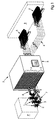
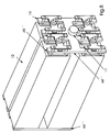
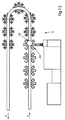
- FIG. 1 shows an overview of the transport and storage system S of the present Invention.
- this is System S for the transport and storage of stacks or bundles in one Printing press P processed, folded signatures used; however, it is not on this Application limited and can also be used for transportation and storage of others stacked or bundled products.
- the printing press P can be any conventional printing press act in which a web or sheet is printed on one or both sides.
- the web or sheets are fed to a folder 1, which may further include a cutting mechanism that cuts a web in signatures.
- the signatures are folded one or more times.
- each one of a variety of Folders 1 are supplied, with a bundle of each in each of the folders Signatures are processed with the same print image.
- the folder 1 can be any be conventional folder and is not described here.
- the one in the Folder 1 generated folded signatures are then a switchable Conveyor system 2 supplied, in which individual folded signatures to bundles or stacks summarized and fed to a loading system 3 for storage elements.
- the loading system 3 empty Storage elements 7 supplied, previously the conveyor track 4 by a suitable Storage area E for empty storage elements 7 within an automatic storage and Removal system 5 were supplied.
- the empty Positioning element 7 positioned so that it is a bundle or a stack of the switchable bundle transport path 2 can take over.
- the loading system 3 loads it empty storage element 7 with a bundle or stack which is in the storage element 7 clamped or otherwise attached.
- the storage element can then be rotated further in defined steps so that there are more bundles or stacks can record.
- the loaded one Storage element 8 After loading the storage element with bundles or stacks, the loaded one Storage element 8 by means of a suitable conveyor track 4, preferably one partially driven conveyor track, away from the loading system 3 to an automatic storage and Removal system 5 conveyed that the loaded storage elements 8 to a suitable Storage area F for loaded storage elements 8 within the storage and Removal system 5 transported, where the loaded storage elements 8 to Further processing of the signatures stored in them can be stored.
- a suitable conveyor track 4 preferably one partially driven conveyor track
- the storage elements 8 are at their storage areas F from the automatic storage and Removal system 5 localized and preferably by means of a suitable conveyor track 4 a partially driven conveyor track to the unloading system 6 for storage elements transported where the bundle or stack of folded signatures from the storage element 8 unloaded and fed to a feeder, who individually folded the signature Binder B feeds where it leads to a finished printed product, e.g. B. a book or a magazine, compiled, stapled and / or bound.
- the Binding machine B can be any conventional one that is not described in detail here Be binding machine.
- the empty storage elements 7 are by means of the conveyor track from the unloading system 6 back to the automatic storage and removal system 5 transported and in the storage areas E for empty storage elements 7 in the storage and Removal system 5 stored until they are needed again on the loading system 3.
- the entire operation of the system S is preferably via a suitable one Control device 100, e.g. B. controlled a computer.
- the control device comprises preferably a plurality of inputs (not shown) through which you provide information are fed via the various devices and systems of the overall system, e.g. B. from the printing press P, the folders 1, the bundle transport systems 2, the loading system 3, the conveyor tracks 4, the automatic storage and removal system 5, the unloading system 6 and the binding machine B.
- the entries can be made by an operator a keyboard or other input devices can be made or via sensors take place, the state of the various components and systems of the system S monitor automatically.
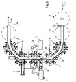
- FIG 2 is a detailed view of the portion of system S in which the blank Storage elements 7 are loaded. Empty storage elements 7 by the Dashed line are shown, are from the conveyor track 4 to the feeder side 31 of Loading system 3 transported. As explained earlier, the empty ones Storage elements 7 preferably from the conveyor track 4 from the storage areas E (Fig. 1) transported away in the automatic storage and removal system 5.
- the Loading system 3 preferably comprises a guideway 32 which is empty Storage elements 7 in a direction f (Fig. 3) in a loading position 33 where the empty storage elements 7 with bundles or stacks of 10 folded signatures become. After loading, the loaded storage elements 8 along the Guideway 32 moves to an outlet end 34 of the loading system 3 and the Transfer conveyor 4, which preferably the loaded storage elements 8 in the Storage areas F of the automatic storage and removal system 5 transported.
- the folder assigned to the loading system 3 can be any, not closer described conventional folder and is therefore not in Fig. 1-3 in detail shown.
- the folder is one in a web P printed sheet or sheet P printed in a printing machine fed, which are processed in the folder to individual folded signatures.
- the individual folded signatures are then a display 12 and the switchable transport system 2 transported where it by means of conventional Bundle devices z. B. the company Baldwin or Cieveime, which has a magazine loader can include, be bundled. Then they become a z. B. as a collective transport track trained bundle transport path 13 fed.
- On Front edge element 21 on the bundle transport system 2 forms a surface on which the folded signatures.
- the rear edge of a stack or bundle 10 lies against one (not shown) trailing edge element.
- the leading edge member 21 and that Trailing edge elements are accelerated by the bundle transport path 13, so that they Move bundle or stack 10 to the loading system 3.
- the bundles or stacks 10 are then transferred from the bundle transport path 13 into one Loading position 22 moves where the bundle or stack 10 to one located in position 33 empty storage element 7 are loaded.
- At loading position 33 there are one automatic clamping device 17 and an automatic switching device 15 arranged, both of which are preferably designed as robot arms, but also as any other type of automatic device can be designed that this Can perform functions such.
- the automatic switching device 15 rotates the one in the loading position Storage element 7 in a direction r, so that the bundle or stack 10 in the Loading position 22 on an empty clamping or gripping element 19 of the bearing element 7 meets.
- the automatic one detects Clamping device 17, the clamping or gripping element 19, which with the bundle or Stack 10 is aligned, and clamps the bundle or stack 10 in the Storage element 7 fixed.
- the bearing element 7 is then rotated further, so that a further bundle or stack 10 can be detected. This turning and Clamping process is continued until all clamping or gripping elements 19 of the in position 33 the storage element 7 are loaded with diapers or stacks 10.
- the automatic switching device 15 and the automatic clamping element 17 are then preferably withdrawn, the loaded northeastlakelement 8 is along the Guideway 32 moves further and an empty storage element 7 is in the Loading position 33 moves.
- the loaded ones Storage elements 8 from a delivery 34 of the loading system 3 to the transport track 4 pass, which the loaded storage elements 8 preferably in the storage area F transported in the automatic storage and removal system 5.
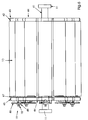
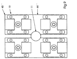
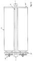
- FIG. 4-6 show detailed views of an embodiment of an inventive Storage element.
- the storage element shown in Fig. 4-6 is a loaded one Bearing element 8, all of which clamping or gripping elements 19 with bundles or Stacks 10 are loaded.
- the bearing element 8 also includes a shaft 41 opposite ends arranged bearing drums 42, 43.
- One of the bearing drums is a stationary bearing drum 42, while the other bearing drum is an adjustable one Clamp bearing drum 43 is.
- Both bearing drums 42, 43 include one at one end of the Hub 41 arranged hub 11 and frames 44 arranged on shaft 41.
- Both Frame 44 comprise clamping arms 45 protruding radially from the shaft, which are connected to a Clamping arm 45 of the opposite bearing drum are aligned.
- Opposite Clamping arms 45 thus form opposite ends of the clamping or gripping element 19 for gripping or clamping the bundle or stack 10.
- the clamping arms 45 preferably comprise adjustable ones Clamping elements 46.
- the adjustable clamping element 46 comprises an adjustable one Clamping surface or a clamping plate 47 and a threaded screw or one Threaded bolt 18, which in a threaded bore or a threaded bearing 48 on the Klemmann 45 is screwed in and connected to the adjustable clamping surface 47.
- the adjustable clamping surface 47 is directed towards the bundle or the stack 10 moved, and by rotating the head of the clamping screw or pin 18 in the other direction becomes the adjustable clamping surface or the adjustable clamping plate 47 moved away from the bundle or stack 10 so that it is released.
- the automatic clamping device 17 can be used to remove the head of the To turn the clamping screw or the clamping bolt 18 so that a in the loading position 22nd located bundle or a stack 10 can be loaded onto the storage element 7.
- the screw or bolt 18 is preferably a self-locking screw.
- the automatic clamping device 17 preferably rotates the screw or bolt 18 by a predetermined amount sufficient to hold the bundle or stack 10 and the Z. B. is measured and transmitted by means of a feedback loop.
- the hubs 11 are designed so that they can run in the guideway 32, so that the Bearing elements by means of a suitable, known drive mechanism along the Guide track 32 can be moved.
- the drive mechanism is preferred Part of the entire partially powered conveyor system 4.
- the shaft 41 is preferably via a suitable bearing, for. B. a journal bearing with the Hubs 11 connected such that the shaft 41 (and those connected to the shaft 41 Frame 44, arms 45 and clamping or gripping elements 19) with respect to the hubs 11 and Guide track 32 is rotatable.
- the automatic switching device 15 can Bring clamping or gripping elements 19 into the correct position so that they are on the previously described way can be loaded with bundles or stacks 10.
- FIG. 7 shows an alternative embodiment of the bearing element shown in FIGS. 4-6, by means of which shorter bundles or stacks 10 'can be transported and stored.
- the only difference between the embodiment shown in FIGS. 4-6 and that in FIG. 7 The embodiment shown is that in the embodiment shown in FIG. 7 the frames 44 are further displaced inward along the shaft 41 with respect to the hub 11 are to accommodate the shorter bundles or stacks 10 '. In everyone else The embodiments are identical in points.
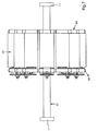
- FIG. 8 shows an alternative embodiment of a loaded storage element 8 ′′, the for transporting and storing a smaller number of bundles or stacks 10 than the embodiment shown in Figs. 4-6 is suitable.
- frames 44 '' include only four clamp arms 45 '', so only four Bundles or stacks 10 can be held while the frame 44 is the one in Figs. 4-6
- Embodiment shown include eight clamping arms 45, making eight bundles or stacks 10 can be detected.
- the embodiments are in all other respects identical, the embodiment shown in FIG. 8 also being similar to that in FIG. 7 shown variant can be designed for shorter bundles or stacks.
- the automatic storage and removal system 5 can be based on known ones Storage elements can be constructed, which for the storage of rolled or on pallets stored products are used, such as. B. the automatic Product handling systems from Activ Systems or Murata Automated Systems Inc. The details of such systems are known, but include these systems usually a frame that defines a number of storage areas.
- a Control device such. B. The control device 100 monitors the supply and removal loaded storage elements 8 and empty storage elements 7 in the automatic storage and removal system 5. This is preferably done by attaching achieved by barcode labels on the storage elements, which on the feed and Tapping points of the storage and tapping system 5 arranged bar code readers to be read.
- control device By monitoring the position of each bearing element the control device can be coupled to the control device by means of bar code readers determine on which of the folders 1 a storage element 8 was loaded, and can thus determine in which storage area in the automatic storage and Removal system 5 a loaded storage element 8 is to be stored and to which The loading and unloading device 6 a loaded storage element 8 can be transported should. In this way it is ensured that folded and printed in a certain way Signatures are transported to the correct loading and unloading device 6 from which they are fed to the binding machine B so that the folded signatures are in the correct Order is gathered, stapled and bound.
- Both the conveyor tracks 4 and the transport tracks, not shown, inside the automatic storage and removal system 5 are preferably as a partially powered Conveyor track system trained, as z. B. under the name RAPID FLOW TM from the Rapid Industries, Inc. is offered in Louisville, Kentucky.
- This Transport systems include guideways that are connected to the hubs 11 at the Storage elements can interact, and the optional free movement of the Allow hubs 11 or a slider, chain or other device May include, which moves the hubs 11 along the guideways.
- the switches are preferred controlled by the control device 100 to ensure that a particular one Bearing element along the correct guideway to the correct one Barcode corresponding storage area or to the correct processing station is transported.
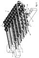
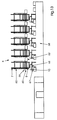
- FIG. 11-13 are detailed views of the loading and unloading system 6.
- Loaded Storage elements 8 are removed from the automatic storage and removal system 5 along the transport tracks 4 into a guide track of a plurality of guide tracks 60 emotional.
- the guideway 60 into which a loaded bearing element 8 is moved becomes from the control device 100 on the basis of that applied to the bearing element Determines bar code information that is stored in the control device 100 and that Specify in particular on which folder 1 the corresponding bearing element 8 was loaded.
- the docking and unloading system 6 can be used if necessary folded signatures are fed in the correct order so that the signatures fed to the binding machine, collated, stapled and finished Printed product, e.g. B. a book or magazine.
- a loaded storage element 8 is up to along a certain guideway 60 an unloading position 65 moves.
- Each of the guideways is a continuation of the partially driven transport system, which the conveyor track 4 and the conveyor track in Inside of the automatic storage and removal system 5 includes.
- a stepper motor and a gear box 62 are arranged, by means of which the loaded Storage element 8 is rotated in defined steps, so that in the Storage element 8 stored bundle or stack 10 can be unloaded one after the other can.
- a release device 66 also arranged at the unloading position 65, e.g. B. a pneumatically or electrically operated, retractable clamping device turns the Screw or the bolt 18 in one direction and thus loosens a bundle or a stack 10 from the storage element 8.
- the loosened bundles or stacks 10 are, preferably transferred to unloading devices 61 by means of a magazine loader, e.g. B. at below the Unloading position 65 arranged switchable conveyor tracks, which the folded signatures feed the bundle or stack 10 to a binding machine feeder 67.
- the investor 67 feeds the binding machine B 68 individual folded signatures via a transport system then gathered in the binding machine B, stapled and finished Printed product, e.g. B. a book or magazine.
- the Storage element along the conveyor track 60 to the transport track 4 and back to the automatic storage and removal system 5 transported so that it can be used again can be.
- the storage elements can be monitored by the Control device 100 permanently circulate automatically in the system 5, so that each loading and unloading system 6 has a constant supply of bundles or stacks 10 he follows.
- a control device 100 by bar codes on each of the Bearing elements 7, 8 and by the controlled, partially driven conveyor system within the entire system S, the entire process of manufacturing, transport, Storage, feeding and binding of the signatures automatically and without human intervention respectively. Accordingly, with this system with accurate control of the whole Printing and binding process labor can be saved.
Landscapes
- Engineering & Computer Science (AREA)
- Mechanical Engineering (AREA)
- Pile Receivers (AREA)
- Collation Of Sheets And Webs (AREA)
- Feeding Of Articles By Means Other Than Belts Or Rollers (AREA)
Abstract
Description
- Fig. 1
- eine systematische, perspektivische Übersicht des erfindungsgemäßen Systems;
- Fig. 2
- eine perspektivische Detailansicht einer Falzapparatauslage, eines schaltbaren Transportsystems für Bündel oder Stapel, einer Beladevorrichtung für Lagerungselemente und einer teilangetriebenen Förderbahn, wie sie an der Auslage der Druckmaschine des Systems von Fig. 1 eingesetzt wird;
- Fig. 3
- eine Seitenansicht der in Fig. 2 gezeigten Komponenten;
- Fig. 4
- eine perspektivische Darstellung einer ersten Ausführungsform eines Lagerungselements gemäß der vorliegenden Erfindung;
- Fig. 5
- eine Vorderansicht des in Fig. 4 gezeigten Lagerungselements;
- Fig. 6
- eine Seitenansicht des in Fig. 4 gezeigten Lagerungselements;
- Fig. 7
- eine Seitenansicht einer alternativen Ausführungsform des in Fig. 4 gezeigten Lagerungselements;
- Fig. 8
- eine perspektivische Darstellung einer weiteren Ausführungsform eines Lagerungselements gemäß der vorliegenden Erfindung;
- Fig. 9
- eine Vorderansicht des in Fig. 8 gezeigten Lagerungselements;
- Fig. 10
- eine Seitenansicht des in Fig. 8 gezeigten Lagerungselements;
- Fig. 11
- eine perspektivische Teilansicht des Anleger- und Entladesystems einer Bindemaschine gemäß der vorliegenden Erfindung;
- Fig. 12
- eine Seitenansicht des in Fig. 11 gezeigten Systems;
- Fig. 13
- eine Vorderansicht des in Fig. 11 gezeigten Systems.
- 1
- Falzapparate
- 2
- schaltbares Fördersystem
- 3
- Beladevorrichtung
- 4
- Förderbahn
- 5
- automatisches Lager- und Entnahmesystem
- 6
- Entladesystem
- 7
- leere Lagerungselemente
- 8
- beladene Lagerungselemente
- 10
- Bündel/Stapel
- 11
- Nabe
- 12
- Auslage der Falzapparate
- 13
- Bündel-Transportbahn
- 15
- automatische Schaltvorrichtung
- 17
- automatische Klemmvorrichtung
- 18
- Gewindeschraube/-bolzen
- 19
- Klemm- oder Greifelement
- 21
- Vorderkantenelement
- 22
- Beladeposition
- 31
- Anlegerseite der Beladevorrichtung
- 32
- Führungsbahn
- 33
- Beladeposition
- 34
- Austrittsende des Beladesystems
- 41
- Welle
- 42
- ortsfeste Lagertrommel
- 43
- verstellbare Klemmlagertrommel
- 44
- Rahmen
- 44''
- Rahmen
- 45
- Klemmarme
- 45''
- Klemmarme
- 46
- verstellbares Klemmelement
- 47
- Klemmfläche
- 60
- Führungsbahn
- 61
- Entladevorrichtung
- 62
- Getriebekasten
- 65
- Entladeposition
- 66
- Lösevorrichtung
- 67
- Bindemaschinen-Anleger
- 68
- Transportsystem
- 100
- Steuervorrichtung
- B
- Bindemaschine
- E
- Lagerbereich für leere Lagerungselemente
- F
- Lagerbereich für beladene Lagerungselemente
- P
- Druckmaschine
- S
- Transport- und Lagersystem
- f
- Drehrichtung
- r
- Drehrichtung
Claims (5)
- Lagerelement (7, 8) zum Transport und zur Entnahme von Produkten mit einer Welle (41), an deren beiden Enden jeweils eine Nabe (11) drehbar angeordnet ist, mit einer Vielzahl von an der Welle (41) angeordneten Rahmen (45, 46) und mit mindestens einer an mindestens einem der Rahmen (45, 46) angeordneten Klemmvorrichtung (19).
- Vorrichtung zum Transportieren und Lagern von Produkten mit einer Förderbahn (4), die eine Vielzahl von Führungsbahnen (60) umfasst,
dadurch gekennzeichnet,dass die Vorrichtung zum Transportieren und Lagern wenigstens ein Lagerungselement gemäß Anspruch 1 aufweist, wobei jede der Naben (11) in einer der Führungsbahnen (60) angeordnet ist;dass weiterhin eine Beladevorrichtung (3) vorgesehen ist, welche ein Produkt in der mindestens einen Klemmvorrichtung (19) festklemmt unddass eine Entladevorrichtung (6) vorgesehen ist, welche die mindestens eine Klemmvorrichtung (19) von dem Produkt (10) löst. - Vorrichtung zum Transportieren und Lagern gestapelter Signaturen nach Anspruch 2,
dadurch gekennzeichnet,dass die Beladestation (3) so ausgestaltet ist, dass sie eine Vielzahl von Produkten stapeln und die Klemmvorrichtung (19) eine Vielzahl von Produkten festklemmen kann und dass die Enfladevorrichtung (6) so ausgeführt ist, dass sie die Vielzahl von Signaturen wieder vereinzeln kann. - Verfahren zum Transportieren und Lagern von Produkten,
gekennzeichnet durchdie folgenden Schritte:Bereitstellen eines Lagerungselements (7, 8) mit mindestens einer Klemmvorrichtung (19);Transportieren des Lagerungselements (7, 8) auf einer Förderbahn (4) zu einer Beladestation (3);Beladen des Lagerungselements (7, 8) mit mindestens einem Produkt;Festklemmen des mindestens einen Produkts mit der mindestens einen Klemmvorrichtung (19);Transportieren des Lagerungselements (7, 8) auf der Förderbahn (4) zu einem Lagerbereich (F);Lagern des Lagerungselements (7, 8) in dem Lagerbereich (F);Transportieren des Lagerungselements (7, 8) auf einer Förderbahn zu einer Entladestation (6);Lösen des mindestens einen Produkts mittels der mindestens einen Klemmvorrichtung (19) undEntladen des mindestens einen Produkts von dem Lagerungselement (7, 8). - Verfahren zum Transportieren und Lagern von Signaturen,
gekennzeichnet durchdie folgenden Schritte:Bereitstellen eines Lagerungselements (7, 8) mit mindestens einer Klemmvorrichtung (19);Transportieren des Lagerungselements (7, 8) auf einer Förderbahn (4) zu einer Beladestation (3);Stapeln einer Vielzahl von Signaturen;Beladen des Lagerungselements (7, 8) mit gestapelten Signaturen;Festklemmen der gestapelten Signaturen mit der mindestens einen Klemmvorrichtung (19);Transportieren des Lagerungselements (7, 8) auf der Förderbahn (4) zu einem Lagerbereich (F);Lagern des Lagerungselements (7, 8) in dem Lagerbereich (F);Transportieren des Lagerungselements (7, 8) auf einer Förderbahn (4) zu einer Entladestation (6);Lösen der gestapelten Signaturen mittels der mindestens einen Klemmvorrichtung (19);Entladen der gestapelten Signaturen von dem Lagerungselement (7, 8) undVereinzeln der gestapelten Signaturen.
Applications Claiming Priority (2)
| Application Number | Priority Date | Filing Date | Title |
|---|---|---|---|
| US28209399A | 1999-03-30 | 1999-03-30 | |
| US282093 | 1999-03-30 |
Publications (2)
| Publication Number | Publication Date |
|---|---|
| EP1041018A2 true EP1041018A2 (de) | 2000-10-04 |
| EP1041018A3 EP1041018A3 (de) | 2002-05-22 |
Family
ID=23080081
Family Applications (1)
| Application Number | Title | Priority Date | Filing Date |
|---|---|---|---|
| EP00104493A Withdrawn EP1041018A3 (de) | 1999-03-30 | 2000-03-09 | Vorrichtung und Verfahren zum Transportieren und Lagern von Produkten |
Country Status (3)
| Country | Link |
|---|---|
| EP (1) | EP1041018A3 (de) |
| JP (1) | JP2000318919A (de) |
| DE (1) | DE10011435A1 (de) |
Family Cites Families (4)
| Publication number | Priority date | Publication date | Assignee | Title |
|---|---|---|---|---|
| CH668411A5 (de) * | 1985-12-20 | 1988-12-30 | Ferag Ag | Vorrichtung zum speichern von in schuppenformation anfallenden druckprodukten. |
| DE3738974C1 (de) * | 1987-11-17 | 1989-06-01 | Kleinewefers Gmbh | Walzenmagazin fuer Walzen von Superkalandern |
| US5540422A (en) * | 1994-10-24 | 1996-07-30 | Baldwin Technology Corporation | Stacker-bundler transfer apparatus |
| ATE222212T1 (de) * | 1996-07-19 | 2002-08-15 | Ferag Ag | Vorrichtung zum zubringen von druckereierzeugnissen zu verarbeitungsstationen |
-
2000
- 2000-03-09 DE DE2000111435 patent/DE10011435A1/de not_active Withdrawn
- 2000-03-09 EP EP00104493A patent/EP1041018A3/de not_active Withdrawn
- 2000-03-30 JP JP2000093432A patent/JP2000318919A/ja active Pending
Also Published As
| Publication number | Publication date |
|---|---|
| EP1041018A3 (de) | 2002-05-22 |
| DE10011435A1 (de) | 2000-10-05 |
| JP2000318919A (ja) | 2000-11-21 |
Similar Documents
| Publication | Publication Date | Title |
|---|---|---|
| DE69815467T2 (de) | Verfahren zum Sortieren und Zuführen von gedruckten Dokumenten nach einer Endbearbeitungsmaschine | |
| DE102006032204B3 (de) | Verfahren zur Bereitstellung mindestens einer Druckform an ihrem Montageort auf einem Formzylinder einer Rotationsdruckmaschine | |
| DE60300126T2 (de) | Verfahren und Vorrichtung zum automatischen Verpacken von Gegenständen | |
| EP3285978B1 (de) | Einrichtung für die durchführung von schneidoperationen offener formatkanten eines druckproduktes | |
| DE3203506A1 (de) | Vorrichtung zum einfuehren von blattpaketen in eine bearbeitungsmaschine | |
| EP3482892B1 (de) | Verfahren für die durchführung von schneidoperationen offener formatkanten eines druckproduktes | |
| EP0470362B1 (de) | Bogen verarbeitende Maschine und damit zusammenarbeitende Transporteinrichtung für Bogenstapel | |
| EP1156003B1 (de) | Vorrichtung zum Zusammentragen flacher Druckprodukte | |
| DE19515705C2 (de) | Einrichtung zur Bearbeitung von Blattstapeln | |
| EP1939008A2 (de) | Sammelhefter mit variabler Kettenteilung | |
| DE69909446T2 (de) | Verfahren und Vorrichtung zum Markieren von Papier-, Wellpappe- und Cellulosebahnrollen | |
| EP1995195A2 (de) | Vorrichtung zum Zuführen von Bogen an eine Verarbeitungsmaschine und Verfahren zur Beschickung der Vorrichtung | |
| EP0659586A1 (de) | Verfahren zur Beschickung von zu Druckprodukten gesammelten, mehrblättrigen Druckbogen mit Beilagen | |
| DE202008011786U1 (de) | Rollendruckmaschine | |
| DE69710016T2 (de) | Vorrichtung zum Sammeln und zur gerichteten Orientierung von Bögen | |
| DE102009004640B4 (de) | Vorrichtung und Verfahren zum Beigeben von Belegen in Kommissionieranlagen | |
| DE69113964T2 (de) | Bogenzuführvorrichtung. | |
| EP3208098B1 (de) | Deckenanleger und verfahren zum bereitstellen von buchdecken | |
| EP1041018A2 (de) | Vorrichtung und Verfahren zum Transportieren und Lagern von Produkten | |
| EP2181953B1 (de) | Einrichtung zur Zuführung von Druckbogen für die Herstellung von Buchblocks, Büchern oder dgl. Druckerzeugnissen | |
| EP1302423B1 (de) | Modul zur temporären Lagerung von flachen Druckprodukten | |
| EP3597429B1 (de) | Verfahren zur herstellung eines druckereiprodukts mit mehr als vier bedruckten seiten | |
| DE10220550A1 (de) | Verfahren und Vorrichtung zur Weiterverarbeitung von Druckzwischenprodukten | |
| DE69711260T2 (de) | Mit einer Heftvorrichtung versehenes Blattsortiergerät | |
| EP2338683B1 (de) | Plattenrevolver |
Legal Events
| Date | Code | Title | Description |
|---|---|---|---|
| PUAI | Public reference made under article 153(3) epc to a published international application that has entered the european phase |
Free format text: ORIGINAL CODE: 0009012 |
|
| AK | Designated contracting states |
Kind code of ref document: A2 Designated state(s): AT BE CH CY DE DK ES FI FR GB GR IE IT LI LU MC NL PT SE |
|
| AX | Request for extension of the european patent |
Free format text: AL;LT;LV;MK;RO;SI |
|
| PUAL | Search report despatched |
Free format text: ORIGINAL CODE: 0009013 |
|
| AX | Request for extension of the european patent |
Free format text: AL;LT;LV;MK;RO;SI |
|
| 17P | Request for examination filed |
Effective date: 20020411 |
|
| 17Q | First examination report despatched |
Effective date: 20021015 |
|
| AKX | Designation fees paid |
Designated state(s): AT BE CH CY DE DK ES FI FR GB GR IE IT LI LU MC NL PT SE |
|
| GRAH | Despatch of communication of intention to grant a patent |
Free format text: ORIGINAL CODE: EPIDOS IGRA |
|
| STAA | Information on the status of an ep patent application or granted ep patent |
Free format text: STATUS: THE APPLICATION IS DEEMED TO BE WITHDRAWN |
|
| 18D | Application deemed to be withdrawn |
Effective date: 20031017 |