EP1040986B1 - Entnahmehilfe für ein Reserverad - Google Patents
Entnahmehilfe für ein Reserverad Download PDFInfo
- Publication number
- EP1040986B1 EP1040986B1 EP00104205A EP00104205A EP1040986B1 EP 1040986 B1 EP1040986 B1 EP 1040986B1 EP 00104205 A EP00104205 A EP 00104205A EP 00104205 A EP00104205 A EP 00104205A EP 1040986 B1 EP1040986 B1 EP 1040986B1
- Authority
- EP
- European Patent Office
- Prior art keywords
- spare wheel
- spare
- removal aid
- aid according
- belt
- Prior art date
- Legal status (The legal status is an assumption and is not a legal conclusion. Google has not performed a legal analysis and makes no representation as to the accuracy of the status listed.)
- Expired - Lifetime
Links
Images


Classifications
-
- B—PERFORMING OPERATIONS; TRANSPORTING
- B62—LAND VEHICLES FOR TRAVELLING OTHERWISE THAN ON RAILS
- B62D—MOTOR VEHICLES; TRAILERS
- B62D43/00—Spare wheel stowing, holding, or mounting arrangements
- B62D43/06—Spare wheel stowing, holding, or mounting arrangements within the vehicle body
- B62D43/10—Spare wheel stowing, holding, or mounting arrangements within the vehicle body and arranged substantially horizontally
Definitions
- the present invention relates to a removal aid for a spare wheel Motor vehicle.
- DE-C-40 40 950 is a generic removal aid for a spare wheel of a motor vehicle known.
- This known removal aid includes a Band, which at one end on a body section, namely the spare wheel well, is attached. The band extends from there under the spare wheel and beyond that. The other end can be live on another Body section, namely the loading edge of the trunk, attached become.
- the spare wheel can be raised by means of the drawstring and after tensioning the tape over that formed by the tape pulled out and / or introduced inclined plane.
- this known removal aid does provide a certain reduction in force when Ready to install and remove the spare wheel, but there is a significant risk that the spare wheel laterally from the inclined plane formed by the tape could slide down. Especially with heavy and bulky spare wheels there is therefore the possibility of damage and / or contamination of the trunk.
- a generic Removal aid for a spare wheel of a motor vehicle in such a way, that the above disadvantages are eliminated.
- a generic Removal aid for a spare wheel trained in such a way be that the spare wheel is removed from the spare wheel well and can be inserted.
- this task is performed by a removal aid for a spare wheel of a motor vehicle with the features of claim 1 solved.
- preferred Embodiments are listed in the dependent claims.
- a removal aid for a spare wheel is used Motor vehicle specified with at least one band, which on a End is fixed on a body section, from there under the spare wheel and extends beyond this and which at the other end with another body section can be clamped, the removal aid is characterized by a spare wheel receiving device that is slidable is formed with respect to the band.
- the invention a kind of carriage provided on the belt, by means of which the spare wheel can be slid on the belt in the tensioned state. Accordingly can make a precise movement when inserting and removing of the spare wheel.
- the risk of the spare wheel sliding sideways can by the slidably trained spare wheel receiving device be practically excluded.
- the spare wheel receiving device is advantageously essentially in the shape of a half-shell.
- This half shell can e.g. as a Plastic injection molded part or also made of metal, e.g. adapted to the Geometry of the spare wheel well and / or the spare wheel to be supported.
- the spare wheel receiving device comprises advantageously at least one rail-shaped Strip.
- the spare wheel receiving device comprises Spare wheel fixing means so that the spare wheel is related can be fixed on the spare wheel receiving device, e.g. by the spare wheel can be screwed to the spare wheel holder.
- the band is advantageously at at least two points on the spare wheel receiving device guided.
- the strap can be buckled on two trained sections with respect to the spare wheel receiving device be slidably guided.
- the band becomes half-shell-shaped on the one hand on a radial section trained spare wheel receiving device and on the other hand on one distal end of the rail-shaped bar.
- the belt can be gripped assigned to e.g. is sewn to it.
- the spare wheel can be easily lifted with minimal effort become.
- the belt is a tensioning device assigned to interact with one on the other body section trained recess serves.
- the recess on the other body section keyhole-shaped for easy engagement and disengagement to ensure the band with the other body section.
- the other body section is advantageously a movable body section, e.g. the lower part of a two-part tailgate, so that the desired Tensioning the belt by moving the movable body section can be achieved.
- the straps be substantially tensioned run parallel, in particular essentially in the direction of the vehicle.
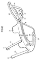
- the removal aid for a spare wheel comprises two bands 10, 20, which in the position shown run loosely below a spare wheel, not shown.
- the two bands 10, 20 are fastened at one end 11, 21 with a body section, for example a cross member, medium screws or other suitable means.
- the bands 10, 20 extend from these ends 11, 21 towards the spare wheel, not shown, below and beyond it.
- a spare wheel receiving device 30 is provided in the embodiment shown, which can support the spare wheel from below essentially in the form of a half-shell.
- the spare wheel receiving device of the embodiment shown here is designed as a plastic injection molded part and is designed at two points 38, 39 and 36, 37 for interaction with a band 10, 20 in each case.
- the interaction taking place at points 36, 37, 38, 39 should enable the spare wheel receiving device 30 to slide along the bands 10, 20.
- the engagement between the bands 10, 20 and the spare wheel receiving device 30 provided at points 36, 37, 38, 39 is similar to a buckle, ie the bands 10, 20 slide in eyelets on the respective ones Points 36, 37, 38, 39 are performed.
- the spare wheel receiver is essentially formed in the shape of a half-shell, the spare wheel receiving device the embodiment shown here also two rail-shaped Strips 32, 34 includes so that the respective points 36, 37 and 38, 39 can be more spaced apart.
- the spare wheel receptacle 30 partially comprises trained stop surfaces 31, which serve to fix the spare wheel.
- the belts 10, 20 are behind the spare wheel a handle 40 connected by means of which the straps or straps 10, 20 tensioned can be.
- a tensioning device 42 is assigned to the handle 40, which has a trained for this purpose Opening in a body section can interact.
- the removal aid for a spare wheel shown in FIG. 1 is in one shown middle position, in which the bands 10, 20 by means of the handle 40 were slightly cocked. By tensioning the tapes 10, 20 was in the position shown the spare wheel receptacle 30 at the front end slightly raised.
- the spare wheel receiving device 30 is raised substantially uniformly while it is particularly preferred that some friction at points 36, 37, 38, 39 between the spare wheel receiving device 30 and the bands 10, 20 is present, so that a sliding movement when the bands 10, 20 are acted upon can only take place after lifting.
- various settings are available in this regard.
- FIGS. 1 and 2 the embodiment shown in FIGS. 1 and 2 is shown in FIG End position shown, the straps 10, 20 are completely tensioned and in essentially run in one plane.
- the bands 10, 20 thus form an oblique one Level, on which the sliding spare wheel mounting device is interposed 30 the spare wheel can be moved back and forth and thus precise position and with little effort from the trunk can be removed or inserted into this.
- the two tapes 10, 20 are provided at a certain distance from each other and essentially extending in the direction of the vehicle, there is no risk that the spare wheel tilted and could slide off the inclined plane.
- the fixing means 31, in the embodiment shown designed as simple stops a movement of the spare wheel with respect to the spare wheel receiving device 30 inhibited.
- the tensioning device 42 is formed in such a form that e.g. with the bottom section a two-part tailgate can interact, so that with light train application the bands 10, 20 in Fig. 2 an engagement between the device 42 and the tailgate can be achieved.
- a subsequent opening of the lower part of the vehicle tailgate becomes the position shown in FIG. 3 achieved what automatically tensions when opening the lower part of the tailgate the straps and thus the removal of the spare wheel.
Landscapes
- Engineering & Computer Science (AREA)
- Chemical & Material Sciences (AREA)
- Combustion & Propulsion (AREA)
- Transportation (AREA)
- Mechanical Engineering (AREA)
- Emergency Lowering Means (AREA)
- Vehicle Cleaning, Maintenance, Repair, Refitting, And Outriggers (AREA)
- Handcart (AREA)
Description
Die Reserverad-Aufnahmeeinrichtung der hier dargestellten Ausführungsform ist als ein Kunststoff-Spritzgußteil ausgebildet und ist an jeweils zwei Punkten 38, 39 bzw. 36, 37 zur Wechselwirkung mit jeweils einem Band 10, 20 ausgebildet. Die an den Punkten 36, 37, 38, 39 stattfindende Wechselwirkung sollte ein Gleiten der Reserverad-Aufnahmeeinrichtung 30 entlang den Bändern 10, 20 ermöglichen. In der hier dargestellten Ausführungsform ist der an den Punkten 36, 37, 38, 39 vorgesehene Eingriff zwischen den Bändern 10, 20 und der Reserverad-Aufnahmeeinrichtung 30 ähnlich zu einer Schnalle ausgebildet, d.h. daß die Bänder 10, 20 gleitend in Ösen an den jeweiligen Punkten 36, 37, 38, 39 geführt sind.
Claims (10)
- Entnahmehilfe für ein Reserverad eines Kraftfahrzeuges mit zumindest einem Band (10, 20), welches an einem Ende (11, 21) an einem Karosserieabschnitt festgelegt ist, sich von dort unter dem Reserverad und über dieses hinaus erstreckt und welches an dem anderen Ende (12, 22) mit einem anderen Karosserieabschnitt verspannbar ist, gekennzeichnet durch eine Reserverad-Aufnahmeeinrichtung (30), die gleitfähig bezüglich dem Band (10, 20) ausgebildet ist.
- Entnahmehilfe nach Anspruch 1, dadurch gekennzeichnet, daß die Reserverad-Aufnahmeeinrichtung (30) im wesentlichen in der Form einer Halbschale ausgebildet ist.
- Entnahmehilfe nach Anspruch 1 oder 2, dadurch gekennzeichnet, daß die Reserverad-Aufnahmeeinrichtung zumindest eine schienenförmige Leiste (32, 34) umfaßt.
- Entnahmehilfe nach einem der vorangegangenen Ansprüche, dadurch gekennzeichnet, daß die Reserverad-Aufnahmeeinrichtung (30) Reserverad-Fixiermittel (31) umfaßt.
- Entnahmehilfe nach einem der vorangegangenen Ansprüche, dadurch gekennzeichnet, daß das Band an zumindest zwei Punkten (36, 37; 38, 39) an der Reserverad-Aufnahmeeinrichtung (30) geführt ist.
- Entnahmehilfe nach einem der vorangegangenen Ansprüche, dadurch gekennzeichnet, daß dem Band ein Griff (40) zugeordnet ist, welcher insbesondere mit dem Band vernäht ist.
- Entnahmehilfe nach einem der vorangegangenen Ansprüche, dadurch gekennzeichnet, daß dem Band (10, 20) eine Verspanneinrichtung (42) zugeordnet ist, die zur Wechselwirkung mit einer an dem anderen Karosserieabschnitt ausgebildeten, insbesondere schlüssellochförmigen Aussparung dient.
- Entnahmehilfe nach einem der vorangegangenen Ansprüche, dadurch gekennzeichnet, daß der andere Karosserieabschnitt ein beweglicher Karosserieabschnitt ist.
- Entnahmehilfe nach einem der vorangegangenen Ansprüche, dadurch gekennzeichnet, daß zumindest zwei Bänder (10, 20) vorgesehen sind.
- Entnahmehilfe nach Anspruch 9, dadurch gekennzeichnet, daß sich die Bänder (10, 20) im verspannten Zustand im wesentlichen parallel, insbesondere im wesentlichen in Fahrzeugrichtung erstrecken.
Applications Claiming Priority (2)
| Application Number | Priority Date | Filing Date | Title |
|---|---|---|---|
| DE19914537 | 1999-03-31 | ||
| DE19914537A DE19914537A1 (de) | 1999-03-31 | 1999-03-31 | Entnahmehilfe für ein Reserverad |
Publications (3)
| Publication Number | Publication Date |
|---|---|
| EP1040986A2 EP1040986A2 (de) | 2000-10-04 |
| EP1040986A3 EP1040986A3 (de) | 2003-04-02 |
| EP1040986B1 true EP1040986B1 (de) | 2004-06-23 |
Family
ID=7903024
Family Applications (1)
| Application Number | Title | Priority Date | Filing Date |
|---|---|---|---|
| EP00104205A Expired - Lifetime EP1040986B1 (de) | 1999-03-31 | 2000-03-01 | Entnahmehilfe für ein Reserverad |
Country Status (3)
| Country | Link |
|---|---|
| US (1) | US6279793B1 (de) |
| EP (1) | EP1040986B1 (de) |
| DE (2) | DE19914537A1 (de) |
Families Citing this family (7)
| Publication number | Priority date | Publication date | Assignee | Title |
|---|---|---|---|---|
| US6648577B2 (en) * | 2001-06-12 | 2003-11-18 | Kelly M. Obriot | Vehicle spare tire container |
| US7410081B2 (en) * | 2003-09-16 | 2008-08-12 | Honda Motor Company, Ltd. | Support structure for a spare tire on a vehicle |
| US7954679B2 (en) * | 2004-07-20 | 2011-06-07 | Honda Motor Company, Ltd. | Retention system for a spare tire |
| ITBO20100268A1 (it) * | 2010-04-30 | 2011-10-31 | Ferrari Spa | Veicolo provvisto di ruota di scorta |
| US20160121942A1 (en) * | 2014-10-29 | 2016-05-05 | Ford Global Technologies, Llc | Spare tire assembly for a motor vehicle |
| FR3037307B1 (fr) * | 2015-06-09 | 2018-08-31 | Renault S.A.S | Dispositif d'extraction d'une roue hors d'un logement de rangement et vehicule equipe d'un tel dispositif |
| US20190002040A1 (en) * | 2017-06-28 | 2019-01-03 | GM Global Technology Operations LLC | Spare tire removal feature, system, and method |
Family Cites Families (13)
| Publication number | Priority date | Publication date | Assignee | Title |
|---|---|---|---|---|
| US1813094A (en) * | 1928-09-10 | 1931-07-07 | Joseph J Appel | Tire carrier |
| US1913835A (en) * | 1931-06-15 | 1933-06-13 | Ind Patents Corp | Tire carrier |
| US3712586A (en) * | 1971-09-27 | 1973-01-23 | Ford Motor Co | Spare tire extractor assist device |
| US3782568A (en) * | 1972-09-14 | 1974-01-01 | G Alexander | Spare tire carrier |
| US3940041A (en) * | 1973-05-14 | 1976-02-24 | Bott John Anthony | Spare tire extraction device |
| US4087032A (en) * | 1977-05-12 | 1978-05-02 | General Motors Corporation | Spare tire stowage assembly |
| GB2155421A (en) * | 1984-03-10 | 1985-09-25 | Austin Rover Group | Apparatus for assisting in the removal of a spare wheel from its housing |
| US4676415A (en) * | 1985-12-16 | 1987-06-30 | Kennedy Albert B | Slide-out bumper and tire carrier |
| US4805817A (en) * | 1986-10-17 | 1989-02-21 | Helterbrand David L | Locking bar for use with a spare tire carrier |
| DE4040950C1 (en) | 1990-12-20 | 1992-04-02 | Audi Ag, 8070 Ingolstadt, De | Removal of spare wheel from car boot - involves belt under wheel with handle lying on top |
| US5238358A (en) * | 1992-05-26 | 1993-08-24 | Higgins Betty W | Vehicle spare tire storage and retrieval apparatus |
| FR2731977A1 (fr) * | 1995-03-23 | 1996-09-27 | Peugeot | Dispositif de manipulation d'une roue de secours |
| US5803324A (en) * | 1997-05-07 | 1998-09-08 | Silberman; Scott A. | Lightweight stowable tire carrier for automotive vehicle and method of use |
-
1999
- 1999-03-31 DE DE19914537A patent/DE19914537A1/de not_active Withdrawn
-
2000
- 2000-03-01 DE DE50006861T patent/DE50006861D1/de not_active Expired - Lifetime
- 2000-03-01 EP EP00104205A patent/EP1040986B1/de not_active Expired - Lifetime
- 2000-03-16 US US09/526,741 patent/US6279793B1/en not_active Expired - Lifetime
Also Published As
| Publication number | Publication date |
|---|---|
| EP1040986A2 (de) | 2000-10-04 |
| DE19914537A1 (de) | 2000-10-05 |
| EP1040986A3 (de) | 2003-04-02 |
| DE50006861D1 (de) | 2004-07-29 |
| US6279793B1 (en) | 2001-08-28 |
Similar Documents
| Publication | Publication Date | Title |
|---|---|---|
| DE60013385T2 (de) | Fahrradträger angepasst zur Montage im Inneren eines Kraftfahrzeuges | |
| DE10158005B4 (de) | Bügelzwinge | |
| DE69721599T2 (de) | Schnappriegel | |
| DE69606758T2 (de) | Lastkraftwagen-Planenabdeckungs-Vorrichtung | |
| DE60132040T2 (de) | Schuhbindung für Snowboard oder Rollbrett | |
| DE10339449B4 (de) | Fahrzeuglastenträger für ein Kraftfahrzeug | |
| EP1426548A2 (de) | Rollosystem, insbesondere für ein Kraftfahrzeug | |
| DE102017203232A1 (de) | Zweirad-fixiervorrichtung für pickup-kleinlastwagen | |
| DE69406150T2 (de) | Dachgepäckträger, Skiträger oder ähnliches für Kraftfahrzeuge mit Dachreling | |
| EP1040986A2 (de) | Entnahmehilfe für ein Reserverad | |
| DE3432669A1 (de) | Sicherheitsgurtsystem, insbesondere in einem kraftfahrzeug | |
| DE3939664C2 (de) | Einsteckzunge für Sicherheitsgurte | |
| DE60108058T2 (de) | Einziehbare Leiter | |
| DE9412066U1 (de) | Vorrichtung zum sicheren Ablegen von Gegenständen auf Kraftfahrzeugsitzen | |
| EP2229539A2 (de) | Montagehilfe und montageverfahren | |
| DE102013105472B4 (de) | Laderaumabdeckung | |
| DE69802872T2 (de) | Schlauchklemme mit verschlusshebel | |
| WO1982003827A1 (fr) | Dispositif de support | |
| DE19839824A1 (de) | Seitenplanenaufhängung an Verdecken für Nutzfahrzeuge | |
| DE68907773T2 (de) | Dachtraeger fuer fahrzeuge zum befestigen ohne externe stuetzen. | |
| DE69305573T2 (de) | Skihalter, insbesondere für Geländefahrzeuge, geschlossene Lastkraftwagen und dergleichen | |
| DE10059787A1 (de) | Abdeckplatte für eine im Kofferraumboden eines Kraftfahrzeug-Kofferraums ausgebildete wenigstens eine Lademulde | |
| DE69314862T2 (de) | Verriegelungsvorrichtung für motorrad | |
| DE2650077A1 (de) | Vorrichtung zum zusammenhalten und transportieren von skiern | |
| DE19642551B4 (de) | Arretiervorrichtung für ein Trittbrett und mit einer Arretiervorrichtung versehenes Trittbrett |
Legal Events
| Date | Code | Title | Description |
|---|---|---|---|
| PUAI | Public reference made under article 153(3) epc to a published international application that has entered the european phase |
Free format text: ORIGINAL CODE: 0009012 |
|
| AK | Designated contracting states |
Kind code of ref document: A2 Designated state(s): AT BE CH CY DE DK ES FI FR GB GR IE IT LI LU MC NL PT SE |
|
| AX | Request for extension of the european patent |
Free format text: AL;LT;LV;MK;RO;SI |
|
| PUAL | Search report despatched |
Free format text: ORIGINAL CODE: 0009013 |
|
| AK | Designated contracting states |
Kind code of ref document: A3 Designated state(s): AT BE CH CY DE DK ES FI FR GB GR IE IT LI LU MC NL PT SE |
|
| AX | Request for extension of the european patent |
Extension state: AL LT LV MK RO SI |
|
| RIC1 | Information provided on ipc code assigned before grant |
Ipc: 7B 62D 43/10 B Ipc: 7B 62D 43/04 A |
|
| 17P | Request for examination filed |
Effective date: 20030226 |
|
| GRAP | Despatch of communication of intention to grant a patent |
Free format text: ORIGINAL CODE: EPIDOSNIGR1 |
|
| AKX | Designation fees paid |
Designated state(s): DE FR GB |
|
| GRAS | Grant fee paid |
Free format text: ORIGINAL CODE: EPIDOSNIGR3 |
|
| GRAA | (expected) grant |
Free format text: ORIGINAL CODE: 0009210 |
|
| AK | Designated contracting states |
Kind code of ref document: B1 Designated state(s): DE FR GB |
|
| REG | Reference to a national code |
Ref country code: GB Ref legal event code: FG4D Free format text: NOT ENGLISH |
|
| GBT | Gb: translation of ep patent filed (gb section 77(6)(a)/1977) |
Effective date: 20040623 |
|
| REG | Reference to a national code |
Ref country code: IE Ref legal event code: FG4D Free format text: GERMAN |
|
| REF | Corresponds to: |
Ref document number: 50006861 Country of ref document: DE Date of ref document: 20040729 Kind code of ref document: P |
|
| ET | Fr: translation filed | ||
| REG | Reference to a national code |
Ref country code: IE Ref legal event code: FD4D |
|
| PLBE | No opposition filed within time limit |
Free format text: ORIGINAL CODE: 0009261 |
|
| STAA | Information on the status of an ep patent application or granted ep patent |
Free format text: STATUS: NO OPPOSITION FILED WITHIN TIME LIMIT |
|
| 26N | No opposition filed |
Effective date: 20050324 |
|
| REG | Reference to a national code |
Ref country code: FR Ref legal event code: PLFP Year of fee payment: 17 |
|
| REG | Reference to a national code |
Ref country code: FR Ref legal event code: PLFP Year of fee payment: 18 |
|
| PGFP | Annual fee paid to national office [announced via postgrant information from national office to epo] |
Ref country code: FR Payment date: 20170323 Year of fee payment: 18 Ref country code: DE Payment date: 20170318 Year of fee payment: 18 |
|
| PGFP | Annual fee paid to national office [announced via postgrant information from national office to epo] |
Ref country code: GB Payment date: 20170327 Year of fee payment: 18 |
|
| REG | Reference to a national code |
Ref country code: DE Ref legal event code: R119 Ref document number: 50006861 Country of ref document: DE |
|
| GBPC | Gb: european patent ceased through non-payment of renewal fee |
Effective date: 20180301 |
|
| PG25 | Lapsed in a contracting state [announced via postgrant information from national office to epo] |
Ref country code: DE Free format text: LAPSE BECAUSE OF NON-PAYMENT OF DUE FEES Effective date: 20181002 |
|
| PG25 | Lapsed in a contracting state [announced via postgrant information from national office to epo] |
Ref country code: GB Free format text: LAPSE BECAUSE OF NON-PAYMENT OF DUE FEES Effective date: 20180301 |
|
| PG25 | Lapsed in a contracting state [announced via postgrant information from national office to epo] |
Ref country code: FR Free format text: LAPSE BECAUSE OF NON-PAYMENT OF DUE FEES Effective date: 20180331 |