EP1040294B1 - Armatur zum anschluss eines schlauches - Google Patents
Armatur zum anschluss eines schlauches Download PDFInfo
- Publication number
- EP1040294B1 EP1040294B1 EP98965739A EP98965739A EP1040294B1 EP 1040294 B1 EP1040294 B1 EP 1040294B1 EP 98965739 A EP98965739 A EP 98965739A EP 98965739 A EP98965739 A EP 98965739A EP 1040294 B1 EP1040294 B1 EP 1040294B1
- Authority
- EP
- European Patent Office
- Prior art keywords
- nipple
- adhesive
- strip
- fitting according
- flexible tube
- Prior art date
- Legal status (The legal status is an assumption and is not a legal conclusion. Google has not performed a legal analysis and makes no representation as to the accuracy of the status listed.)
- Expired - Lifetime
Links
- 230000008878 coupling Effects 0.000 title claims 2
- 238000010168 coupling process Methods 0.000 title claims 2
- 238000005859 coupling reaction Methods 0.000 title claims 2
- 210000002445 nipple Anatomy 0.000 claims description 34
- 239000000853 adhesive Substances 0.000 claims description 28
- 230000001070 adhesive effect Effects 0.000 claims description 28
- 238000004804 winding Methods 0.000 claims description 14
- 239000002313 adhesive film Substances 0.000 claims description 12
- 239000011324 bead Substances 0.000 claims description 9
- 239000003566 sealing material Substances 0.000 claims description 7
- 239000000463 material Substances 0.000 claims description 5
- NIXOWILDQLNWCW-UHFFFAOYSA-M Acrylate Chemical compound [O-]C(=O)C=C NIXOWILDQLNWCW-UHFFFAOYSA-M 0.000 claims description 2
- 239000010410 layer Substances 0.000 description 12
- 239000012790 adhesive layer Substances 0.000 description 5
- 238000000034 method Methods 0.000 description 5
- 238000004519 manufacturing process Methods 0.000 description 4
- 230000018109 developmental process Effects 0.000 description 3
- 239000004014 plasticizer Substances 0.000 description 3
- 238000007789 sealing Methods 0.000 description 3
- 239000004952 Polyamide Substances 0.000 description 2
- 239000003522 acrylic cement Substances 0.000 description 2
- 239000002184 metal Substances 0.000 description 2
- 229910052751 metal Inorganic materials 0.000 description 2
- 239000004033 plastic Substances 0.000 description 2
- 229920003023 plastic Polymers 0.000 description 2
- 229920002647 polyamide Polymers 0.000 description 2
- 230000002787 reinforcement Effects 0.000 description 2
- 239000002904 solvent Substances 0.000 description 2
- NIXOWILDQLNWCW-UHFFFAOYSA-N acrylic acid group Chemical group C(C=C)(=O)O NIXOWILDQLNWCW-UHFFFAOYSA-N 0.000 description 1
- 239000002390 adhesive tape Substances 0.000 description 1
- 230000032683 aging Effects 0.000 description 1
- 238000004378 air conditioning Methods 0.000 description 1
- 229910052782 aluminium Inorganic materials 0.000 description 1
- XAGFODPZIPBFFR-UHFFFAOYSA-N aluminium Chemical compound [Al] XAGFODPZIPBFFR-UHFFFAOYSA-N 0.000 description 1
- 239000012876 carrier material Substances 0.000 description 1
- 239000011248 coating agent Substances 0.000 description 1
- 238000000576 coating method Methods 0.000 description 1
- 239000011527 polyurethane coating Substances 0.000 description 1
- 239000003507 refrigerant Substances 0.000 description 1
- 230000000630 rising effect Effects 0.000 description 1
- 230000003746 surface roughness Effects 0.000 description 1
- 229920001169 thermoplastic Polymers 0.000 description 1
- 239000004416 thermosoftening plastic Substances 0.000 description 1
- 230000008719 thickening Effects 0.000 description 1
Images

Classifications
-
- F—MECHANICAL ENGINEERING; LIGHTING; HEATING; WEAPONS; BLASTING
- F16—ENGINEERING ELEMENTS AND UNITS; GENERAL MEASURES FOR PRODUCING AND MAINTAINING EFFECTIVE FUNCTIONING OF MACHINES OR INSTALLATIONS; THERMAL INSULATION IN GENERAL
- F16L—PIPES; JOINTS OR FITTINGS FOR PIPES; SUPPORTS FOR PIPES, CABLES OR PROTECTIVE TUBING; MEANS FOR THERMAL INSULATION IN GENERAL
- F16L33/00—Arrangements for connecting hoses to rigid members; Rigid hose-connectors, i.e. single members engaging both hoses
- F16L33/20—Undivided rings, sleeves, or like members contracted on the hose or expanded inside the hose by means of tools; Arrangements using such members
- F16L33/207—Undivided rings, sleeves, or like members contracted on the hose or expanded inside the hose by means of tools; Arrangements using such members only a sleeve being contracted on the hose
- F16L33/2071—Undivided rings, sleeves, or like members contracted on the hose or expanded inside the hose by means of tools; Arrangements using such members only a sleeve being contracted on the hose the sleeve being a separate connecting member
- F16L33/2073—Undivided rings, sleeves, or like members contracted on the hose or expanded inside the hose by means of tools; Arrangements using such members only a sleeve being contracted on the hose the sleeve being a separate connecting member directly connected to the rigid member
- F16L33/2076—Undivided rings, sleeves, or like members contracted on the hose or expanded inside the hose by means of tools; Arrangements using such members only a sleeve being contracted on the hose the sleeve being a separate connecting member directly connected to the rigid member by plastic deformation
Definitions
- the invention relates to a fitting with a nipple for connection a hose and with a hose socket, the surrounds the hose in the area of the nipple and with press beads is pressed against the hose, which with the revolving Nipple contour provided with ramps and retaining edges are, wherein at least one of the in the postponement of Zone behind the ramps with a sealing material is provided.
- a valve of this type is known from DE 43 40 450 A1.
- the nipple has a contour with two revolving ramps and you have the one in the Sliding on the hose behind the ramps zones with a polyurethane coating material or coated from thermoplastic acrylic to a To achieve sealing of the internally lined hose.
- the Applying the coating material that is not sticky there is if a uniform layer thickness is guaranteed should be relatively expensive.
- the in DE 43 40 450 A1 mentioned fittings according to DE-U 91 02 495 are therefore has been further envisaged in practice.
- the present invention is based on the object a valve of the type mentioned a simplified To achieve training and manufacture of the sealing zone.
- the faucet at the beginning mentioned type according to the invention proposed that as a sealing material an adhesive film is provided in the form of a strip is wound on the nipple.
- a sealing material an adhesive film is provided in the form of a strip is wound on the nipple.
- the adhesive strip can be made from one Transfer adhesive without carrier material, so that the adhesive film is pulled off the roll and wound up, for example can be.
- the adhesive strips can be made from one Transfer adhesive without carrier material, so that the adhesive film is pulled off the roll and wound up, for example can be.
- Cut the adhesive strips to the appropriate length beforehand and Only then wind it up on the nipple.
- an acrylate adhesive in film form is particularly advantageous proven to have a width in a further embodiment which is the length of the zone of the nipple that corresponds to the Sealing material should be provided, corresponds approximately.
- the width of the adhesive film should be provided be the appropriate bevel cut of the ends of the adhesive strip over part of the circumference of the zone and with multiple winding as a slight thickening also can run over the entire circumference.
- the hose socket in the area of the provided with the adhesive film Zone of the nipple with at least one bead against the Press nipple to get the desired permanent and safe To achieve sealing.
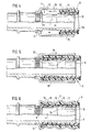
- Figure 1 shows one made of metal or plastic manufactured nipple 1, which is used to connect a refrigerant hose, e.g. for air conditioning systems of motor vehicles shall be.
- the nipple 1 has an approximately cylindrical Zone 2, a ramp 3 rising from this zone with a retaining edge 3a for the hose and one behind it Zone 4, which is bounded by a federal government 20, behind a neck piece with knurling 5 is provided. Of this knurling of the nipple 1 goes into an approximately cylindrical Part 6 about that in the embodiment with a circumferential bead 7 is provided.
- the nipple 1 has the rest a cylindrical through hole 8 on the in not shown the connection between one pushed hose 9 and a connection made becomes.
- Fig. 6 which shows the completed fitting, i.e. so that The nipple with the hose 9 pushed on shows that that the nipple 1 from a hose socket 10 from a deformable metal, for example aluminum, is surrounded, which with a connector 11 of smaller diameter on the Knurling 5 is placed and pressed there by one twist to prevent and establish a positive connection.
- a deformable metal for example aluminum
- the hose 9 consists of several layers 14, 14a, 15 and 16, of which the innermost layer 16 is an inner lining made of polyamide is.
- This inner lining 16 is of an intermediate layer 14a encased, which in turn by a reinforcement 15 is surrounded.
- This layer of reinforcement 15 is still surrounded by an outer layer 14.
- Such hoses with a polyamide inner lining are difficult to reinforce.
- the invention is particularly suitable for this.
- the approximately cylindrical zone 4 of the nipple 1 is shown in FIG. 1 first in the direction of arrow 17 with an adhesive strip wound.
- This adhesive strip which is not shown in detail in FIG. 1 is a strip of an acrylic adhesive, as for example under the name 3M VHB adhesive film is on the market.
- This tape is there made of acrylic adhesive in film form without backing material.
- the Adhesive has a very high temperature resistance. He is also resistant to solvents and UV light, as well as Weather influences, aging and plasticizers. It doesn't find any Curing instead.
- the adhesive remains viscoelastic and unchanged in its nature. He needs a certain one Dwell time in the surface roughness the contact surfaces of zone 4 facing him can flow. The dwell time can be reduced by increasing the temperature.
- this adhesive strip can be cut to length Strip 21, the width of which is somewhat smaller than the length of zone 4. In the illustrated embodiment corresponds almost the width of the adhesive strip 21 the length of zone 4. It has been shown that a Width is sufficient if it is only about two thirds of the Length of zone 4 corresponds.
- the length of the adhesive strip 21 is 2 ⁇ ⁇ r + b, where r is the radius of the nipple in the area is zone 4 and b gives a measure by which the in a Winding applied strips 21 at its ends 21a, 21b overlap each other.
- the adhesive strip 21 As shown in broken lines is, it would also be possible to use the adhesive strip 21 to provide slanted end edges 21a 'and 21b' and then in to apply a winding so that even then the ends overlap a little, but not the overlap seam along one Surface line in zone 4, but obliquely to one runs.
- the arrow 24 indicates that the adhesive strip 21, if it is applied to zone 4 with its edge 21a, is wrapped around the zone until its end is the applied one Slightly overlapped at the end of 21a. 2 shows that the Adhesive strip 21 with its right longitudinal edge 21c on the Holding edge 3a of ramp 3 abuts. This has the following Slip-on process of the hose according to FIG. 4 meaning insofar as it avoids that when postponed of the hose the adhesive strips are pushed off from zone 4 can be.
- Fig. 3 shows a variant of the winding process, as he is shown schematically in Fig. 1.
- an adhesive strip 22 used much smaller width, the with one of its longitudinal edges 22c now also subsequently to the holding edge 3a of the ramp 3 with a first winding, which does not have to be fully 360 °.
- the Strip 22, for example of a not shown Roll can be processed, is then as shown helical so on those already in Zone 4 Strip windings wound that the edge 22c over partially overlaying the existing winding.
- she should but up to two thirds of the length, starting from the Retaining edge 3a be applied. This can also be done happen that, for example, the nipple 1 in the direction of the arrow 23 is rotated so that the adhesive strip 22 accordingly is pulled off the roll and wound up.
- the nipple according to Fig. 1, 2 or 3 in the described Way is provided with the adhesive layer
- the nipple 4 provided with the hose socket 10, which also as the end of the hose 9 axially in the direction of the arrow 18 is pushed onto the nipple. Training the Ramp 3 prevents this axial postponing that from the front edge of the hose 9 the applied adhesive layer is pushed away.
- FIG. 5 shows in the detail shown, is the inner layer 16 of the hose 9 largely contactless over the adhesive layer then present in zone 4 19 pushed away until the hose on the collar 20 (Fig. 3) comes to the plant.
- the hose socket according to FIG. 6 10 pressed, with at least one bead 12, - or a corresponding wider bead - better, as shown two sikken 12, in the area of zone 4, i.e. in the area of the applied Adhesive layer 19, may be provided to the inner layer 16 of the hose 9 firmly and permanently against the Press adhesive layer 19.
- the new hose fitting is therefore done. It is permanent and dense.
Landscapes
- Engineering & Computer Science (AREA)
- General Engineering & Computer Science (AREA)
- Mechanical Engineering (AREA)
- Rigid Pipes And Flexible Pipes (AREA)
- Coating Apparatus (AREA)
- Closures For Containers (AREA)
- Joints That Cut Off Fluids, And Hose Joints (AREA)
Description
- Fig. 1
- die schematische Darstellung des Aufwickelns eines Klebestreifens auf eine Zone eines Nipppels einer erfindungsgemäß ausgestalteten Armatur,
- Fig. 2
- die Darstellung des Aufwickelvorganges mit einem auf Länge geschnittenen Klebestreifen,
- Fig. 3
- die Darstellung des Aufwickelvorganges mit einem wendelförmig gewickelten Klebestreifen,
- Fig. 4
- den Vorgang des axialen Aufschiebens des Schlauches auf den nach den Fig. 1, 2 oder 3 vorbereiteten Nippel,
- Fig. 5
- den aufgeschobenen Schlauch in seiner Endstellung und
- Fig. 6
- die fertiggestellte Armatur mit verpreßter Schlauchfassung.
Claims (10)
- Armatur mit einem Nippel (1) zum Anschluß eines Schlauches (9) und mit einer Schlauchfassung (10), die den Schlauch im Bereich des Nippels umgibt und mit Preßsicken (12, 13) gegen den Schlauch gedrückt ist, die auf die mit umlaufenden Rampen (3) und Haltekanten versehene Nippelkontur abgestimmt sind, wobei mindestens eine der in Aufschieberichtung des Schlauches hinter einer Rampe (3) gelegenen Zonen (4) mit einem Abdichtmaterial versehen ist, dadurch gekennzeichnet, daß als Abdichtmaterial ein Klebefilm vorgesehen ist, der in Streifenform (17) auf den Nippel (1) aufgewickelt ist.
- Armatur nach Anspruch 1, dadurch gekennzeichnet, daß der Klebefilmstreifen (21, 22) aus einem Transferklebstoff ohne Trägermaterial besteht.
- Armatur nach Anspruch 2, dadurch gekennzeichnet, daß als Transferklebstoff ein Acrylatklebstoff in Filmform vorgesehen ist.
- Armatur nach einem der Ansprüche 1 bis 3, dadurch gekennzeichnet, daß der Klebefilmstreifen (21) eine Breite aufweist, die kleiner ist als die Länge (1) der Zone (4) des Nippels (1), insbesondere nur etwa 2/3 dieser Länge beträgt, und daß eine Seitenkante (21c) des Klebefilms etwa bündig zu der Haltekante (3a) der Rampe verläuft.
- Armatur nach einem der Ansprüche 1 bis 3, dadurch gekennzeichnet, daß der Klebefilmstreifen (21) eine Breite aufweist, die der Länge (1) der Zone (4) des Nippels (1) in etwa entspricht.
- Armatur nach einem der Ansprüche 1 bis 3, dadurch gekennzeichnet, daß die Enden (21a', 21b') des Klebestreifen (21) schräg geschnitten sind.
- Armatur nach einem der Ansprüche 4 bis 6, dadurch gekennzeichnet, daß die freien Enden (21a, 21b) des Klebestreifens (21) sich mindestens über einen Teil (b) der Streifenlänge gegenseitig überlappen.
- Armatur nach einem der Ansprüche 1 bis 3, dadurch gekennzeichnet, daß der Klebestreifen (22) in mehr als einer Wicklung aufgebracht und wendelförmig aufgewickelt ist.
- Armatur nach Anspruch 8, dadurch gekennzeichnet, daß die benachbarten Wicklungen sich teilweise überlappen.
- Armatur nach Anspruch 1, dadurch gekennzeichnet, daß die Schlauchfassung (10) im Bereich der mit dem Klebefilm (19) versehenen Zone (4) des Nippels (1) mit mindestens einer Sikke (12) gegen den Nippel gedrückt ist.
Applications Claiming Priority (3)
| Application Number | Priority Date | Filing Date | Title |
|---|---|---|---|
| DE19756675 | 1997-12-19 | ||
| DE19756675A DE19756675C1 (de) | 1997-12-19 | 1997-12-19 | Armatur zum Anschluß eines Schlauches |
| PCT/EP1998/007831 WO1999032822A1 (de) | 1997-12-19 | 1998-12-02 | Armatur zum anschluss eines schlauches |
Publications (2)
| Publication Number | Publication Date |
|---|---|
| EP1040294A1 EP1040294A1 (de) | 2000-10-04 |
| EP1040294B1 true EP1040294B1 (de) | 2002-11-13 |
Family
ID=7852610
Family Applications (1)
| Application Number | Title | Priority Date | Filing Date |
|---|---|---|---|
| EP98965739A Expired - Lifetime EP1040294B1 (de) | 1997-12-19 | 1998-12-02 | Armatur zum anschluss eines schlauches |
Country Status (7)
| Country | Link |
|---|---|
| EP (1) | EP1040294B1 (de) |
| AR (1) | AR010970A1 (de) |
| AT (1) | ATE227818T1 (de) |
| DE (2) | DE19756675C1 (de) |
| ES (1) | ES2190137T3 (de) |
| WO (1) | WO1999032822A1 (de) |
| ZA (1) | ZA9811056B (de) |
Families Citing this family (4)
| Publication number | Priority date | Publication date | Assignee | Title |
|---|---|---|---|---|
| FR2804741B1 (fr) * | 2000-02-09 | 2002-08-30 | Thiebaut Zeller | Raccordement pour conduits souples et son procede de mise en oeuvre |
| CN100425899C (zh) * | 2003-06-12 | 2008-10-15 | 伊利诺斯器械工程公司 | 管接头 |
| WO2008149391A1 (en) * | 2007-06-05 | 2008-12-11 | Dayco Fluid Technologies S.P.A. | Improved flexible conduit for a low pressure circuit of a power steering system |
| ITTO20120296A1 (it) * | 2012-04-04 | 2013-10-05 | Quasar S P A | Antivibrante, in particolare per impianti di refrigerazione o di condizionamento dell¿aria, e metodo per la sua realizzazione. |
Family Cites Families (9)
| Publication number | Priority date | Publication date | Assignee | Title |
|---|---|---|---|---|
| US2220480A (en) * | 1937-03-31 | 1940-11-05 | Electrolux Corp | Hose coupling |
| DE702861C (de) * | 1937-11-17 | 1941-02-18 | Dr Herbert Vohrer | Befestigung eines Schlauches |
| US2453997A (en) * | 1946-05-02 | 1948-11-16 | Resistofiex Corp | Fitting for flexible hose |
| FR81254E (fr) * | 1962-03-03 | 1963-08-23 | Dynaflex | Raccord de tuyau renforcé pour hautes pressions et son procédé de mise en oeuvre |
| US3472536A (en) * | 1968-04-10 | 1969-10-14 | Basil D Ingram | Coupling for connecting a flexible tube to a rigid tube |
| DE3512988A1 (de) * | 1985-04-11 | 1986-10-16 | Phoenix Ag, 2100 Hamburg | Schlauchanschluss |
| DE9102495U1 (de) * | 1991-03-02 | 1991-05-23 | Kühner GmbH & Cie, 7155 Oppenweiler | Armatur zum Anschluß eines Schlauches |
| DE4340450C2 (de) * | 1993-11-27 | 2001-12-20 | Dieter Mueller | Schlaucharmatur bestehend aus Fassung und Nippel für extreme Funktions- und Dichtheitsanforderungen |
| DE9417111U1 (de) * | 1994-10-25 | 1995-01-12 | Jeschke, Immanuel, 31157 Sarstedt | Einführungsvorrichtung für eine Gasleitung in ein Gebäude |
-
1997
- 1997-12-19 DE DE19756675A patent/DE19756675C1/de not_active Expired - Fee Related
-
1998
- 1998-12-02 AT AT98965739T patent/ATE227818T1/de not_active IP Right Cessation
- 1998-12-02 DE DE59806299T patent/DE59806299D1/de not_active Expired - Fee Related
- 1998-12-02 WO PCT/EP1998/007831 patent/WO1999032822A1/de not_active Ceased
- 1998-12-02 EP EP98965739A patent/EP1040294B1/de not_active Expired - Lifetime
- 1998-12-02 ES ES98965739T patent/ES2190137T3/es not_active Expired - Lifetime
- 1998-12-03 ZA ZA9811056A patent/ZA9811056B/xx unknown
- 1998-12-18 AR ARP980106469A patent/AR010970A1/es active IP Right Grant
Also Published As
| Publication number | Publication date |
|---|---|
| ES2190137T3 (es) | 2003-07-16 |
| ATE227818T1 (de) | 2002-11-15 |
| AR010970A1 (es) | 2000-07-12 |
| DE19756675C1 (de) | 1999-07-22 |
| ZA9811056B (en) | 1999-06-07 |
| WO1999032822A1 (de) | 1999-07-01 |
| EP1040294A1 (de) | 2000-10-04 |
| DE59806299D1 (de) | 2002-12-19 |
Similar Documents
| Publication | Publication Date | Title |
|---|---|---|
| DE3815173C2 (de) | ||
| AT392338B (de) | Klappenventil | |
| DE69002721T2 (de) | Rohrverbindung. | |
| EP0611911A1 (de) | Abdichtende Verbindung von Kunststoff-Metall-Kunststoff-Verbundrohren | |
| DE69300936T2 (de) | Verbindung für Metallrohre. | |
| DE102010010765A1 (de) | Vorrichtung und Verfahren zum Verbinden einer ein Fluid führenden Leitung mit einem benachbarten Bauteil | |
| DE3435564A1 (de) | Schlauchhalter | |
| EP0557594A1 (de) | Verfahren zum Montieren eines Anschlusselementes | |
| DE19756675C1 (de) | Armatur zum Anschluß eines Schlauches | |
| DE29901935U1 (de) | Leitungssystem | |
| DE19845720C2 (de) | Anschlußelement | |
| EP0441466A2 (de) | Doppelwandhohlkörper mit Zwischenlage und Verfahren zur Herstellung desselben | |
| EP1306601B1 (de) | Pressfitting für den Anschluss mindestens eines Rohres | |
| DE2943665C2 (de) | ||
| DE2010501C2 (de) | Zylinderanordnung | |
| DE69008909T2 (de) | Verbindungsmittel für eine Farbrollerwiederladung und Farbroller mit dieser Wiederladung. | |
| DE3729056C2 (de) | ||
| EP0897081B1 (de) | Anschlussvorrichtung für ein Kunststoffrohr | |
| EP0472056B1 (de) | Verbindungselement für Rohre | |
| DE2600621C3 (de) | Gewindelose Verbindung für Rohre und Verfahren zu ihrer Herstellung | |
| DE1932447U (de) | Drehbare kupplungszwinge fuer schlaeuche. | |
| DE19523506A1 (de) | Leitungselement zur flexiblen Verbindung zweier Rohrleitungen | |
| CH669981A5 (de) | ||
| EP1705270A2 (de) | Aufsteckhülse | |
| DE3341618A1 (de) | Stirnseitige abdichtung einer schrumpfbaren kabelgarnitur |
Legal Events
| Date | Code | Title | Description |
|---|---|---|---|
| PUAI | Public reference made under article 153(3) epc to a published international application that has entered the european phase |
Free format text: ORIGINAL CODE: 0009012 |
|
| 17P | Request for examination filed |
Effective date: 20000513 |
|
| AK | Designated contracting states |
Kind code of ref document: A1 Designated state(s): AT BE CH CY DE DK ES FI FR GB GR IE IT LI LU MC NL PT SE |
|
| GRAG | Despatch of communication of intention to grant |
Free format text: ORIGINAL CODE: EPIDOS AGRA |
|
| 17Q | First examination report despatched |
Effective date: 20020225 |
|
| GRAG | Despatch of communication of intention to grant |
Free format text: ORIGINAL CODE: EPIDOS AGRA |
|
| GRAH | Despatch of communication of intention to grant a patent |
Free format text: ORIGINAL CODE: EPIDOS IGRA |
|
| GRAH | Despatch of communication of intention to grant a patent |
Free format text: ORIGINAL CODE: EPIDOS IGRA |
|
| GRAA | (expected) grant |
Free format text: ORIGINAL CODE: 0009210 |
|
| AK | Designated contracting states |
Kind code of ref document: B1 Designated state(s): AT BE CH CY DE DK ES FI FR GB GR IE IT LI LU MC NL PT SE |
|
| PG25 | Lapsed in a contracting state [announced via postgrant information from national office to epo] |
Ref country code: NL Free format text: LAPSE BECAUSE OF FAILURE TO SUBMIT A TRANSLATION OF THE DESCRIPTION OR TO PAY THE FEE WITHIN THE PRESCRIBED TIME-LIMIT Effective date: 20021113 Ref country code: IT Free format text: LAPSE BECAUSE OF FAILURE TO SUBMIT A TRANSLATION OF THE DESCRIPTION OR TO PAY THE FEE WITHIN THE PRESCRIBED TIME-LIMIT;WARNING: LAPSES OF ITALIAN PATENTS WITH EFFECTIVE DATE BEFORE 2007 MAY HAVE OCCURRED AT ANY TIME BEFORE 2007. THE CORRECT EFFECTIVE DATE MAY BE DIFFERENT FROM THE ONE RECORDED. Effective date: 20021113 Ref country code: IE Free format text: LAPSE BECAUSE OF FAILURE TO SUBMIT A TRANSLATION OF THE DESCRIPTION OR TO PAY THE FEE WITHIN THE PRESCRIBED TIME-LIMIT Effective date: 20021113 Ref country code: GR Free format text: LAPSE BECAUSE OF FAILURE TO SUBMIT A TRANSLATION OF THE DESCRIPTION OR TO PAY THE FEE WITHIN THE PRESCRIBED TIME-LIMIT Effective date: 20021113 Ref country code: GB Free format text: LAPSE BECAUSE OF FAILURE TO SUBMIT A TRANSLATION OF THE DESCRIPTION OR TO PAY THE FEE WITHIN THE PRESCRIBED TIME-LIMIT Effective date: 20021113 Ref country code: FI Free format text: LAPSE BECAUSE OF FAILURE TO SUBMIT A TRANSLATION OF THE DESCRIPTION OR TO PAY THE FEE WITHIN THE PRESCRIBED TIME-LIMIT Effective date: 20021113 |
|
| REF | Corresponds to: |
Ref document number: 227818 Country of ref document: AT Date of ref document: 20021115 Kind code of ref document: T |
|
| REG | Reference to a national code |
Ref country code: GB Ref legal event code: FG4D Free format text: NOT ENGLISH |
|
| REG | Reference to a national code |
Ref country code: CH Ref legal event code: EP |
|
| PG25 | Lapsed in a contracting state [announced via postgrant information from national office to epo] |
Ref country code: LU Free format text: LAPSE BECAUSE OF NON-PAYMENT OF DUE FEES Effective date: 20021202 Ref country code: AT Free format text: LAPSE BECAUSE OF NON-PAYMENT OF DUE FEES Effective date: 20021202 |
|
| REG | Reference to a national code |
Ref country code: IE Ref legal event code: FG4D Free format text: GERMAN |
|
| REF | Corresponds to: |
Ref document number: 59806299 Country of ref document: DE Date of ref document: 20021219 |
|
| PG25 | Lapsed in a contracting state [announced via postgrant information from national office to epo] |
Ref country code: LI Free format text: LAPSE BECAUSE OF NON-PAYMENT OF DUE FEES Effective date: 20021231 Ref country code: CY Free format text: LAPSE BECAUSE OF FAILURE TO SUBMIT A TRANSLATION OF THE DESCRIPTION OR TO PAY THE FEE WITHIN THE PRESCRIBED TIME-LIMIT Effective date: 20021231 Ref country code: CH Free format text: LAPSE BECAUSE OF NON-PAYMENT OF DUE FEES Effective date: 20021231 Ref country code: BE Free format text: LAPSE BECAUSE OF NON-PAYMENT OF DUE FEES Effective date: 20021231 |
|
| PG25 | Lapsed in a contracting state [announced via postgrant information from national office to epo] |
Ref country code: PT Free format text: LAPSE BECAUSE OF FAILURE TO SUBMIT A TRANSLATION OF THE DESCRIPTION OR TO PAY THE FEE WITHIN THE PRESCRIBED TIME-LIMIT Effective date: 20030213 Ref country code: DK Free format text: LAPSE BECAUSE OF FAILURE TO SUBMIT A TRANSLATION OF THE DESCRIPTION OR TO PAY THE FEE WITHIN THE PRESCRIBED TIME-LIMIT Effective date: 20030213 |
|
| NLV1 | Nl: lapsed or annulled due to failure to fulfill the requirements of art. 29p and 29m of the patents act | ||
| GBV | Gb: ep patent (uk) treated as always having been void in accordance with gb section 77(7)/1977 [no translation filed] |
Effective date: 20021113 |
|
| BERE | Be: lapsed |
Owner name: *KUHNER G.M.B.H. & CIE Effective date: 20021231 |
|
| PG25 | Lapsed in a contracting state [announced via postgrant information from national office to epo] |
Ref country code: MC Free format text: LAPSE BECAUSE OF NON-PAYMENT OF DUE FEES Effective date: 20030701 |
|
| ET | Fr: translation filed | ||
| REG | Reference to a national code |
Ref country code: ES Ref legal event code: FG2A Ref document number: 2190137 Country of ref document: ES Kind code of ref document: T3 |
|
| RAP2 | Party data changed (patent owner data changed or rights of a patent transferred) |
Owner name: CONTITECH KUEHNER GMBH & CIE. KG |
|
| REG | Reference to a national code |
Ref country code: IE Ref legal event code: FD4D Ref document number: 1040294E Country of ref document: IE |
|
| REG | Reference to a national code |
Ref country code: CH Ref legal event code: PL |
|
| PLBE | No opposition filed within time limit |
Free format text: ORIGINAL CODE: 0009261 |
|
| STAA | Information on the status of an ep patent application or granted ep patent |
Free format text: STATUS: NO OPPOSITION FILED WITHIN TIME LIMIT |
|
| 26N | No opposition filed |
Effective date: 20030814 |
|
| PGFP | Annual fee paid to national office [announced via postgrant information from national office to epo] |
Ref country code: SE Payment date: 20071213 Year of fee payment: 10 |
|
| PGFP | Annual fee paid to national office [announced via postgrant information from national office to epo] |
Ref country code: ES Payment date: 20071228 Year of fee payment: 10 |
|
| PGFP | Annual fee paid to national office [announced via postgrant information from national office to epo] |
Ref country code: DE Payment date: 20071103 Year of fee payment: 10 |
|
| PGFP | Annual fee paid to national office [announced via postgrant information from national office to epo] |
Ref country code: FR Payment date: 20071217 Year of fee payment: 10 |
|
| EUG | Se: european patent has lapsed | ||
| REG | Reference to a national code |
Ref country code: FR Ref legal event code: ST Effective date: 20090831 |
|
| PG25 | Lapsed in a contracting state [announced via postgrant information from national office to epo] |
Ref country code: DE Free format text: LAPSE BECAUSE OF NON-PAYMENT OF DUE FEES Effective date: 20090701 |
|
| REG | Reference to a national code |
Ref country code: ES Ref legal event code: FD2A Effective date: 20081203 |
|
| PG25 | Lapsed in a contracting state [announced via postgrant information from national office to epo] |
Ref country code: FR Free format text: LAPSE BECAUSE OF NON-PAYMENT OF DUE FEES Effective date: 20081231 Ref country code: ES Free format text: LAPSE BECAUSE OF NON-PAYMENT OF DUE FEES Effective date: 20081203 |
|
| PG25 | Lapsed in a contracting state [announced via postgrant information from national office to epo] |
Ref country code: SE Free format text: LAPSE BECAUSE OF NON-PAYMENT OF DUE FEES Effective date: 20081203 |