EP1040273B1 - Druckventilfeder - Google Patents
Druckventilfeder Download PDFInfo
- Publication number
- EP1040273B1 EP1040273B1 EP98958119A EP98958119A EP1040273B1 EP 1040273 B1 EP1040273 B1 EP 1040273B1 EP 98958119 A EP98958119 A EP 98958119A EP 98958119 A EP98958119 A EP 98958119A EP 1040273 B1 EP1040273 B1 EP 1040273B1
- Authority
- EP
- European Patent Office
- Prior art keywords
- holding
- valve
- down member
- pressure valve
- pins
- Prior art date
- Legal status (The legal status is an assumption and is not a legal conclusion. Google has not performed a legal analysis and makes no representation as to the accuracy of the status listed.)
- Expired - Lifetime
Links
- 238000013016 damping Methods 0.000 claims description 5
- 238000003780 insertion Methods 0.000 claims description 3
- 230000037431 insertion Effects 0.000 claims description 3
- 235000014676 Phragmites communis Nutrition 0.000 claims 3
- 238000005057 refrigeration Methods 0.000 claims 1
- 238000004519 manufacturing process Methods 0.000 description 7
- 230000006835 compression Effects 0.000 description 3
- 238000007906 compression Methods 0.000 description 3
- 238000005056 compaction Methods 0.000 description 2
- 238000010276 construction Methods 0.000 description 1
- 230000005611 electricity Effects 0.000 description 1
- 238000005516 engineering process Methods 0.000 description 1
- 238000003754 machining Methods 0.000 description 1
- 238000000034 method Methods 0.000 description 1
- 230000036316 preload Effects 0.000 description 1
- 230000003584 silencer Effects 0.000 description 1
- 230000003746 surface roughness Effects 0.000 description 1
- 238000004804 winding Methods 0.000 description 1
Images




Classifications
-
- F—MECHANICAL ENGINEERING; LIGHTING; HEATING; WEAPONS; BLASTING
- F04—POSITIVE - DISPLACEMENT MACHINES FOR LIQUIDS; PUMPS FOR LIQUIDS OR ELASTIC FLUIDS
- F04B—POSITIVE-DISPLACEMENT MACHINES FOR LIQUIDS; PUMPS
- F04B39/00—Component parts, details, or accessories, of pumps or pumping systems specially adapted for elastic fluids, not otherwise provided for in, or of interest apart from, groups F04B25/00 - F04B37/00
- F04B39/10—Adaptations or arrangements of distribution members
- F04B39/1073—Adaptations or arrangements of distribution members the members being reed valves
-
- F—MECHANICAL ENGINEERING; LIGHTING; HEATING; WEAPONS; BLASTING
- F16—ENGINEERING ELEMENTS AND UNITS; GENERAL MEASURES FOR PRODUCING AND MAINTAINING EFFECTIVE FUNCTIONING OF MACHINES OR INSTALLATIONS; THERMAL INSULATION IN GENERAL
- F16K—VALVES; TAPS; COCKS; ACTUATING-FLOATS; DEVICES FOR VENTING OR AERATING
- F16K15/00—Check valves
- F16K15/14—Check valves with flexible valve members
- F16K15/16—Check valves with flexible valve members with tongue-shaped laminae
- F16K15/162—Check valves with flexible valve members with tongue-shaped laminae with limit stop
-
- F—MECHANICAL ENGINEERING; LIGHTING; HEATING; WEAPONS; BLASTING
- F16—ENGINEERING ELEMENTS AND UNITS; GENERAL MEASURES FOR PRODUCING AND MAINTAINING EFFECTIVE FUNCTIONING OF MACHINES OR INSTALLATIONS; THERMAL INSULATION IN GENERAL
- F16K—VALVES; TAPS; COCKS; ACTUATING-FLOATS; DEVICES FOR VENTING OR AERATING
- F16K17/00—Safety valves; Equalising valves, e.g. pressure relief valves
- F16K17/02—Safety valves; Equalising valves, e.g. pressure relief valves opening on surplus pressure on one side; closing on insufficient pressure on one side
- F16K17/04—Safety valves; Equalising valves, e.g. pressure relief valves opening on surplus pressure on one side; closing on insufficient pressure on one side spring-loaded
-
- F—MECHANICAL ENGINEERING; LIGHTING; HEATING; WEAPONS; BLASTING
- F16—ENGINEERING ELEMENTS AND UNITS; GENERAL MEASURES FOR PRODUCING AND MAINTAINING EFFECTIVE FUNCTIONING OF MACHINES OR INSTALLATIONS; THERMAL INSULATION IN GENERAL
- F16K—VALVES; TAPS; COCKS; ACTUATING-FLOATS; DEVICES FOR VENTING OR AERATING
- F16K47/00—Means in valves for absorbing fluid energy
- F16K47/01—Damping of valve members
- F16K47/011—Damping of valve members by means of a dashpot
- F16K47/0111—Damping of valve members by means of a dashpot the valve members comprising a plunger sliding within a fixed dashpot
-
- Y—GENERAL TAGGING OF NEW TECHNOLOGICAL DEVELOPMENTS; GENERAL TAGGING OF CROSS-SECTIONAL TECHNOLOGIES SPANNING OVER SEVERAL SECTIONS OF THE IPC; TECHNICAL SUBJECTS COVERED BY FORMER USPC CROSS-REFERENCE ART COLLECTIONS [XRACs] AND DIGESTS
- Y10—TECHNICAL SUBJECTS COVERED BY FORMER USPC
- Y10T—TECHNICAL SUBJECTS COVERED BY FORMER US CLASSIFICATION
- Y10T137/00—Fluid handling
- Y10T137/0318—Processes
- Y10T137/0402—Cleaning, repairing, or assembling
- Y10T137/0491—Valve or valve element assembling, disassembling, or replacing
-
- Y—GENERAL TAGGING OF NEW TECHNOLOGICAL DEVELOPMENTS; GENERAL TAGGING OF CROSS-SECTIONAL TECHNOLOGIES SPANNING OVER SEVERAL SECTIONS OF THE IPC; TECHNICAL SUBJECTS COVERED BY FORMER USPC CROSS-REFERENCE ART COLLECTIONS [XRACs] AND DIGESTS
- Y10—TECHNICAL SUBJECTS COVERED BY FORMER USPC
- Y10T—TECHNICAL SUBJECTS COVERED BY FORMER US CLASSIFICATION
- Y10T137/00—Fluid handling
- Y10T137/7504—Removable valve head and seat unit
- Y10T137/7559—Pump type
-
- Y—GENERAL TAGGING OF NEW TECHNOLOGICAL DEVELOPMENTS; GENERAL TAGGING OF CROSS-SECTIONAL TECHNOLOGIES SPANNING OVER SEVERAL SECTIONS OF THE IPC; TECHNICAL SUBJECTS COVERED BY FORMER USPC CROSS-REFERENCE ART COLLECTIONS [XRACs] AND DIGESTS
- Y10—TECHNICAL SUBJECTS COVERED BY FORMER USPC
- Y10T—TECHNICAL SUBJECTS COVERED BY FORMER US CLASSIFICATION
- Y10T137/00—Fluid handling
- Y10T137/7722—Line condition change responsive valves
- Y10T137/7837—Direct response valves [i.e., check valve type]
- Y10T137/785—With retarder or dashpot
-
- Y—GENERAL TAGGING OF NEW TECHNOLOGICAL DEVELOPMENTS; GENERAL TAGGING OF CROSS-SECTIONAL TECHNOLOGIES SPANNING OVER SEVERAL SECTIONS OF THE IPC; TECHNICAL SUBJECTS COVERED BY FORMER USPC CROSS-REFERENCE ART COLLECTIONS [XRACs] AND DIGESTS
- Y10—TECHNICAL SUBJECTS COVERED BY FORMER USPC
- Y10T—TECHNICAL SUBJECTS COVERED BY FORMER US CLASSIFICATION
- Y10T137/00—Fluid handling
- Y10T137/7722—Line condition change responsive valves
- Y10T137/7837—Direct response valves [i.e., check valve type]
- Y10T137/7879—Resilient material valve
- Y10T137/7888—With valve member flexing about securement
- Y10T137/7891—Flap or reed
- Y10T137/7892—With stop
Definitions
- the invention relates to a pressure valve for a Compressor according to claim 1.
- Pressure valves of this type are located on the pressure side of compressors.
- known pressure valves according to the state the technology are above a pressure hole of a valve plate a valve spring, not necessarily a damper element and a hold-down element arranged, an element above the others. All elements are in that of valve plate and cylinder cover enclosed volume, whereby both are attached to the cylinder with screws.
- At the Compression cycle of the compressor opens the valve spring by the pressure of the medium in the pressure bore and the spring folds up. It is not necessarily of braked a damper element.
- the stroke of the valve spring is also not necessarily by means of a hold-down element limited. When the compression cycle is finished, the spring works due to the spring force and the pressure difference the pressure hole and closes it.
- US-A-5 110 272 discloses a pressure valve which is a valve spring, a damper element and a pins having hold-down element.
- the disadvantage compared to the pressure valve according to the invention is that The fact that there is a recess in the valve plate is which complicates the processing and additionally that Hold-down element by means of rivets on the valve plate must be attached.
- Pressure valve means this for a number of several Millions a year a much longer manufacturing time and much more material that has to be processed.
- DE 33 05 791 A1 also has a pressure valve for discloses a compressor in which the valve plate is a has elongated recess into which an insert is inserted is on which pins are arranged. These pens are normal to the level of the valve plate and the insert.
- the valve spring, the damper element and the hold-down elements are included Provide recesses that engage these pins are feasible. This will place these items in your position fixed.
- the disadvantage of this type of pressure valve is that complex manufacturing. There must be one on the valve plate first oblong recess are milled, taking care must be that the surface roughness on the valve seat specified tolerances. Subsequently however, an insert must be made that fits in the previous milled elongated recess is used. That Volume of material that is first removed by machining then partially replenished.
- the entire pressure valve also includes an insert, a valve spring, a Additional leaf spring, a catch plate and a bridge spring, thus five parts which require considerable assembly effort mean.
- valve plates are also known, the valve plate of which is none Has recess, but where the valve spring, that Damper element and the one or more hold-down elements Rivets are attached to the valve plate.
- construction also means an additional one Manufacturing effort, since at least one riveting machine is used must come. Also disassembling this arrangement is for Repair purposes due to the rivets difficult if not at all impossible. Pre-assembly of the valve plate including valve spring, Damper element and hold-down element is not possible because it is loosely assembled parts that a not easy handling of the resulting unit allows.
- DE-AS 1 503 406 discloses a valve arrangement at the one above a pressure valve leaf spring Stop plate and a tension spring are arranged. This Elements are engaged with two pins that are in holes in the valve plate and in the cylinder cover and so the Ensure cohesion of the arrangement
- the present invention has two particular disadvantages.
- the complex fastening of the pressure valve leaf spring by means of four parts instead of one as in this one Registration leads to a much higher one Manufacturing effort and increases the likelihood of Failure of the entire pressure valve.
- the opening valve spring experiences no damping, whereas in the present application the possibility of attaching a damper element taken into consideration.
- DE-AS 1 503 406 has two separate ones Suction chambers disclosed, as well as a central pressure hole. This leads to greater suction gas preheating, which in turn leads to leads to an increased compaction work.
- the aim of the present invention is to provide a pressure valve provide that the disadvantages described above are avoided and simply plug the different components together enables, which at the same time the valve spring, the Damper element and the hold-down element, without each other additional tools attached, the manufacturing effort significantly reduced and the probability of failure minimized.
- the flat manufacture of the valve plate means that there is no need complete operation.
- the special arrangement of the pins on Hold-down element opposite the corresponding holes in the valve plate allows fixing the Hold-down element, the valve spring and the Damper element on the valve plate, creating additional Fasteners such as rivets are not necessary and therefore not only weight (material) is saved, but again the manufacturing time can be shortened.
- the hold-down element after Assemble the pressure valve through the cylinder cover in its middle area pressed against the valve plate to the Loosening the hold-down element by operational To prevent vibrations.
- Claim 3 and 4 prevents incorrect mounting of the Hold-down device on the valve plate due to the asymmetrical Shape. Confusion regarding the direction of insertion as well Difficulties with the valve spring and the Damper element that results from incorrect assembly, can due to the fact that only one insertion direction is possible to be excluded. Furthermore, the am Hold-down element molded pins accurate Positioning the valve spring or the damper element.
- Claims 5 to 8 enable stable fastening both the hold-down element on the valve plate and the valve spring or the damper element on the pins of the Hold-down element. Slipping of these components Assembly of the valve plate with the cylinder cover is thus not possible anymore.
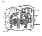
- FIG. 1 shows a sectional view through a compressor the state of the art. Via an electric motor with rotor 1, Air gap 2 and stator windings 5, the pressure springs 4 is stored and via the bushing 7 with electricity is supplied, a crankshaft 3 is driven, which a connecting rod 12 drives a piston with piston pin 13. This presses the compressed medium in through a pressure hole the valve plate 9 in the space between valve plate 9 and Cylinder cover 10, from where it is again via a pressure line Medium circuit is supplied.
- FIG. 2 shows a hold-down element 21 according to the invention seen.
- An end region 19 is fork-shaped, the other end region 20 is tongue-shaped.
- Pins 18, 16a and 16b are on the underside of the fork-shaped end region 19th arranged.
- In the tongue-shaped end region 20 are also Pins 15 and 17 arranged at the bottom. All Pins are substantially perpendicular to the plane of the Hold-down element. According to the distance Pins slightly different from each other the distance of the Bores 35 from each other in the valve plate 33 for receiving of the pens. This results in when the Hold-down element 21 on the plane according to the invention Valve plate has a preload that keeps the elements on the valve plate is guaranteed even without a cylinder cover.
- the Hold-down element has a U-shaped in a known manner Cross section with angled legs (end regions 19 and 20).
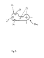
- Fig. 3 shows a valve spring 23.
- the final area 22 are Recesses 24, 25, 26 are provided, the recesses 24 and 26 on the long side of the valve spring and recess 25 is arranged at the end.
- the other end portion is 22a executed circular.
- a damper element 27 can be seen, which in its end regions 28 and 28a in opposite directions, respectively Directions is bent. Corresponding are in the end region 28 Recesses 29, 30 and 31 are provided, the recesses 29 and 31 on the longitudinal edges of the damper element 27 are arranged and the recess 30 on the end face. I End region 28 Are corresponding recesses 29, 30 on the Front side. In the end region 28a there is also an end face arranged recess 32 arranged.
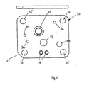
- Fig. 5 shows an elevation and plan view of an inventive essentially square valve plate 33.
- a pressure valve opening Valve seat 34 On a completely flat plate are with a pressure valve opening Valve seat 34, mounting openings 35 for connection with the cylinder cover, hold-down element fastening openings 36, a suction valve opening 37 and fastening openings 38 designed for the suction silencer.
- a corner 39 of the Valve plate is chamfered.
- quadrangular base plate 41 is a cylinder cover wall 42 molded into the middle of one side 43 of the cylinder cover has a passage 44 through which the suction of the Medium.
- FIG. 8 is an assembly view of a Pressure valve according to the invention with valve plate 33 and Cylinder cover 40 can be seen.
- the hold-down element 21 is with its pins 15, 16a, 16b in the valve plate 33 attached.
- the cylinder cover 40 presses on with a web 57 the middle area of the hold-down device and the pressure valve spring 23 is in engagement with the recesses 24, 25, 26 Pins 16a, 16b, 18.
- Cylinder cover 40 and valve plate 33 are connected, for example, by means of screws. The correct alignment of the two elements is done so that the two bevelled corners 39 and 43a to lie one above the other come.
Landscapes
- Engineering & Computer Science (AREA)
- General Engineering & Computer Science (AREA)
- Mechanical Engineering (AREA)
- Compressor (AREA)
- Check Valves (AREA)
Description
- Fig. 1
- eine Schnittansicht eines Verdichters in dem ein erfindungsgemäßes Druckventil zum Einsatz kommt
- Fig. 2
- einen Auf- und Grundriß eines erfindungsgemäßen Niederhalterelementes
- Fig. 3
- einen Grundriß einer Ventilfeder
- Fig. 4
- einen Auf- und Grundriß eines Dämpferelementes
- Fig. 5
- einen Auf- und Grundriß einer erfindungsgemäßen Ventilplatte
- Fig. 6.
- eine Schnittansicht und einen Grundriß eines erfindungsgemäßen Zylinderdeckels
- Fig.7
- eine Untersicht des Zylinderdeckels
- Fig.8
- eine Zusammenstellungsansicht eines erfindungsgemäßen Druckventils
Claims (8)
- Druckventil für einen Verdichter, insbesondere eine hermetisch gekapselte Kleinkältemaschine, das folgende Elemente umfasst: eine Ventilplatte (33), einen eine im wesentlichen viereckige Grundplatte mit angeformten Zylinderwänden, umfassenden Zylinderdeckel (40), wobei Ventilplatte (33) und Zylinderdeckel (40) mittels Befestigungselemente miteinander verbunden sind, sowie eine dazwischen angeordnete Dichtung (58) und im von der Ventilplatte (33) und dem Zylinderdeckel (40) eingeschlossenen Volumen angeordnet eine Ventilfeder (23), ein im wesentlichen u-förmiges, Stifte aufweisendes Niederhalterelement (21) mit ausgewinkelten Schenkeln und wahlweise ein Dämpferelement (27), wobei die Ventilfeder, das Dämpferelement und das Niederhalterelement, in dieser Reihenfolge über einem Ventilsitz angeordnet sind, dadurch gekennzeichnet, daß die Ventilplatte (33) plan ausgeführt ist und Bohrungen (36) aufweist und am Niederhalterelement (21) zu den Bohrungen (36) korrespondierende Stifte (15,16a,16b) ausgebildet sind, wobei der Abstand der Stifte (15,16a,16b) voneinander gegenüber dem Abstand der Bohrungen (36) voneinander geringfügig verschieden ist, so daß beim Aufstecken auf die Ventilplatte (33) eine Vorspannung des Niederhalterelementes stattfindet, die das Halten der Elemente auf der Ventilplatte garantiert.
- Druckventil nach Anspruch 1, dadurch gekennzeichnet, daß der Normalabstand zwischen der Oberseite des erhöhten Mittelbereiches (21a) des Niederhalterelementes (21) und der Auflageebene der Endbereiche (19,20) des Niederhalterelementes (21) mindestens gleich groß oder größer dem bei zusammengebauten Druckventil lichten Abstand zwischen dem Mittelteil des Zylinderdeckels (40) und der Auflageebene der Endbereiche (19,20) des Niederhalterelementes (21) ist, um vom Zylinderdeckel (40) einen Niederhaltedruck auf den Mittelteil (21a) des Niederhalterelementes (21) auszuüben.
- Druckventil nach einem der Ansprüche 1 bis 3, dadurch gekennzeichnet, dass die Endbereiche (19, 20) des Niederhalterelements (21) unterschiedlich geformt sind, vorzugsweise gabelartig (19) bzw. zungenartig (20).
- Druckventil nach einem der Ansprüche 1 bis 4, dadurch gekennzeichnet, dass die Stifte des Niederhalterelements (21) in dessen Endbereichen 19,20 angeordnet sind und sich in die entgegengesetzte Richtung der Schenkel des im wesentlichen u-förmigen Querschnittes des Niederhalterelementes (21) erstrecken.
- Druckventil nach einem der Ansprüche 1 bis 5, dadurch gekennzeichnet, dass im Endbereich (20) des Niederhalters (21) Stifte (15, 17) und im Endbereich (19) je ein Stift (16a, 16b, 18) an den zinkenartigen Ausformungen angeordnet ist.
- Druckventil nach einem der Ansprüche 1 bis 6, dadurch gekennzeichnet, dass die Ventilfeder (23) in ihrem einen Endbereich (22) randoffene Ausnehmungen (24, 25, 26) aufweist, die zur Aufnahme der Stifte (16a, 16b, 18) im gabelartigen Endbereich (19) des Niederhalterelements (21) dienen.
- Druckventil nach einem der Ansprüche 1 bis 7, dadurch gekennzeichnet, dass das vorzugsweise Dämpferelement (27) in seinem einen Endbereich 28 aufgebogen ist und Ausnehmungen (29, 30, 31) aufweist, die zur Aufnahme der Stifte (16a,16b,18) im gabelartigen Endbereich (19) des Niederhalterelementes (21) dienen.
- Druckventil nach einem der Ansprüche 1 bis 8, dadurch gekennzeichnet, dass das Dämpferelement (27) in seinem anderen Endbereich (28a) in die entgegengesetzte Richtung des einen Endbereichs (28) aufgebogen ist und eine Ausnehmung (32) aufweist, die zur Aufnahme des Stiftes (15) im zungenartigen Endbereich (20) des Niederhalterelementes (21) dient.
Applications Claiming Priority (3)
| Application Number | Priority Date | Filing Date | Title |
|---|---|---|---|
| AT213497 | 1997-12-17 | ||
| AT0213497A AT405868B (de) | 1997-12-17 | 1997-12-17 | Druckventil |
| PCT/AT1998/000289 WO1999031387A1 (de) | 1997-12-17 | 1998-11-27 | Druckventilfeder |
Publications (2)
| Publication Number | Publication Date |
|---|---|
| EP1040273A1 EP1040273A1 (de) | 2000-10-04 |
| EP1040273B1 true EP1040273B1 (de) | 2003-01-22 |
Family
ID=3528507
Family Applications (1)
| Application Number | Title | Priority Date | Filing Date |
|---|---|---|---|
| EP98958119A Expired - Lifetime EP1040273B1 (de) | 1997-12-17 | 1998-11-27 | Druckventilfeder |
Country Status (11)
| Country | Link |
|---|---|
| US (1) | US6314990B1 (de) |
| EP (1) | EP1040273B1 (de) |
| JP (1) | JP2002508476A (de) |
| CN (1) | CN1174169C (de) |
| AT (1) | AT405868B (de) |
| BR (1) | BR9813823A (de) |
| DE (1) | DE59807034D1 (de) |
| DK (1) | DK1040273T3 (de) |
| ES (1) | ES2189273T3 (de) |
| SI (1) | SI20338A (de) |
| WO (1) | WO1999031387A1 (de) |
Families Citing this family (9)
| Publication number | Priority date | Publication date | Assignee | Title |
|---|---|---|---|---|
| FR2800831B1 (fr) * | 1999-11-05 | 2002-02-15 | Tecumseh Europe Sa | Dispositif de clapet de refoulement pour compresseur de fluide |
| KR100406640B1 (ko) * | 2001-10-10 | 2003-11-21 | 삼성광주전자 주식회사 | 밀폐형 압축기의 밸브장치 |
| US7018183B2 (en) * | 2002-09-23 | 2006-03-28 | Tecumseh Products Company | Compressor having discharge valve |
| US6832900B2 (en) * | 2003-01-08 | 2004-12-21 | Thomas Industries Inc. | Piston mounting and balancing system |
| US7762796B2 (en) * | 2003-07-23 | 2010-07-27 | Hargraves Technology Corporation | Pump valve with controlled stroke |
| CN100392244C (zh) * | 2006-05-23 | 2008-06-04 | 加西贝拉压缩机有限公司 | 往复式压缩机的阀组结构 |
| DE602006004355D1 (de) * | 2006-10-10 | 2009-01-29 | Magneti Marelli Powertrain Spa | Kraftstoffversorgungssystem mit elektronischer Einspritzung |
| JP2010127100A (ja) * | 2008-11-25 | 2010-06-10 | Daikin Ind Ltd | 吐出弁及び回転式圧縮機 |
| US12180967B1 (en) * | 2023-10-12 | 2024-12-31 | Copeland Lp | Antirotation reed valve systems and methods for compressors |
Family Cites Families (11)
| Publication number | Priority date | Publication date | Assignee | Title |
|---|---|---|---|---|
| GB891313A (en) | 1959-07-29 | 1962-03-14 | Bosch Gmbh Robert | Improvements in or relating to a cylinder block of a pump embodying a vibratory valve assembly |
| US3039487A (en) * | 1960-09-26 | 1962-06-19 | American Motors Corp | Refrigerating apparatus |
| DE1503406B2 (de) | 1965-10-15 | 1974-06-12 | Danfoss A/S, Nordborg (Daenemark) | Ventilanordnung für Kolbenverdichter insbesondere für Kleinkältemaschinen |
| DE3305791C2 (de) * | 1983-02-19 | 1986-02-20 | Danfoss A/S, Nordborg | Druckventil für einen Verdichter |
| IT1234796B (it) * | 1989-06-07 | 1992-05-27 | Aspera Srl | Gruppo valvolare per un compressore alternativo per frigoriferi e simili |
| US5100306A (en) * | 1990-03-16 | 1992-03-31 | Ford Motor Company | Noise reducing compressor gasket and head assembly |
| KR930005874Y1 (ko) | 1991-01-31 | 1993-09-01 | 삼성전자 주식회사 | 압축기 |
| EP0582712B1 (de) * | 1992-03-03 | 1997-02-05 | Matsushita Refrigeration Company | Hermetischer verdichter |
| GB2296961B (en) | 1993-06-17 | 1996-12-04 | White Consolidated Ind Inc | Hermetic refrigeration compressor |
| KR0147004B1 (ko) * | 1995-07-26 | 1998-08-17 | 김광호 | 왕복동형 압축기의 실린더장치 |
| US5769126A (en) * | 1996-09-12 | 1998-06-23 | Samsung Electronics Co., Ltd. | Discharge valve assembly in a reciprocating compressor |
-
1997
- 1997-12-17 AT AT0213497A patent/AT405868B/de not_active IP Right Cessation
-
1998
- 1998-11-27 WO PCT/AT1998/000289 patent/WO1999031387A1/de not_active Ceased
- 1998-11-27 JP JP2000539262A patent/JP2002508476A/ja active Pending
- 1998-11-27 DK DK98958119T patent/DK1040273T3/da active
- 1998-11-27 CN CNB98812307XA patent/CN1174169C/zh not_active Expired - Lifetime
- 1998-11-27 ES ES98958119T patent/ES2189273T3/es not_active Expired - Lifetime
- 1998-11-27 SI SI9820085A patent/SI20338A/sl not_active IP Right Cessation
- 1998-11-27 US US09/581,739 patent/US6314990B1/en not_active Expired - Lifetime
- 1998-11-27 BR BR9813823-5A patent/BR9813823A/pt not_active IP Right Cessation
- 1998-11-27 DE DE59807034T patent/DE59807034D1/de not_active Expired - Lifetime
- 1998-11-27 EP EP98958119A patent/EP1040273B1/de not_active Expired - Lifetime
Also Published As
| Publication number | Publication date |
|---|---|
| BR9813823A (pt) | 2000-10-10 |
| AT405868B (de) | 1999-12-27 |
| DK1040273T3 (da) | 2003-05-05 |
| ES2189273T3 (es) | 2003-07-01 |
| CN1174169C (zh) | 2004-11-03 |
| DE59807034D1 (de) | 2003-02-27 |
| US6314990B1 (en) | 2001-11-13 |
| ATA213497A (de) | 1999-04-15 |
| WO1999031387A1 (de) | 1999-06-24 |
| JP2002508476A (ja) | 2002-03-19 |
| CN1282404A (zh) | 2001-01-31 |
| EP1040273A1 (de) | 2000-10-04 |
| SI20338A (sl) | 2001-02-28 |
Similar Documents
| Publication | Publication Date | Title |
|---|---|---|
| DE69217362T2 (de) | Hermetischer verdichter | |
| DE3623311C2 (de) | ||
| DE4440043C2 (de) | Spiralkompressor | |
| EP3482076B1 (de) | Zylinderkopfdeckel für einen kältemittelkompressor | |
| EP1038107B1 (de) | Kältemittelverdichter mit verbessertem ventil | |
| AT405868B (de) | Druckventil | |
| EP1888918B1 (de) | Kältemittelverdichter | |
| AT5308U1 (de) | Kompressor einer hermetischen kühleinheit mit einem ventilsystem | |
| EP2989326A1 (de) | Pumpenaggregat | |
| DE102016105422A1 (de) | Elektrischer verdichter | |
| EP0065310B1 (de) | Magnetsystem für ein Relais | |
| EP1739297A2 (de) | Zylinderkopfhaube einer Brennkraftmaschine | |
| DE60004525T2 (de) | Saugschalldämpfer für einen hermetischen verdichter | |
| DE10247185B4 (de) | Vorrichtung zum Einstellen des Spiels einer Welle | |
| DE10353040B4 (de) | Flachdichtung mit Fixiervorrichtung | |
| DE202010005247U1 (de) | Lüfterbefestigungseinheit | |
| WO2008017549A1 (de) | Hydroaggregat einer fahrzeugbremsanlage mit einem dichtelement | |
| DE19959021A1 (de) | Elektromagnetisch betätigbares Proportionalventil | |
| EP0912831B1 (de) | Verdichteranlage | |
| DE102008037672A1 (de) | Kolbenverdichter, insbesondere Kältemittelverdichter | |
| WO2006108767A9 (de) | Kältemittelverdichter | |
| DE10223114B4 (de) | Anordnung zur Verbindung einer Kontaktbrücke eines Lenkrades mit einem im Abstand zu diesem angeordneten Kontaktblech | |
| DE202011103246U1 (de) | Befestigung eines Seilantriebsgehäuses auf einem Träger | |
| DE202026100756U1 (de) | Eckverbinder, Rahmenvorrichtung, Rahmen, Schutzstruktur, und Bausatz | |
| DE4141115C2 (de) | Druckventil für einen Kompressor |
Legal Events
| Date | Code | Title | Description |
|---|---|---|---|
| PUAI | Public reference made under article 153(3) epc to a published international application that has entered the european phase |
Free format text: ORIGINAL CODE: 0009012 |
|
| 17P | Request for examination filed |
Effective date: 20000613 |
|
| AK | Designated contracting states |
Kind code of ref document: A1 Designated state(s): DE DK ES FR GB IT |
|
| GRAG | Despatch of communication of intention to grant |
Free format text: ORIGINAL CODE: EPIDOS AGRA |
|
| 17Q | First examination report despatched |
Effective date: 20020326 |
|
| GRAG | Despatch of communication of intention to grant |
Free format text: ORIGINAL CODE: EPIDOS AGRA |
|
| GRAH | Despatch of communication of intention to grant a patent |
Free format text: ORIGINAL CODE: EPIDOS IGRA |
|
| GRAH | Despatch of communication of intention to grant a patent |
Free format text: ORIGINAL CODE: EPIDOS IGRA |
|
| GRAA | (expected) grant |
Free format text: ORIGINAL CODE: 0009210 |
|
| AK | Designated contracting states |
Kind code of ref document: B1 Designated state(s): DE DK ES FR GB IT |
|
| REG | Reference to a national code |
Ref country code: GB Ref legal event code: FG4D Free format text: NOT ENGLISH |
|
| REF | Corresponds to: |
Ref document number: 59807034 Country of ref document: DE Date of ref document: 20030227 Kind code of ref document: P |
|
| REG | Reference to a national code |
Ref country code: DK Ref legal event code: T3 |
|
| GBT | Gb: translation of ep patent filed (gb section 77(6)(a)/1977) |
Effective date: 20030425 |
|
| REG | Reference to a national code |
Ref country code: ES Ref legal event code: FG2A Ref document number: 2189273 Country of ref document: ES Kind code of ref document: T3 |
|
| ET | Fr: translation filed | ||
| PGFP | Annual fee paid to national office [announced via postgrant information from national office to epo] |
Ref country code: FR Payment date: 20031029 Year of fee payment: 6 |
|
| PGFP | Annual fee paid to national office [announced via postgrant information from national office to epo] |
Ref country code: ES Payment date: 20031107 Year of fee payment: 6 |
|
| PGFP | Annual fee paid to national office [announced via postgrant information from national office to epo] |
Ref country code: DK Payment date: 20031119 Year of fee payment: 6 |
|
| PGFP | Annual fee paid to national office [announced via postgrant information from national office to epo] |
Ref country code: GB Payment date: 20031126 Year of fee payment: 6 |
|
| PLBE | No opposition filed within time limit |
Free format text: ORIGINAL CODE: 0009261 |
|
| STAA | Information on the status of an ep patent application or granted ep patent |
Free format text: STATUS: NO OPPOSITION FILED WITHIN TIME LIMIT |
|
| 26N | No opposition filed |
Effective date: 20031023 |
|
| PG25 | Lapsed in a contracting state [announced via postgrant information from national office to epo] |
Ref country code: GB Free format text: LAPSE BECAUSE OF NON-PAYMENT OF DUE FEES Effective date: 20041127 |
|
| PG25 | Lapsed in a contracting state [announced via postgrant information from national office to epo] |
Ref country code: ES Free format text: LAPSE BECAUSE OF NON-PAYMENT OF DUE FEES Effective date: 20041129 |
|
| PG25 | Lapsed in a contracting state [announced via postgrant information from national office to epo] |
Ref country code: DK Free format text: LAPSE BECAUSE OF NON-PAYMENT OF DUE FEES Effective date: 20041130 |
|
| REG | Reference to a national code |
Ref country code: DK Ref legal event code: EBP |
|
| GBPC | Gb: european patent ceased through non-payment of renewal fee |
Effective date: 20041127 |
|
| PG25 | Lapsed in a contracting state [announced via postgrant information from national office to epo] |
Ref country code: FR Free format text: LAPSE BECAUSE OF NON-PAYMENT OF DUE FEES Effective date: 20050729 |
|
| REG | Reference to a national code |
Ref country code: FR Ref legal event code: ST |
|
| PG25 | Lapsed in a contracting state [announced via postgrant information from national office to epo] |
Ref country code: IT Free format text: LAPSE BECAUSE OF NON-PAYMENT OF DUE FEES;WARNING: LAPSES OF ITALIAN PATENTS WITH EFFECTIVE DATE BEFORE 2007 MAY HAVE OCCURRED AT ANY TIME BEFORE 2007. THE CORRECT EFFECTIVE DATE MAY BE DIFFERENT FROM THE ONE RECORDED. Effective date: 20051127 |
|
| REG | Reference to a national code |
Ref country code: ES Ref legal event code: FD2A Effective date: 20041129 |
|
| REG | Reference to a national code |
Representative=s name: KUHNEN & WACKER PATENT- UND RECHTSANWALTSBUERO, DE Ref country code: DE Ref legal event code: R082 Ref document number: 59807034 Country of ref document: DE Effective date: 20140403 Ref country code: DE Ref legal event code: R082 Ref document number: 59807034 Country of ref document: DE Representative=s name: GRUENECKER, KINKELDEY, STOCKMAIR & SCHWANHAEUS, DE Effective date: 20140403 Ref country code: DE Ref legal event code: R081 Ref document number: 59807034 Country of ref document: DE Owner name: SECOP GMBH, DE Free format text: FORMER OWNER: VERDICHTER OE GES.M.B.H., FUERSTENFELD, AT Effective date: 20140403 Ref country code: DE Ref legal event code: R081 Ref document number: 59807034 Country of ref document: DE Owner name: SECOP AUSTRIA GMBH, AT Free format text: FORMER OWNER: VERDICHTER OE GES.M.B.H., FUERSTENFELD, AT Effective date: 20140403 |
|
| REG | Reference to a national code |
Ref country code: DE Ref legal event code: R082 Ref document number: 59807034 Country of ref document: DE Representative=s name: KUHNEN & WACKER PATENT- UND RECHTSANWALTSBUERO, DE Ref country code: DE Ref legal event code: R082 Ref document number: 59807034 Country of ref document: DE |
|
| REG | Reference to a national code |
Ref country code: DE Ref legal event code: R082 Ref document number: 59807034 Country of ref document: DE Representative=s name: KUHNEN & WACKER PATENT- UND RECHTSANWALTSBUERO, DE Ref country code: DE Ref legal event code: R081 Ref document number: 59807034 Country of ref document: DE Owner name: SECOP GMBH, DE Free format text: FORMER OWNER: SECOP AUSTRIA GMBH, FUERSTENFELD, AT |
|
| PGFP | Annual fee paid to national office [announced via postgrant information from national office to epo] |
Ref country code: DE Payment date: 20180131 Year of fee payment: 20 |
|
| REG | Reference to a national code |
Ref country code: DE Ref legal event code: R071 Ref document number: 59807034 Country of ref document: DE |