EP1038452A1 - Einrichtung zum Überführen von pulver- oder granulatförmige Artikel enthaltenden Filterstäben - Google Patents
Einrichtung zum Überführen von pulver- oder granulatförmige Artikel enthaltenden Filterstäben Download PDFInfo
- Publication number
- EP1038452A1 EP1038452A1 EP00105161A EP00105161A EP1038452A1 EP 1038452 A1 EP1038452 A1 EP 1038452A1 EP 00105161 A EP00105161 A EP 00105161A EP 00105161 A EP00105161 A EP 00105161A EP 1038452 A1 EP1038452 A1 EP 1038452A1
- Authority
- EP
- European Patent Office
- Prior art keywords
- line section
- filter rods
- receiving station
- conveyor
- conveyor line
- Prior art date
- Legal status (The legal status is an assumption and is not a legal conclusion. Google has not performed a legal analysis and makes no representation as to the accuracy of the status listed.)
- Granted
Links
- 239000011361 granulated particle Substances 0.000 title 1
- 239000002245 particle Substances 0.000 claims abstract description 18
- OKTJSMMVPCPJKN-UHFFFAOYSA-N Carbon Chemical compound [C] OKTJSMMVPCPJKN-UHFFFAOYSA-N 0.000 claims abstract description 10
- 229910052799 carbon Inorganic materials 0.000 claims abstract description 10
- 241000208125 Nicotiana Species 0.000 claims description 2
- 235000002637 Nicotiana tabacum Nutrition 0.000 claims description 2
- 238000007599 discharging Methods 0.000 claims description 2
- 239000000843 powder Substances 0.000 claims description 2
- 238000007664 blowing Methods 0.000 claims 1
- 230000000979 retarding effect Effects 0.000 abstract 1
- 230000001133 acceleration Effects 0.000 description 5
- 239000000463 material Substances 0.000 description 3
- 238000011144 upstream manufacturing Methods 0.000 description 2
- 239000003610 charcoal Substances 0.000 description 1
- 238000010276 construction Methods 0.000 description 1
- VNWKTOKETHGBQD-UHFFFAOYSA-N methane Chemical compound C VNWKTOKETHGBQD-UHFFFAOYSA-N 0.000 description 1
- 230000002093 peripheral effect Effects 0.000 description 1
- 230000000630 rising effect Effects 0.000 description 1
Images

Classifications
-
- A—HUMAN NECESSITIES
- A24—TOBACCO; CIGARS; CIGARETTES; SIMULATED SMOKING DEVICES; SMOKERS' REQUISITES
- A24C—MACHINES FOR MAKING CIGARS OR CIGARETTES
- A24C5/00—Making cigarettes; Making tipping materials for, or attaching filters or mouthpieces to, cigars or cigarettes
- A24C5/32—Separating, ordering, counting or examining cigarettes; Regulating the feeding of tobacco according to rod or cigarette condition
- A24C5/322—Transporting cigarettes during manufacturing
- A24C5/323—Transporting cigarettes during manufacturing pneumatically
Definitions
- the invention relates to a device for transferring powder or granular Particles, in particular carbon particles, containing filter rods from the tobacco processing industry Industry from a sending station to a receiving station a pneumatic conveying the articles in a longitudinal axial sequence Delivery line, with a free particle collecting and discharging delivery line section.
- the invention is based, free carbon particles independent of the task delivery capacity of the pneumatic delivery line in an effective manner as completely as possible and in good time before entering pollution-prone areas Remove conveyor units.
- the delivery line section provided in the region of the receiving station is interrupted by essentially transverse slots into which blown air ducts aligned with a rising chamber open.
- the conveyor line section has separate conveyor line segments formed by slots formed as radial slots.
- the blown air ducts expediently branch off from a common blown air supply line running parallel to the conveying line section.
- the discharge of the particles collected in the collecting chamber is simplified and facilitated in that the conveying line section - with respect to the conveying direction from top to bottom - is arranged to run essentially vertically with an outlet opening on the underside of the collecting chamber.
- the advantage achieved by the invention is that both at low and even at high conveyor speeds of the filter rods that flow across them Blown air detects and removes all adhering particles, the particles from the virtually unpressurized collecting chamber in this conveyor line section further down can be discharged.
- the conveying device of FIG. 1 essentially consists of a transmitting station 1, a pneumatic conveying line 2 and a receiving station 3, as well as a braking means 4 arranged upstream of the receiving station 3 for reducing the conveying speed of filter rods 6 conveyed by the conveying line and an accelerating means 7 for the individual feeding of the filter rods 6 to the receiving station 3.
- a transmitting station for example, that of the applicant under the name FILIROMAT "offered devices are used.
- a U-shaped curved guide 8 is arranged, the open side of which is covered by a flexible spring plate 9. With such a guide 8, the conveying direction of the filter rods 6 can be confined to a very small space be changed.
- the brake means 4 and the acceleration means 7 are identical in their construction and are described together below.
- the reference symbols for the braking means 4 are provided with the index a and those for the acceleration means 7 have the index b .
- the braking means 4 (acceleration means 7) consists of four rollers 11a, 12a, 13a, 14a (11b, 12b, 13b, 14b), each of which two rollers 11a, 12a (11b, 12b) and 13a, 14a (13b, 14b) ) are arranged one behind the other in the conveying direction (arrow 16) of the filter rods 6 and are looped around by endless belts 17a (17b) or 18a (18b) designed as means for transmitting the braking force (acceleration force) to the filter rods 6.
- the distances between the rollers 11a and 13a (11b and 13b) or 12a and 14a (12b and 14b) are selected so that the belts 17a, 18a on the one hand firmly grip the filter rods 6 but on the other hand do not deform them too much.
- the rollers 11a and 13a (11b and 13b) can be driven by a motor 23 via a belt drive 19a (19b) and a gear pair 21a, 22a (21b, 22b) connecting the rollers 11a and 13a (11b and 13b), the rollers 12a or 14a (12b or 14b) can also be driven via the belts 17a (17b) or 18a (18b).
- the belt drives 19a and 19b are designed such that the rollers 11b and 13b of the accelerating means 7 can be driven at a greater peripheral speed than the rollers 11a and 13a of the braking means 4.
- the removal station 3 has a conveyor in the form of two endless parallel belts 24, of which only the rear one is shown, which are used to move the filter rods 6 in the transverse axial direction into a memory, not shown, for example the memory of a filter attachment machine.
- the conveyor belts 24 are guided around rollers 26, 27, wherein the roller 27 can also be driven by a motor, not shown, via a pair of gearwheels 28 and the corresponding counter-roller via a toothed belt drive 29.
- a arranged between the pair of rollers 26 and the accelerating means 7 guide surface 31 for the filter rods 6 emerging from the conveying line 2 has a guide wedge 32 for lifting the leading ends of the filter rods 6 so that they can be gripped by the middle strands of the paired belts 24.
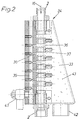
- a containment chamber 33 enclosed conveyor line section 34 installed according to Figure 2 through transverse radial slots 36 in a row Delivery line segments 37 is divided.
- Blown air channels 38 Open into the radial slots 36 Blown air channels 38, which on the opposite chamber wall of the enclosing Collection chamber 33 are aligned and of a common, parallel branch off to the delivery line section 34 extending blown air supply line 39.
- the Blown air supply line 39 has a blown air connection 41 and the collecting chamber 33 equipped with a drain port 42 for carbon particles 43.
- Filter rods 6 are conveyed from the transmitting station 1 through the pneumatic delivery line 2 to the braking means 4.
- the transverse air flow in the radial slots 36 detects free or detached carbon particles 43 or detached from the filter rods 6 and throws them in the direction of the opposite chamber wall of the collecting chamber 33, where they sink to the bottom and are removed via the outlet connection 42.
- the filter rods 6 freed from stray carbon particles 43 are gripped and braked by the belts 17a, 18a.
- a backlog of filter rods 6 forms in front of the braking means 4, a not inconsiderable pressure being exerted on the filter rod 6 held between the belts 17a, 18a.
- the filter rod 6 in question is guided practically over its entire length by the belts 17a, 18a, it can be held without slippage without being excessively deformed and braked to a defined speed.
- the guide area of the braking means 4 does not necessarily have to correspond to the entire length of a filter rod, but it can also be shorter or longer, depending on the length of the filter rods to be processed.
- the filter rods slide through the curved guide 8 and are non-positively gripped by the belts 17b, 18b of the accelerating means 7 and conveyed to the receiving station 3 in an accelerated manner. This ensures that the filter rods 6 are in each case spatially separated from a subsequent filter rod 6.
- the filter rods 6 slide over the guide surface 31 onto the guide wedge 32 and are thereby raised so that they are gripped by the belts 24 and transported upwards.
Landscapes
- Manufacturing Of Cigar And Cigarette Tobacco (AREA)
- Cigarettes, Filters, And Manufacturing Of Filters (AREA)
- Air Transport Of Granular Materials (AREA)
- Solid-Sorbent Or Filter-Aiding Compositions (AREA)
- Water Treatment By Sorption (AREA)
- Filtering Of Dispersed Particles In Gases (AREA)
Abstract
Description
Anordnungen der eingangs bezeichneten Gattung, welche mittels eines mit einer unterseitigen Öffnung versehenen, gekrümmten Leitungsabschnitts Partikel aus dem Rohrleitungssystem entfernen, sind zum Beispiel in der US-PS 5 556 236 und in der GB-PS 1 410 473 offenbart
Eine möglichst vollständige Beseitigung der am Umfang der Filterstäbe haftenden Kohlepartikel wird gemäß einer vorteilhaften Ausgestaltung dadurch erzielt, daß der Förderleitungsabschnitt durch als Radialschlitze ausgebildete Schlitze getrennte Förderleitungssegmente aufweist.
Zweckmäßigerweise zweigen die Blasluftkanäle von einer gemeinsamen, parallel zum Förderleitungsabschnitt verlaufenden Blasluftzuleitung ab.
Nach einem weiteren Vorschlag wird die Austragung der in der Auffangkammer gesammelten Partikel dadurch vereinfacht und erleichtert, daß der Förderleitungsabschnitt - bezogen auf die Förderrichtung von oben nach unten - im wesentlichen vertikal verlaufend mit einer unterseitigen Auslaßöffnung der Auffangkammer angeordnet ist.
- Figur 1
- eine Fördereinrichtung für den Transport von Filterstäben mit einer Sendestation und einer im Schnitt dargestellten Empfangsstation und
- Figur 2
- eine in die Fördereinrichtung integrierte Auffangkammer für Kohlepartikel im Schnitt.
Als Sende- und Empfangsstation können beispielsweise die von der Anmelderin unter der Bezeichnung

Das Bremsmittel 4 und das Beschleunigungsmittel 7 sind identisch in ihrem Aufbau und werden im folgenden gemeinsam beschrieben.
Die Bezugszeichen für das Bremsmittel 4 sind mit dem Index a versehen und die für das Beschleunigungsmittel 7 weisen den Index b auf. Das Bremsmittel 4 (Beschleunigungsmittel 7) besteht aus vier Rollen 11a, 12a, 13a, 14a (11b, 12b, 13b, 14b), von denen je zwei Rollen 11a, 12a (11b, 12b) bzw. 13a, 14a (13b, 14b) in Förderrichtung (Pfeil 16) der Filterstäbe 6 hintereinander angeordnet sind und von als Mittel zum Übertragen der Bremskraft (Beschleunigungskraft) auf die Filterstäbe 6 ausgebildeten endlosen Riemen 17a (17b) bzw. 18a (18b) umschlungen werden. Die Abstände der Rollen 11a und 13a (11b und 13b) bzw. 12a und 14a (12b und 14b) zueinander sind so gewählt, daß die Riemen 17a, 18a die Filterstäbe 6 einerseits fest packen, sie aber andererseits nicht zu sehr verformen. Die Rollen 11a und 13a (11b und 13b) sind über einen Riementrieb 19a (19b) und ein die Rollen 11a und 13a (11b und 13b) verbindendes Zahnradpaar 21a, 22a (21b, 22b) von einem Motor 23 antreibbar, wobei die Rollen 12a bzw. 14a (12b bzw. 14b) über die Riemen 17a (17b) bzw. 18a (18b) mit antreibbar sind. Hierbei werden die die Filterstäbe 6 fassenden Trume der Riemen 17a, 18a (17b, 18b) in Förderrichtung (Pfeil 16) der Filterstäbe 6 bewegt. Die Riementriebe 19a und 19b sind derart ausgelegt, daß die Rollen 11b und 13b des Beschleunigungsmittels 7 mit größerer Umfangsgeschwindigkeit als die Rollen 11a und 13a des Bremsmittels 4 antreibbar sind.
Die Entnahmestation 3 weist einen Förderer in Form zweier endloser paralleler Bänder 24 auf, von denen nur das hintere dargestellt ist, welche zum Bewegen der Filterstäbe 6 in queraxialer Richtung in einen nicht dargestellten Speicher, beispielsweise den Speicher einer Filteransetzmaschine, dienen. Die Förderbänder 24 sind um Walzen 26, 27 geführt, wobei die Walze 27 über ein Zahnradpaar 28 auch die entsprechende Gegenwalze über einen Zahnriemenantrieb 29 von einem nicht dargestellten Motor antreibbar sind. Eine zwischen dem Walzenpaar 26 und dem Beschleunigungsmittel 7 angeordnete Führungsfläche 31 für die aus der Förderleitung 2 austretenden Filterstäbe 6 weist einen Führungskeil 32 zum Anheben der voreilenden Enden der Filterstäbe 6 auf, so daß diese von den mittleren Trumen der paarweisen Bänder 24 erfaßt werden können.
Beim Passieren der Auffangkammer 33 im Förderleitungsabschnitt 34 erfaßt die Querluftströmung in den Radialschlitzen 36 freie bzw. aus den Filterstäben 6 herausgelöste Kohlepartikel 43 und wirft sie in Richtung der gegenüberliegenden Kammernwand der Auffangkammer 33, wo sie zu Boden sinken und über den Ablaßstutzen 42 entfernt werden.
Die von vagabundierenden Kohlepartikeln 43 befreiten Filterstäbe 6 werden von den Riemen 17a, 18a kraftschlüssig erfaßt und abgebremst. Hierdurch bildet sich vor dem Bremsmittel 4 ein Rückstau an Filterstäben 6, wobei ein nicht unerheblicher Druck auf den zwischen den Riemen 17a, 18a gehaltenen Filterstab 6 ausgeübt wird. Weil aber der betreffende Filterstab 6 praktisch über seine gesamte Länge von den Riemen 17a, 18a geführt wird, kann er, ohne daß er übermäßig verformt wird, schlupflos gehalten und auf eine definierte Geschwindigkeit abgebremst werden. Der Führungsbereich des Bremsmittels 4 muß jedoch nicht unbedingt der gesamten Länge eines Filterstabes entsprechen, sondern er kann je nach Länge der zu verarbeitenden Filterstäbe, auch kürzer oder länger sein. Nach ihrem Abbremsen rutschen die Filterstäbe durch die gekrümmte Führung 8 und werden von den Riemen 17b, 18b des Beschleunigungsmittels 7 kraftschlüssig erfaßt und beschleunigt zur Empfangsstation 3 gefördert. Hierdurch wird sichergesellt , daß die Filterstäbe 6 in jedem Fall jeweils von einem nachfolgenden Filterstab 6 räumlich getrennt werden. Die Filterstäbe 6 rutschen über die Führungsfläche 31 auf den Führungskeil 32 und werden hierbei angehoben, so daß sie von den Bändern 24 erfaßt und aufwärts transportiert werden.
Claims (4)
- Einrichtung zum Überführen von pulver- oder granulatförmige Partikeln, insbesondere Kohlepartikel, enthaltenden Filterstäben der tabakverarbeitenden Industrie von einer Sendestation zu einer Empfangsstation über eine die Artikel in längsaxialer Aufeinanderfolge transportierende pneumatische Förderleitung, mit einem freie Partikel auffangenden und ableitenden Förderleitungsabschnitt, dadurch gekennzeichnet, daß der im Bereich der Empfangsstation (3) vorgesehene Förderleitungsabschnitt (34) durch im wesentlichen querverlaufende Schlitze (36) unterbrochen ist, in welche auf eine Auffangkammer (33) ausgerichtete Blasluftkanäle (38) einmünden.
- Einrichtung nach Anspruch 1, dadurch gekennzeichnet, daß der Förderleitungsabschnitt (34) durch als Radialschlitze ausgebildete Schlitze (36) getrennte Förderleitungssegmente (37) aufweist.
- Einrichtung nach Anspruch 1 oder 2, dadurch gekennzeichnet, daß die Blasluftkanäle (38) von einer gemeinsamen, parallel zum Förderleitungsabschnitt (34) verlaufenden Blasluftzuleitung (39) abzweigen.
- Einrichtung nach einem der Ansprüche 1 bis 3, dadurch gekennzeichnet, daß der Förderleitungsabschnitt (34) - bezogen auf die Förderrichtung (Pfeil 16) von oben nach unten - im wesentlichen vertikal verlaufend mit einer unterseitigen Auslaßöffnung (42) der Auffangkammer (33) angeordnet ist.
Applications Claiming Priority (2)
| Application Number | Priority Date | Filing Date | Title |
|---|---|---|---|
| DE19913421A DE19913421A1 (de) | 1999-03-25 | 1999-03-25 | Einrichtung zum Überführen von pulver- oder granulatförmige Partikel enthaltenden Filterstäben |
| DE19913421 | 1999-03-25 |
Publications (2)
| Publication Number | Publication Date |
|---|---|
| EP1038452A1 true EP1038452A1 (de) | 2000-09-27 |
| EP1038452B1 EP1038452B1 (de) | 2003-01-08 |
Family
ID=7902287
Family Applications (1)
| Application Number | Title | Priority Date | Filing Date |
|---|---|---|---|
| EP00105161A Expired - Lifetime EP1038452B1 (de) | 1999-03-25 | 2000-03-11 | Einrichtung zum Überführen von pulver- oder granulatförmige Artikel enthaltenden Filterstäben |
Country Status (8)
| Country | Link |
|---|---|
| US (2) | US6415474B1 (de) |
| EP (1) | EP1038452B1 (de) |
| JP (1) | JP2000300238A (de) |
| CN (1) | CN1121827C (de) |
| AT (1) | ATE230570T1 (de) |
| DE (2) | DE19913421A1 (de) |
| ES (1) | ES2187404T3 (de) |
| PL (1) | PL193877B1 (de) |
Cited By (2)
| Publication number | Priority date | Publication date | Assignee | Title |
|---|---|---|---|---|
| EP2742812A1 (de) * | 2012-12-12 | 2014-06-18 | HAUNI Maschinenbau AG | Vorrichtung und Verfahren zum Auffangen und Ableiten freier, beim Fördern stabförmiger Artikel der Tabak verarbeitenden Industrie anfallender Partikel |
| EP3228197A1 (de) * | 2016-04-05 | 2017-10-11 | Hauni Maschinenbau GmbH | Empfangsvorrichtung und förderverfahren der tabak verarbeitenden industrie |
Families Citing this family (9)
| Publication number | Priority date | Publication date | Assignee | Title |
|---|---|---|---|---|
| NL1012806C2 (nl) * | 1999-08-11 | 2001-02-13 | Peinemann Equipment Bv | Aandrijfinrichting voor flexibele lans. |
| US6511549B1 (en) * | 2001-08-17 | 2003-01-28 | Philp Morris Incorporated | Vacuum cleaning wheel and vacuum applicator |
| US20030203384A1 (en) * | 2002-03-08 | 2003-10-30 | Chafin David R. | Multiplex detection of biological materials in a sample |
| EP1397966A1 (de) * | 2002-09-11 | 2004-03-17 | Hauni Maschinenbau AG | Vorrichtung und Verfahren zur Förderung von stabförmigen Filterelementen |
| KR100529869B1 (ko) * | 2003-10-01 | 2005-11-22 | 주식회사 엘지화학 | 리튬 이온 폴리머 전지팩 구조 |
| US7207527B2 (en) * | 2003-04-14 | 2007-04-24 | Klo-Shure, Inc. | Clevis hanger assembly and pipe insulation coupling |
| CN104534214B (zh) * | 2014-12-10 | 2016-06-01 | 河南中烟工业有限责任公司 | 一种烟草周转箱底部自清洁压缩空气自动对接装置 |
| EP3735844B1 (de) | 2019-05-10 | 2025-03-19 | Körber Technologies GmbH | Einrichtung zum überführen von stabförmigen artikeln der tabak verarbeitenden industrie |
| CN113979132B (zh) * | 2021-11-17 | 2023-06-30 | 浙江中烟工业有限责任公司 | 一种风力送丝烟丝管道状态智能诊断系统及方法 |
Citations (3)
| Publication number | Priority date | Publication date | Assignee | Title |
|---|---|---|---|---|
| GB1410473A (en) | 1971-12-10 | 1975-10-15 | Hauni Werke Koerber & Co Kg | Delivery apparatus for rodlike articles of the tobacco-processing industry |
| EP0699396A2 (de) * | 1994-09-02 | 1996-03-06 | Hauni Maschinenbau Aktiengesellschaft | Vorrichtung zum Fördern von Filterstäben |
| US5556236A (en) | 1992-11-11 | 1996-09-17 | Molins Plc | Conveyor system for rod-like articles |
Family Cites Families (6)
| Publication number | Priority date | Publication date | Assignee | Title |
|---|---|---|---|---|
| US1575526A (en) * | 1926-03-02 | Xabl bochbb | ||
| US2367393A (en) * | 1939-12-30 | 1945-01-16 | Armstrong Cork Co | Closure cleaning device |
| US3909873A (en) * | 1973-08-15 | 1975-10-07 | Alexandr Nikolaevich Minasov | Device for dedusting loose materials |
| US4073029A (en) * | 1976-05-27 | 1978-02-14 | Vassallo Alphonse C | Parts cleaner |
| US4167797A (en) * | 1977-11-11 | 1979-09-18 | H-C Industries, Inc. | Closure cleaning machine |
| DE4008475C2 (de) | 1990-03-16 | 2002-10-10 | Hauni Werke Koerber & Co Kg | Verfahren und Vorrichtung zum Herstellen von Filterzigaretten |
-
1999
- 1999-03-25 DE DE19913421A patent/DE19913421A1/de not_active Withdrawn
-
2000
- 2000-03-11 EP EP00105161A patent/EP1038452B1/de not_active Expired - Lifetime
- 2000-03-11 DE DE50001028T patent/DE50001028D1/de not_active Expired - Fee Related
- 2000-03-11 AT AT00105161T patent/ATE230570T1/de not_active IP Right Cessation
- 2000-03-11 ES ES00105161T patent/ES2187404T3/es not_active Expired - Lifetime
- 2000-03-22 PL PL339165A patent/PL193877B1/pl not_active IP Right Cessation
- 2000-03-24 JP JP2000084780A patent/JP2000300238A/ja not_active Withdrawn
- 2000-03-25 CN CN00107045A patent/CN1121827C/zh not_active Expired - Fee Related
- 2000-03-27 US US09/534,570 patent/US6415474B1/en not_active Expired - Fee Related
-
2002
- 2002-02-20 US US10/078,227 patent/US6596090B2/en not_active Expired - Fee Related
Patent Citations (3)
| Publication number | Priority date | Publication date | Assignee | Title |
|---|---|---|---|---|
| GB1410473A (en) | 1971-12-10 | 1975-10-15 | Hauni Werke Koerber & Co Kg | Delivery apparatus for rodlike articles of the tobacco-processing industry |
| US5556236A (en) | 1992-11-11 | 1996-09-17 | Molins Plc | Conveyor system for rod-like articles |
| EP0699396A2 (de) * | 1994-09-02 | 1996-03-06 | Hauni Maschinenbau Aktiengesellschaft | Vorrichtung zum Fördern von Filterstäben |
Cited By (3)
| Publication number | Priority date | Publication date | Assignee | Title |
|---|---|---|---|---|
| EP2742812A1 (de) * | 2012-12-12 | 2014-06-18 | HAUNI Maschinenbau AG | Vorrichtung und Verfahren zum Auffangen und Ableiten freier, beim Fördern stabförmiger Artikel der Tabak verarbeitenden Industrie anfallender Partikel |
| EP3415017A1 (de) * | 2012-12-12 | 2018-12-19 | Hauni Maschinenbau GmbH | Vorrichtung und verfahren zum auffangen und ableiten freier, beim fördern stabförmiger artikel der tabak verarbeitenden industrie anfallender partikel |
| EP3228197A1 (de) * | 2016-04-05 | 2017-10-11 | Hauni Maschinenbau GmbH | Empfangsvorrichtung und förderverfahren der tabak verarbeitenden industrie |
Also Published As
| Publication number | Publication date |
|---|---|
| DE50001028D1 (de) | 2003-02-13 |
| CN1121827C (zh) | 2003-09-24 |
| US20020088479A1 (en) | 2002-07-11 |
| US6596090B2 (en) | 2003-07-22 |
| CN1269993A (zh) | 2000-10-18 |
| ATE230570T1 (de) | 2003-01-15 |
| DE19913421A1 (de) | 2000-09-28 |
| PL339165A1 (en) | 2000-10-09 |
| US6415474B1 (en) | 2002-07-09 |
| ES2187404T3 (es) | 2003-06-16 |
| JP2000300238A (ja) | 2000-10-31 |
| EP1038452B1 (de) | 2003-01-08 |
| PL193877B1 (pl) | 2007-03-30 |
Similar Documents
| Publication | Publication Date | Title |
|---|---|---|
| DE3026001C2 (de) | ||
| EP1038452B1 (de) | Einrichtung zum Überführen von pulver- oder granulatförmige Artikel enthaltenden Filterstäben | |
| DE202008009166U1 (de) | Transportvorrichtung zum Zuführen von Artikeln zu einer Verpackungsmaschine | |
| EP2005848B1 (de) | Empfangsvorrichtung und Förderverfahren | |
| DE102012208385A1 (de) | Vorrichtung zum Entleeren eines mit Stückgut beladenen Ladungsträgers | |
| DE2634250B2 (de) | Verfahren und Vorrichtung zum Beschicken einer Karde mit Fasermaterial | |
| DE69511959T2 (de) | Verfahren und Einrichtung zur Umsetzung einer Schicht von stabförmigen Gegenständen in einen Massenstrom | |
| EP1038453B1 (de) | Einrichtung zum Überführen von pulver- oder granulatförmige Artikel enthaltenden Filterstäben | |
| EP2545790A1 (de) | Zigarettenzerlegevorrichtung für Filterzigaretten und Zigarettenzerlegemaschine und Verfahren zur Zerlegung einer Filterzigarette | |
| EP1062883A1 (de) | Verfahren und Vorrichtung zum Herstellen und/oder Verpacken von Zigaretten | |
| DE102007049780A1 (de) | Verfahren und Vorrichtung zum kontrollierten Übergeben von Stückgütern | |
| DE2363505A1 (de) | Aufgabevorrichtung einer druckluftfoerderanlage fuer schuettgut | |
| DE2306096A1 (de) | Bremsmittel in einer pneumatischen foerderleitung fuer filterstaebe | |
| DE2254230C2 (de) | Vorrichtung zum Ändern der Förderrichtung von längsaxial geförderten Filterstäben | |
| DE69918525T2 (de) | Vorrichtung zum kontinuierlichen Zuführen von Korken | |
| EP3733314B1 (de) | Ausschleusevorrichtung | |
| DE102016101602A1 (de) | Vorrichtung und Verfahren zum Abblasen von Behältern, insbesondere von Flaschen oder Dosen | |
| EP3015003B1 (de) | Sortiervorrichtung für längliche Artikel, insbesondere für Zigaretten | |
| EP3735844B1 (de) | Einrichtung zum überführen von stabförmigen artikeln der tabak verarbeitenden industrie | |
| DE10145848A1 (de) | Vereinzelungsvorrichtung für Dosen | |
| DE3318797A1 (de) | Zellenradschleuse | |
| DE1461929B1 (de) | Vorrichtung zum Zufuehren von Schokoladetafeln oder -Riegeln zu einer Einwickelmaschine | |
| CH294201A (de) | Vorrichtung zum Sortieren und Reinigen von Massengut, wie Getreide, Hülsenfrüchte, Müllereiprodukte und dergleichen, beim pneumatischen Transport desselben. | |
| DE10002753A1 (de) | Pneumatische Fördereinrichtung zum Überführen stabförmiger Artikel der Tabak verarbeitenden Industrie | |
| DE3903130A1 (de) | Verfahren und vorrichtungen zum aufbereiten von blumenzwiebeln |
Legal Events
| Date | Code | Title | Description |
|---|---|---|---|
| PUAI | Public reference made under article 153(3) epc to a published international application that has entered the european phase |
Free format text: ORIGINAL CODE: 0009012 |
|
| AK | Designated contracting states |
Kind code of ref document: A1 Designated state(s): AT BE CH CY DE DK ES FI FR GB GR IE IT LI LU MC NL PT SE |
|
| AX | Request for extension of the european patent |
Free format text: AL;LT;LV;MK;RO;SI |
|
| 17P | Request for examination filed |
Effective date: 20010310 |
|
| AKX | Designation fees paid |
Free format text: AT BE CH CY DE DK ES FI FR GB GR IE IT LI LU MC NL PT SE |
|
| GRAH | Despatch of communication of intention to grant a patent |
Free format text: ORIGINAL CODE: EPIDOS IGRA |
|
| GRAH | Despatch of communication of intention to grant a patent |
Free format text: ORIGINAL CODE: EPIDOS IGRA |
|
| GRAA | (expected) grant |
Free format text: ORIGINAL CODE: 0009210 |
|
| RIN1 | Information on inventor provided before grant (corrected) |
Inventor name: SCHMIDT, HANS-HERBERT |
|
| AK | Designated contracting states |
Kind code of ref document: B1 Designated state(s): AT BE CH CY DE DK ES FI FR GB GR IE IT LI LU MC NL PT SE |
|
| PG25 | Lapsed in a contracting state [announced via postgrant information from national office to epo] |
Ref country code: GR Free format text: LAPSE BECAUSE OF FAILURE TO SUBMIT A TRANSLATION OF THE DESCRIPTION OR TO PAY THE FEE WITHIN THE PRESCRIBED TIME-LIMIT Effective date: 20030108 Ref country code: IE Free format text: LAPSE BECAUSE OF FAILURE TO SUBMIT A TRANSLATION OF THE DESCRIPTION OR TO PAY THE FEE WITHIN THE PRESCRIBED TIME-LIMIT Effective date: 20030108 Ref country code: FI Free format text: LAPSE BECAUSE OF FAILURE TO SUBMIT A TRANSLATION OF THE DESCRIPTION OR TO PAY THE FEE WITHIN THE PRESCRIBED TIME-LIMIT Effective date: 20030108 |
|
| REF | Corresponds to: |
Ref document number: 230570 Country of ref document: AT Date of ref document: 20030115 Kind code of ref document: T |
|
| REG | Reference to a national code |
Ref country code: GB Ref legal event code: FG4D Free format text: NOT ENGLISH |
|
| REG | Reference to a national code |
Ref country code: CH Ref legal event code: EP |
|
| GBT | Gb: translation of ep patent filed (gb section 77(6)(a)/1977) |
Effective date: 20030108 |
|
| REG | Reference to a national code |
Ref country code: IE Ref legal event code: FG4D Free format text: GERMAN |
|
| REF | Corresponds to: |
Ref document number: 50001028 Country of ref document: DE Date of ref document: 20030213 Kind code of ref document: P |
|
| PG25 | Lapsed in a contracting state [announced via postgrant information from national office to epo] |
Ref country code: LU Free format text: LAPSE BECAUSE OF NON-PAYMENT OF DUE FEES Effective date: 20030311 Ref country code: AT Free format text: LAPSE BECAUSE OF NON-PAYMENT OF DUE FEES Effective date: 20030311 Ref country code: CY Free format text: LAPSE BECAUSE OF FAILURE TO SUBMIT A TRANSLATION OF THE DESCRIPTION OR TO PAY THE FEE WITHIN THE PRESCRIBED TIME-LIMIT Effective date: 20030311 |
|
| PG25 | Lapsed in a contracting state [announced via postgrant information from national office to epo] |
Ref country code: MC Free format text: LAPSE BECAUSE OF NON-PAYMENT OF DUE FEES Effective date: 20030331 Ref country code: BE Free format text: LAPSE BECAUSE OF NON-PAYMENT OF DUE FEES Effective date: 20030331 |
|
| PG25 | Lapsed in a contracting state [announced via postgrant information from national office to epo] |
Ref country code: SE Free format text: LAPSE BECAUSE OF FAILURE TO SUBMIT A TRANSLATION OF THE DESCRIPTION OR TO PAY THE FEE WITHIN THE PRESCRIBED TIME-LIMIT Effective date: 20030408 Ref country code: PT Free format text: LAPSE BECAUSE OF FAILURE TO SUBMIT A TRANSLATION OF THE DESCRIPTION OR TO PAY THE FEE WITHIN THE PRESCRIBED TIME-LIMIT Effective date: 20030408 Ref country code: DK Free format text: LAPSE BECAUSE OF FAILURE TO SUBMIT A TRANSLATION OF THE DESCRIPTION OR TO PAY THE FEE WITHIN THE PRESCRIBED TIME-LIMIT Effective date: 20030408 |
|
| REG | Reference to a national code |
Ref country code: ES Ref legal event code: FG2A Ref document number: 2187404 Country of ref document: ES Kind code of ref document: T3 |
|
| ET | Fr: translation filed | ||
| REG | Reference to a national code |
Ref country code: IE Ref legal event code: FD4D Ref document number: 1038452E Country of ref document: IE |
|
| BERE | Be: lapsed |
Owner name: *HAUNI MASCHINENBAU A.G. Effective date: 20030331 |
|
| PLBE | No opposition filed within time limit |
Free format text: ORIGINAL CODE: 0009261 |
|
| STAA | Information on the status of an ep patent application or granted ep patent |
Free format text: STATUS: NO OPPOSITION FILED WITHIN TIME LIMIT |
|
| 26N | No opposition filed |
Effective date: 20031009 |
|
| PGFP | Annual fee paid to national office [announced via postgrant information from national office to epo] |
Ref country code: ES Payment date: 20040216 Year of fee payment: 5 |
|
| PGFP | Annual fee paid to national office [announced via postgrant information from national office to epo] |
Ref country code: FR Payment date: 20040322 Year of fee payment: 5 |
|
| PGFP | Annual fee paid to national office [announced via postgrant information from national office to epo] |
Ref country code: CH Payment date: 20040326 Year of fee payment: 5 |
|
| PG25 | Lapsed in a contracting state [announced via postgrant information from national office to epo] |
Ref country code: ES Free format text: LAPSE BECAUSE OF NON-PAYMENT OF DUE FEES Effective date: 20050312 |
|
| PG25 | Lapsed in a contracting state [announced via postgrant information from national office to epo] |
Ref country code: CH Free format text: LAPSE BECAUSE OF NON-PAYMENT OF DUE FEES Effective date: 20050331 Ref country code: LI Free format text: LAPSE BECAUSE OF NON-PAYMENT OF DUE FEES Effective date: 20050331 |
|
| REG | Reference to a national code |
Ref country code: CH Ref legal event code: PL |
|
| PG25 | Lapsed in a contracting state [announced via postgrant information from national office to epo] |
Ref country code: FR Free format text: LAPSE BECAUSE OF NON-PAYMENT OF DUE FEES Effective date: 20051130 |
|
| REG | Reference to a national code |
Ref country code: FR Ref legal event code: ST Effective date: 20051130 |
|
| PGFP | Annual fee paid to national office [announced via postgrant information from national office to epo] |
Ref country code: IT Payment date: 20060331 Year of fee payment: 7 |
|
| REG | Reference to a national code |
Ref country code: ES Ref legal event code: FD2A Effective date: 20050312 |
|
| PGFP | Annual fee paid to national office [announced via postgrant information from national office to epo] |
Ref country code: GB Payment date: 20070220 Year of fee payment: 8 |
|
| PGFP | Annual fee paid to national office [announced via postgrant information from national office to epo] |
Ref country code: DE Payment date: 20070326 Year of fee payment: 8 |
|
| PGFP | Annual fee paid to national office [announced via postgrant information from national office to epo] |
Ref country code: NL Payment date: 20070327 Year of fee payment: 8 |
|
| GBPC | Gb: european patent ceased through non-payment of renewal fee |
Effective date: 20080311 |
|
| PG25 | Lapsed in a contracting state [announced via postgrant information from national office to epo] |
Ref country code: NL Free format text: LAPSE BECAUSE OF NON-PAYMENT OF DUE FEES Effective date: 20081001 |
|
| NLV4 | Nl: lapsed or anulled due to non-payment of the annual fee |
Effective date: 20081001 |
|
| PG25 | Lapsed in a contracting state [announced via postgrant information from national office to epo] |
Ref country code: DE Free format text: LAPSE BECAUSE OF NON-PAYMENT OF DUE FEES Effective date: 20081001 |
|
| PG25 | Lapsed in a contracting state [announced via postgrant information from national office to epo] |
Ref country code: GB Free format text: LAPSE BECAUSE OF NON-PAYMENT OF DUE FEES Effective date: 20080311 |
|
| PG25 | Lapsed in a contracting state [announced via postgrant information from national office to epo] |
Ref country code: IT Free format text: LAPSE BECAUSE OF NON-PAYMENT OF DUE FEES Effective date: 20070311 |