EP1037310A2 - Hülsenförmiges Klemmelement zum abisolierfreien Anschluss elektrischer Leiter - Google Patents
Hülsenförmiges Klemmelement zum abisolierfreien Anschluss elektrischer Leiter Download PDFInfo
- Publication number
- EP1037310A2 EP1037310A2 EP00101409A EP00101409A EP1037310A2 EP 1037310 A2 EP1037310 A2 EP 1037310A2 EP 00101409 A EP00101409 A EP 00101409A EP 00101409 A EP00101409 A EP 00101409A EP 1037310 A2 EP1037310 A2 EP 1037310A2
- Authority
- EP
- European Patent Office
- Prior art keywords
- cross
- clamping element
- clamping
- section
- sleeve body
- Prior art date
- Legal status (The legal status is an assumption and is not a legal conclusion. Google has not performed a legal analysis and makes no representation as to the accuracy of the status listed.)
- Granted
Links
- 239000004020 conductor Substances 0.000 title claims description 7
- 238000005452 bending Methods 0.000 description 4
- 239000000463 material Substances 0.000 description 3
- 239000002184 metal Substances 0.000 description 2
- 230000000694 effects Effects 0.000 description 1
- 238000005516 engineering process Methods 0.000 description 1
- 230000001771 impaired effect Effects 0.000 description 1
- 239000012774 insulation material Substances 0.000 description 1
- 239000007769 metal material Substances 0.000 description 1
- 230000003716 rejuvenation Effects 0.000 description 1
- 230000007704 transition Effects 0.000 description 1
Images
Classifications
-
- H—ELECTRICITY
- H01—ELECTRIC ELEMENTS
- H01R—ELECTRICALLY-CONDUCTIVE CONNECTIONS; STRUCTURAL ASSOCIATIONS OF A PLURALITY OF MUTUALLY-INSULATED ELECTRICAL CONNECTING ELEMENTS; COUPLING DEVICES; CURRENT COLLECTORS
- H01R4/00—Electrically-conductive connections between two or more conductive members in direct contact, i.e. touching one another; Means for effecting or maintaining such contact; Electrically-conductive connections having two or more spaced connecting locations for conductors and using contact members penetrating insulation
- H01R4/24—Connections using contact members penetrating or cutting insulation or cable strands
- H01R4/2416—Connections using contact members penetrating or cutting insulation or cable strands the contact members having insulation-cutting edges, e.g. of tuning fork type
- H01R4/2445—Connections using contact members penetrating or cutting insulation or cable strands the contact members having insulation-cutting edges, e.g. of tuning fork type the contact members having additional means acting on the insulation or the wire, e.g. additional insulation penetrating means, strain relief means or wire cutting knives
- H01R4/2458—Connections using contact members penetrating or cutting insulation or cable strands the contact members having insulation-cutting edges, e.g. of tuning fork type the contact members having additional means acting on the insulation or the wire, e.g. additional insulation penetrating means, strain relief means or wire cutting knives the contact members being in a slotted tubular configuration, e.g. slotted tube-end
Definitions
- the invention relates to a sleeve-shaped clamping element the specified in the preamble of claim 1 Art.
- Such clamping elements are from DE-Ausschschrift 23 39th 800 and known from DE Patent 32 39 708.
- the in trained in its entirety as a metal clamping spring Sleeve body of such clamping elements has over its entire Cross-section a constant thickness, which is the case with both Contact, namely when cutting into the insulating jacket of the head concerned, as well as regarding the Space requirement of the clamping element in the associated terminal housing is disadvantageous.
- It is with respect to the mechanical stress curve with applied clamping forces of the flared sleeve body does not require him to the same thickness up to the clamping slot. Rather, it should be based on the elastically deformable area, in which the stresses when the sleeve body is jammed according to the length of the lever arm from the clamping point seen increase with constant material thickness, which is by no means cheap.
- the invention is therefore based on the object, a sleeve-shaped Clamping element of the generic type create its design taking into account the bending stress curve is optimized in the clamped state.
- the material rejuvenation has an effect of the clamping leg on the clamping slot itself due to a lower material thickness in the cutting area of the Clamping leg out, which means that when the non-stripped electrical conductor into the clamping slot the cutting of the insulating jacket of the conductor favors becomes.
- the constant miniaturization of the building blocks for the terminal technology in cross-section tapered clamping leg space advantages because it is given the available space further away from the clamping slot can expand or when space is limited Head can contact unchanged cross section without that the cutting and clamping forces are impaired.
- the sleeve-shaped clamping element according to the invention the usual has a symmetrical design with two clamping legs, both of them are designed with a tapering cross-section. You get there so a uniform course of the mechanical tension in the clamping legs, the bending range of which is extended can be, whereby higher restoring forces are possible.
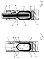
- terminal housing 1 shows a terminal housing 1, in which there is a terminal space 2, which is perpendicular to the plane of representation extends. In it there is one with his Arranged in the same direction extending sleeve body 3, that of a metal with suitable spring properties exists and at least electrically with a busbar 7 is connected.
- the sleeve body 3 represents a clamping element, which a clamping slot 4 along its upper apex region having. Through this clamping slot 4 one goes through one dash-dotted line indicated plane through to the entire sleeve body 3 is mirror-symmetrical is.
- the sleeve body 3 has seen in cross section a box profile or a U-profile, the U-legs form two opposing clamping legs 5, which are integrally connected to one another via the lower U-web 6 are.
- the U-web 6 is fixed, in particular electrically conductively connected to the busbar 7.
- the U-web 6 goes over rounded arches 8 in the spring legs 5 over that run up to bends 9, of which from them converging towards each other, sloping roof extending leg ends 10, which end with Cut 11 limit the clamping slot 4.
- the peculiarity of the sleeve body 3 is that the Clamp leg 5 upwards, that is towards the clamping slot 4 taper in cross-section.
- the tapered area extends between the rounded arches 8 at the transition to the U-bridge 6 and the upper bends 9 so that the leg ends 10 from the bends 9 to the clamping slot 4 or their cutting edges 11 a substantially constant Cross section.
- the electrical conductor is inserted 12 the sleeve body 3 expanded, i.e. its elastic Clamping legs 5 now have outer sides lying parallel to one another, up to their position on the clamping slot 4 between the blades 11 have a larger spring or clamping path of the two clamping legs 5 is available. Also recognizes here that the ends 10 the clamping leg 5 more easily into the insulation material 13 of the conductor 12 can penetrate.
Landscapes
- Clamps And Clips (AREA)
- Details Of Connecting Devices For Male And Female Coupling (AREA)
- Suspension Of Electric Lines Or Cables (AREA)
Abstract
Description
- Fig. 1
- den Querschnitt durch eine Klemme mit einem hülsenförmigen Klemmelement entsprechend der Erfindung und
- Fig. 2
- eine der Figur 1 entsprechende Darstellung, jedoch mit in die Klemme eingeführtem, elektrischem Leiter.
Claims (7)
- Hülsenförmiges Klemmelement mit einem dem abisolierfreien Anschluß eines elektrischen Leiters dienenden und in Längsrichtung des Hülsenkörpers verlaufenden Klemmschlitz, wobei der Hülsenkörper im Querschnitt gesehen zwei miteinander einstückige, einander gegenüberliegende sowie im Bereich zum Klemmschlitz hin konvergierende Federschenkel mit den Klemmschlitz begrenzenden Schneiden aufweist,
dadurch gekennzeichnet,
daß sich zumindest einer der beiden Federschenkel (5) in seinem elastisch verformbaren Bereich in Richtung zum Klemmschlitz (4) hin in seinem Querschnitt verjüngt. - Klemmelement nach Anspruch 1,
dadurch gekennzeichnet,
daß der verjüngte Querschnitt bis zur Schneide (11) des Federschenkels (5) reicht. - Klemmelement nach Anspruch 1 oder 2,
dadurch gekennzeichnet,
daß die Querschnittsabnahme des Federschenkles (5) stetig ist. - Klemmelement nach einem der Ansprüche 1 bis 3,
dadurch gekennzeichnet,
daß beide Federschenkel (5) bezogen auf eine durch den Klemmschlitz (4) hindurchgehende Ebene spiegelsymmetrich und beide mit der Querschnittsverjüngung ausgebildet sind. - Klemmelement nach Anspruch 4,
dadurch gekennzeichnet,
daß der Hülsenkörper (3) im Querschnitt U-förmig ist, wobei die U-Schenkel die Federschenkel (5) bilden und gegeneinander abgewinkelte Enden (10) haben. - Klemmelement nach Anspruch 4,
dadurch gekennzeichnet,
daß die abgewinkelten Enden (10) der Federschenkel (5) bezogen auf den Gesamtquerschnitt des Hülsenkörpers (3) dachschrägenförmig angeordnet sind. - Klemmelement nach Anspruch 5 oder 6,
dadurch gekennzeichnet, daß der U-Steg (6) des Hülsenkörpers (3) eine konstante Dicke hat und mittels gerundeter Bögen (8) in die Federschenkel (5) übergeht, die sich von dem jeweils zugehörigen Bogen (8) bis hin zur Abwinklung (9) ihrer Enden (10) verjüngen.
Applications Claiming Priority (2)
| Application Number | Priority Date | Filing Date | Title |
|---|---|---|---|
| DE19909825 | 1999-03-05 | ||
| DE1999109825 DE19909825C5 (de) | 1999-03-05 | 1999-03-05 | Hülsenförmiges Klemmelement zum abisolierfreien Anschluß elektrischer Leiter |
Publications (4)
| Publication Number | Publication Date |
|---|---|
| EP1037310A2 true EP1037310A2 (de) | 2000-09-20 |
| EP1037310A3 EP1037310A3 (de) | 2001-08-08 |
| EP1037310B1 EP1037310B1 (de) | 2005-11-16 |
| EP1037310B3 EP1037310B3 (de) | 2014-09-17 |
Family
ID=7899889
Family Applications (1)
| Application Number | Title | Priority Date | Filing Date |
|---|---|---|---|
| EP20000101409 Expired - Lifetime EP1037310B3 (de) | 1999-03-05 | 2000-01-25 | Hülsenförmiges Klemmelement zum abisolierfreien Anschluss elektrischer Leiter |
Country Status (2)
| Country | Link |
|---|---|
| EP (1) | EP1037310B3 (de) |
| DE (2) | DE19909825C5 (de) |
Families Citing this family (4)
| Publication number | Priority date | Publication date | Assignee | Title |
|---|---|---|---|---|
| DE20313285U1 (de) * | 2003-08-27 | 2004-09-30 | Weco Wester, Ebbinghaus Gmbh & Co. Kg | Elektrische Anschlussklemme |
| DE102004047148B4 (de) * | 2004-09-29 | 2006-10-12 | Lic Langmatz Gmbh | Elektrische Klemme sowie Kabelübergangs- und Sicherungskasten mit derartigen Klemmen |
| DE102007046616B4 (de) | 2007-09-27 | 2011-04-14 | Wago Verwaltungsgesellschaft Mbh | Schneidklemmanschluss |
| CH699105A1 (de) | 2008-07-11 | 2010-01-15 | Reichle & De Massari Fa | Schneidklemmkontakt und Kontaktierungsvorrichtung. |
Family Cites Families (5)
| Publication number | Priority date | Publication date | Assignee | Title |
|---|---|---|---|---|
| DE2339800C2 (de) * | 1973-08-06 | 1975-01-09 | Siemens Ag, 1000 Berlin Und 8000 Muenchen | Hülsenförmiges Klemmelement zum abisolierfreien Anschluß elektrischer Leiter |
| US3960431A (en) * | 1975-07-21 | 1976-06-01 | Nothern Electric Company Limited | Electrical connector |
| FR2503464A1 (fr) * | 1981-04-03 | 1982-10-08 | Alsthom Cgee | Bloc de jonction a raccordement electrique sans denudage |
| DE3781997T2 (de) * | 1986-10-10 | 1993-02-18 | Entrelec Sa | Geschlitzte anschlusseinrichtung fuer elektrisches kabel und dementsprechendes anschlusswerkzeug. |
| FR2722033B1 (fr) * | 1994-07-04 | 1996-08-02 | Entrelec Sa | Module de raccordement electrique a piece de connexion du type a fente de retenue de fil dotee d'une embouchure denudante |
-
1999
- 1999-03-05 DE DE1999109825 patent/DE19909825C5/de not_active Expired - Lifetime
-
2000
- 2000-01-25 EP EP20000101409 patent/EP1037310B3/de not_active Expired - Lifetime
- 2000-01-25 DE DE50011598T patent/DE50011598D1/de not_active Expired - Lifetime
Also Published As
| Publication number | Publication date |
|---|---|
| DE19909825C5 (de) | 2006-01-26 |
| DE50011598D1 (de) | 2005-12-22 |
| DE19909825C2 (de) | 2001-05-31 |
| EP1037310B3 (de) | 2014-09-17 |
| EP1037310A3 (de) | 2001-08-08 |
| DE19909825A1 (de) | 2000-09-21 |
| EP1037310B1 (de) | 2005-11-16 |
Similar Documents
| Publication | Publication Date | Title |
|---|---|---|
| EP2917971B1 (de) | Federkraftklemmanschluss und elektrisches gerät hiermit | |
| EP3507866B1 (de) | Leiteranschlussklemme | |
| EP2956993B1 (de) | Federklemmkontakt und verbindungsklemme für elektrische leiter | |
| DE102013101411B4 (de) | Federkraftklemmanschluss und Leiteranschlussklemme | |
| DE19641206C2 (de) | Anschlußklemme für elektrische Leiter | |
| DE19711051B4 (de) | Elektrische Klemme | |
| DE8816798U1 (de) | Stiftförmiges Kontaktelement zur Befestigung in Leiterplattenbohrungen | |
| EP3292591B1 (de) | Leiteranschlussklemme | |
| DE102007046616A1 (de) | Schneidklemmanschluss | |
| DE3818497C5 (de) | Anschlußblock für eine Kabelabschlußeinheit | |
| DE2922477A1 (de) | Reihenklemme mit schraubenloser klemmung | |
| EP1008205B1 (de) | Reihenklemme zum abisolierungsfreien anschluss isolierter leiter | |
| EP2692027A2 (de) | Querbrücker für eine elektrische klemme | |
| EP1037310B1 (de) | Hülsenförmiges Klemmelement zum abisolierfreien Anschluss elektrischer Leiter | |
| DE3340341C2 (de) | ||
| DE3118057C2 (de) | Anschlußklemme für elektrische Leiter | |
| DE19741136C2 (de) | Elektrische Anschluß- oder Verbindungsklemme | |
| DE102011054425A1 (de) | Federkörper einer Federkraftklemme und Federkraftklemmanordnung | |
| DE10111190B4 (de) | Anschlussklemme mit Kontaktstück | |
| EP0336251B1 (de) | Schraubklemme | |
| EP3855572A1 (de) | Verbindungsklemme | |
| DE19851956C2 (de) | Schneid-Klemmkontakt | |
| DE102011054418B4 (de) | Federkörper einer Federkraftklemme und Federkraftklemmanordnung | |
| DE202020005444U1 (de) | Anschlussklemme | |
| DE10158585C1 (de) | Anschlussklemme |
Legal Events
| Date | Code | Title | Description |
|---|---|---|---|
| PUAI | Public reference made under article 153(3) epc to a published international application that has entered the european phase |
Free format text: ORIGINAL CODE: 0009012 |
|
| AK | Designated contracting states |
Kind code of ref document: A2 Designated state(s): DE FR IT |
|
| AX | Request for extension of the european patent |
Free format text: AL;LT;LV;MK;RO;SI |
|
| PUAL | Search report despatched |
Free format text: ORIGINAL CODE: 0009013 |
|
| AK | Designated contracting states |
Kind code of ref document: A3 Designated state(s): AT BE CH CY DE DK ES FI FR GB GR IE IT LI LU MC NL PT SE |
|
| AX | Request for extension of the european patent |
Free format text: AL;LT;LV;MK;RO;SI |
|
| 17P | Request for examination filed |
Effective date: 20010718 |
|
| AKX | Designation fees paid |
Free format text: DE FR IT |
|
| RAP1 | Party data changed (applicant data changed or rights of an application transferred) |
Owner name: PHOENIX CONTACT GMBH & CO. KG |
|
| GRAP | Despatch of communication of intention to grant a patent |
Free format text: ORIGINAL CODE: EPIDOSNIGR1 |
|
| GRAS | Grant fee paid |
Free format text: ORIGINAL CODE: EPIDOSNIGR3 |
|
| GRAA | (expected) grant |
Free format text: ORIGINAL CODE: 0009210 |
|
| AK | Designated contracting states |
Kind code of ref document: B1 Designated state(s): DE FR IT |
|
| REF | Corresponds to: |
Ref document number: 50011598 Country of ref document: DE Date of ref document: 20051222 Kind code of ref document: P |
|
| ET | Fr: translation filed | ||
| PLBE | No opposition filed within time limit |
Free format text: ORIGINAL CODE: 0009261 |
|
| 26N | No opposition filed |
Effective date: 20060817 |
|
| REG | Reference to a national code |
Ref country code: DE Ref legal event code: R055 Ref document number: 50011598 Country of ref document: DE |
|
| PLCP | Request for limitation filed |
Free format text: ORIGINAL CODE: EPIDOSNLIM1 |
|
| PLCQ | Request for limitation of patent found admissible |
Free format text: ORIGINAL CODE: 0009231 |
|
| PLCR | Communication despatched that request for limitation of patent was allowed |
Free format text: ORIGINAL CODE: 0009245 |
|
| REG | Reference to a national code |
Ref country code: DE Ref legal event code: R097 Ref document number: 50011598 Country of ref document: DE |
|
| LIM1 | Request for limitation found admissible |
Free format text: SEQUENCE NO: 1; FILED AFTER OPPOSITION PERIOD Filing date: 20130425 Effective date: 20130425 |
|
| PLCN | Payment of fee for limitation of patent |
Free format text: ORIGINAL CODE: EPIDOSNRAL3 |
|
| PUAM | (expected) publication of b3 document |
Free format text: ORIGINAL CODE: 0009410 |
|
| REG | Reference to a national code |
Ref country code: DE Ref legal event code: R056 Ref document number: 50011598 Country of ref document: DE Effective date: 20130712 |
|
| PLCP | Request for limitation filed |
Free format text: ORIGINAL CODE: EPIDOSNLIM1 |
|
| PLCQ | Request for limitation of patent found admissible |
Free format text: ORIGINAL CODE: 0009231 |
|
| PLCH | Information related to payment of fee for limitation of patent deleted |
Free format text: ORIGINAL CODE: EPIDOSDRAL3 |
|
| PLCN | Payment of fee for limitation of patent |
Free format text: ORIGINAL CODE: EPIDOSNRAL3 |
|
| PLCR | Communication despatched that request for limitation of patent was allowed |
Free format text: ORIGINAL CODE: 0009245 |
|
| LIM1 | Request for limitation found admissible |
Free format text: SEQUENCE NO: 2; FILED AFTER OPPOSITION PERIOD Filing date: 20140521 Effective date: 20140604 |
|
| PLCN | Payment of fee for limitation of patent |
Free format text: ORIGINAL CODE: EPIDOSNRAL3 |
|
| PUAM | (expected) publication of b3 document |
Free format text: ORIGINAL CODE: 0009410 |
|
| STAA | Information on the status of an ep patent application or granted ep patent |
Free format text: STATUS: THE PATENT HAS BEEN LIMITED |
|
| REG | Reference to a national code |
Ref country code: FR Ref legal event code: PLFP Year of fee payment: 17 |
|
| REG | Reference to a national code |
Ref country code: FR Ref legal event code: PLFP Year of fee payment: 18 |
|
| REG | Reference to a national code |
Ref country code: FR Ref legal event code: PLFP Year of fee payment: 19 |
|
| PGFP | Annual fee paid to national office [announced via postgrant information from national office to epo] |
Ref country code: FR Payment date: 20190130 Year of fee payment: 20 Ref country code: IT Payment date: 20190125 Year of fee payment: 20 |
|
| PGFP | Annual fee paid to national office [announced via postgrant information from national office to epo] |
Ref country code: DE Payment date: 20190401 Year of fee payment: 20 |
|
| REG | Reference to a national code |
Ref country code: DE Ref legal event code: R071 Ref document number: 50011598 Country of ref document: DE |