EP1037243A2 - Hilfsschalter zum Anbau an einen Fehlerstrom- oder Leitungsschutzschalter oder an einen FI-/LS-Schalter - Google Patents
Hilfsschalter zum Anbau an einen Fehlerstrom- oder Leitungsschutzschalter oder an einen FI-/LS-Schalter Download PDFInfo
- Publication number
- EP1037243A2 EP1037243A2 EP00104137A EP00104137A EP1037243A2 EP 1037243 A2 EP1037243 A2 EP 1037243A2 EP 00104137 A EP00104137 A EP 00104137A EP 00104137 A EP00104137 A EP 00104137A EP 1037243 A2 EP1037243 A2 EP 1037243A2
- Authority
- EP
- European Patent Office
- Prior art keywords
- shaft journal
- auxiliary switch
- shaft
- slide
- switching device
- Prior art date
- Legal status (The legal status is an assumption and is not a legal conclusion. Google has not performed a legal analysis and makes no representation as to the accuracy of the status listed.)
- Withdrawn
Links
- 238000009434 installation Methods 0.000 claims abstract description 16
- 238000010616 electrical installation Methods 0.000 claims 1
- 210000001520 comb Anatomy 0.000 description 1
- 230000006835 compression Effects 0.000 description 1
- 238000007906 compression Methods 0.000 description 1
- 230000008719 thickening Effects 0.000 description 1
Images


Classifications
-
- H—ELECTRICITY
- H01—ELECTRIC ELEMENTS
- H01H—ELECTRIC SWITCHES; RELAYS; SELECTORS; EMERGENCY PROTECTIVE DEVICES
- H01H71/00—Details of the protective switches or relays covered by groups H01H73/00 - H01H83/00
- H01H71/10—Operating or release mechanisms
- H01H71/12—Automatic release mechanisms with or without manual release
- H01H71/46—Automatic release mechanisms with or without manual release having means for operating auxiliary contacts additional to the main contacts
- H01H71/462—Automatic release mechanisms with or without manual release having means for operating auxiliary contacts additional to the main contacts housed in a separate casing, juxtaposed to and having the same general contour as the main casing
-
- H—ELECTRICITY
- H01—ELECTRIC ELEMENTS
- H01H—ELECTRIC SWITCHES; RELAYS; SELECTORS; EMERGENCY PROTECTIVE DEVICES
- H01H73/00—Protective overload circuit-breaking switches in which excess current opens the contacts by automatic release of mechanical energy stored by previous operation of a hand reset mechanism
- H01H73/02—Details
- H01H73/04—Contacts
- H01H73/045—Bridging contacts
Definitions
- the invention relates to an auxiliary switch according to the preamble of claim 1.
- Such an auxiliary switch has at least one contact track with a contact point, which is a fixed one and a movable one attached to a movable lever Contact piece comprises, the movable levers are coupled with a slide, which in turn is coupled to a switching shaft of the switching devices to which the auxiliary switch to be grown.
- auxiliary switch has become known in which a contact bridge is connected to a slide is attached, on which two movable contact pieces are formed; the contact bridge then bridges the two fixed contact pieces.
- the Auxiliary switches can be designed as so-called NC contacts or as NO contacts.
- An auxiliary switch has also become known in which two contact tracks are provided are, d. H. on the slide two contact bridges, the two opposite one another bridge fixed contact piece pairs; with this arrangement it can one pair of contacts serves as a break contact and the other pair of contacts serves as a make contact.
- the object of the invention is to design an auxiliary switch of the type mentioned in the introduction, that it can easily be attached to all types of installation switching devices can.
- the auxiliary switch has a first shaft journal which is connected to the switching shaft of the neighboring installation switching device is positively coupled and the at least has an extension, and a second shaft journal with the extension and the slider is positively coupled, such that the rotation of the Switching shaft the first shaft journal and its extension the second shaft journal and this drive the slide.
- first pin Extensions which together form at least one toothed pinion section
- second Shaft spigot be formed on a gear, which mesh with each other.
- On the second A shaft projection is formed, which engages in a recess on the slide.
- so-called two-lane auxiliary switches can be used in a particularly advantageous manner are operated because there is only a small frictional force between the two gears prevails, so that the force of the switching shaft of the service switching device directly and is transferred to the slider essentially without friction.
- the extension of the first shaft journal can be an arm that is against a cam surface on the second shaft journal whose twist is applied and slides on it.
- the cam surface can be on one Be formed on the cam arm; there is also a head start on the second shaft journal molded, which engages in a recess in the slide.
- the first shaft journal has one Profiled conical projection in the axis of rotation, which fits into a profiled recess in the switching shaft of the adjacent installation switching device intervenes.
- the first shaft journal is by means of a spring with the pin projection pressed into the recess.
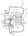
- a housing 10 which resembles the outer contour of a circuit breaker and is snapped onto a hat-profile mounting rail 11 shown in dashed lines two contact tracks 12, 14; 13, 15, which lie in pairs in one plane or with each other are aligned and spaced from each other.
- the one to be referenced Ends of the tracks 12, 14 and 13, 15 carry fixed contact pieces 16, 17; 18, 19, the on the ends attached in the usual way, preferably riveted.
- a first shaft journal 32 is provided, on which, as 3 to be explained, one in the axis of rotation and perpendicular to the plane of the drawing extending profiled pin 33 is provided.
- a Pinion section 34 attached to a gear section 35 of a second Shaft journal combs 36.
- first shaft journal 32 now rotates in the direction of the arrow U 1
- the second shaft journal 36 pivots in the direction of the arrow U 2 and the slide 20 is thereby displaced in the direction of the arrow P, so that the opened contact points are closed.
- the rotational movement of the first shaft journal 32 is converted via the second shaft journal 36 and the arm-like projection 37 into the rectilinear movement of the slide 20, which runs perpendicular to the fastening surface 23.
- FIG. 2 shows a further embodiment of the invention.
- the housing 10 is schematic and only partially drawn.
- a first pivots about an axis of rotation 40 Shaft journal 41, on which an arm 42 is formed.
- a second shaft journal 43 is rotatably mounted, on which a cam arm 44 is formed, which has a cam surface 45. Furthermore, the second one Shaft journal an arm-like projection 46, which with a ball head 47 in a recess 48 engages on the slider 49, which means in the same way as the slider 20 a spring 50 is pressed against the mounting surface 23.
- the slide 49 is penetrated by a contact bridge 51 at both ends
- Contact pieces 52, 53 are attached, each with corresponding fixed contact pieces form a contact point on a contact path 54 and 55.
- These contact pieces on the contact tracks 54 and 55 correspond, for example, to the contact tracks 13 and 15.
- the arm 42 has at its free end a slider 56 which against the Cam surface 45 abuts.
- the z. B. can be a residual current circuit breaker, an auxiliary switch 61 is attached, which is either the auxiliary switch according to FIG. 1 or 2 is the same.
- the installation switching device 60 has a switching shaft 62 which is on its end face 63 facing the auxiliary switch 61 has a profiled recess or recess 64 which flares outward; here is the cone shape clearly drawn.
- auxiliary switch 61 In the auxiliary switch 61 is the shaft journal 32, on which a profiled journal projection 65 is formed, which lies in the axis of rotation and which in the assembled state protrudes from the wall 66 of the auxiliary switch 61, the wall 67 of the installation switching device 60 reaches through and engages in the recess 64.
- the pin projection 65 has a profile shape corresponding to the recess 64, for example a square profile, and is tapered towards its free end.
- Means with which the first shaft journal 32 is guided and rotatably supported are in the Fig. 3 not shown. Of course, measures must be taken to ensure that the first shaft journal is rotatably but non-displaceably mounted in the housing 61.
Landscapes
- Driving Mechanisms And Operating Circuits Of Arc-Extinguishing High-Tension Switches (AREA)
- Breakers (AREA)
Abstract
Description
- Fig. 1
- eine erste Ausführungsform der Erfindung,
- Fig. 2
- eine zweite Ausführungsform der Erfindung, und
- Fig. 3
- eine Seitenansicht, teilweise geschnitten, zur Darstellung des ersten Wellenzapfens.
Claims (6)
- Hilfsschalter zum Anbau an ein elektrisches lnstallationsschaltgerät, beispielsweise an einem Fehlerstromschutzschalter oder Leitungsschutzschalter oder an einen FI/LS-Schalter zur Schallstellungsanzeige oder -meldung für das Installationsschaltgerät, mit wenigstens einer Kontaktbahn mit einer Kontaktstelle, die wenigstens ein feststehendes und wenigstens ein an einem beweglichen Hebel angebrachtes, bewegliches Kontaktstück aufweist, wobei die beweglichen Kontaktstücke mit einem Schieber gekoppelt sind, der wiederum mit einer Schaltwelle des lnstallationsschaltgerätes gekoppelt ist, dadurch gekennzeichnet, daß der Hilfsschalter einen ersten Wellenzapfen (32, 41) aufweist, der mit der Schaltwelle (62) des lnstallationsschaltgerätes (60) formschlüssig gekoppelt ist und der wenigstens einen Fortsatz (34, 42) aufweist, und einen zweiten Wellenzapfen (36, 43) enthält, der mit dem Fortsatz (34, 56) und dem Schieber (20) ebenfalls formschlüssig gekoppelt ist, dergestalt, daß die Drehung der Schaltwelle (62) den ersten Wellenzapfen (32, 41) und dessen Fortsatz (34, 42) in Drehung versetzt und der Fortsatz (34, 42) den zweiten Wellenzapfen (36, 43) und dieser den Schieber (20, 49) antreibt.
- Hilfsschalter nach Anspruch 1, dadurch gekennzeichnet, daß am ersten Wellenzapfen (32) mehrere Forsätze (34) angeformt sind, die miteinander einen Zahnritzelabschnitt bilden, und am zweiten Wellenzapfen (36) ein Zahnradabschnitt (35) angeformt sind, die beide miteinander kämmen, und daß am zweiten Wellenzapfen (36) ein Arm (37) angeformt ist, der in eine Ausnehmung (39) im Schieber greift.
- Hilfsschalter nach Anspruch 1, dadurch gekennzeichnet, daß der Fortsatz (42) ein Gleitarm ist, der mit einem Gleitstück (56) gegen eine Nockenfläche (45) am zweiten Wellenzapfen (43) zu dessen Verschwenkung anliegt und darauf gleitet.
- Hilfsschalter nach Anspruch 3, dadurch gekennzeichnet, daß an dem zweiten Wellenzapfen ein Nockenarm (44) mit der Nockenfläche (45) ein armartiger Vorsprung (46) angeformt ist, aufweist, der in eine Ausnehmung (48) im Schieber (49) eingreift.
- Hilfsschalter nach einem der vorherigen Ansprüche, dadurch gekennzeichnet, daß der erste Wellenzapfen (32, 41) einen in dessen Drehachse erstreckenden, profilierten, konisch sich verjüngenden Zapfenvorsprung (65) aufweist, der in eine passend profilierte Ausnehmung (64) in der Schaltwelle (62) des Installationsschaltgerätes (60) eingreift.
- Hilfsschalter nach Anspruch 5, dadurch gekennzeichnet, daß der Wellenzapfen (32, 41) mittels einer Feder (69) mit seinem Zapfenvorsprung (65) in die Ausnehmung oder Vertiefung (64) hineingedrückt ist.
Applications Claiming Priority (2)
| Application Number | Priority Date | Filing Date | Title |
|---|---|---|---|
| DE19910939 | 1999-03-12 | ||
| DE1999110939 DE19910939A1 (de) | 1999-03-12 | 1999-03-12 | Hilfsschalter zum Anbau an einen Fehlerstrom- oder Leitungsschutzschalter oder an einen Fl-/LS-Schalter |
Publications (2)
| Publication Number | Publication Date |
|---|---|
| EP1037243A2 true EP1037243A2 (de) | 2000-09-20 |
| EP1037243A3 EP1037243A3 (de) | 2002-01-02 |
Family
ID=7900654
Family Applications (1)
| Application Number | Title | Priority Date | Filing Date |
|---|---|---|---|
| EP00104137A Withdrawn EP1037243A3 (de) | 1999-03-12 | 2000-02-29 | Hilfsschalter zum Anbau an einen Fehlerstrom- oder Leitungsschutzschalter oder an einen FI-/LS-Schalter |
Country Status (3)
| Country | Link |
|---|---|
| EP (1) | EP1037243A3 (de) |
| DE (1) | DE19910939A1 (de) |
| PL (1) | PL338877A1 (de) |
Cited By (1)
| Publication number | Priority date | Publication date | Assignee | Title |
|---|---|---|---|---|
| CN122000250A (zh) * | 2026-04-09 | 2026-05-08 | 浙江索能电气集团有限公司 | 一种双连杆重合闸机构及断路器 |
Families Citing this family (1)
| Publication number | Priority date | Publication date | Assignee | Title |
|---|---|---|---|---|
| DE102023202388A1 (de) * | 2023-03-16 | 2024-09-19 | Siemens Aktiengesellschaft | Geräte-Modul, Reiheneinbaugerät und Kontaktfeder |
Family Cites Families (7)
| Publication number | Priority date | Publication date | Assignee | Title |
|---|---|---|---|---|
| DE7426189U (de) * | 1974-08-01 | 1974-11-07 | Bbc Ag | HilfGeschalter-Anbauteil für Leitungsschutzschalter |
| US4209761A (en) * | 1978-09-07 | 1980-06-24 | General Electric Company | Circuit breaker auxiliary switch apparatus |
| DE3603945A1 (de) * | 1986-02-07 | 1987-08-13 | Siemens Ag | Anbauschalter fuer schutzschalter |
| DE3712677A1 (de) * | 1986-12-12 | 1988-06-23 | Christian Geyer Gmbh & Co Elek | Antriebsmechanismen zum kuppeln elektrischer schaltgeraete |
| DE3920822C2 (de) * | 1989-06-24 | 1994-09-01 | Licentia Gmbh | Zusatzschalter zum Anbau an einen Leitungsschutzschalter |
| DE4013272A1 (de) * | 1990-04-26 | 1991-10-31 | Abb Patent Gmbh | Elektrisches schaltgeraet |
| IT1298784B1 (it) * | 1998-03-24 | 2000-02-02 | Abb Elettrocondutture Spa | Dispositivo di contatto ausiliario per interruttore magnetotermico |
-
1999
- 1999-03-12 DE DE1999110939 patent/DE19910939A1/de not_active Withdrawn
-
2000
- 2000-02-29 EP EP00104137A patent/EP1037243A3/de not_active Withdrawn
- 2000-03-08 PL PL33887700A patent/PL338877A1/xx not_active Application Discontinuation
Cited By (1)
| Publication number | Priority date | Publication date | Assignee | Title |
|---|---|---|---|---|
| CN122000250A (zh) * | 2026-04-09 | 2026-05-08 | 浙江索能电气集团有限公司 | 一种双连杆重合闸机构及断路器 |
Also Published As
| Publication number | Publication date |
|---|---|
| EP1037243A3 (de) | 2002-01-02 |
| DE19910939A1 (de) | 2000-09-14 |
| PL338877A1 (en) | 2000-09-25 |
Similar Documents
| Publication | Publication Date | Title |
|---|---|---|
| DE69825091T2 (de) | Trennschalter mit fünf Polen zur Phasenumkehr | |
| EP2446453B1 (de) | Sichtfenster und erdungskontaktanschluss für eine hochspannungsanordnung | |
| EP2174330B1 (de) | Mikroschalter | |
| DE69214707T2 (de) | Mechanische Verriegelung für ein Paar elektromagnetischer Schalter | |
| EP3671800B1 (de) | Trennklemme | |
| EP4006275A1 (de) | Bewegungsanordnung für eine türgriffanordnung | |
| EP0496213B1 (de) | Lastschalter, insbesondere Lastschalter mit Sicherung | |
| DE19501928C2 (de) | Einschubrahmen mit einer Trennkontaktanordnung | |
| DE2743042A1 (de) | Elektrischer steckverbinder | |
| EP2446454B1 (de) | Antrieb für einen elektrischen dreistellungsschalter | |
| DE69617074T2 (de) | Lasttrennschalter, auto-verriegelt in der geschlossenen Stellung der Lichtbogenkammern | |
| DE3147016C2 (de) | Hochspannungsschalter | |
| DE2923019C2 (de) | Hochspannungsschalter | |
| CH696476A5 (de) | Elektrische Schaltanordnung mit einem ersten Schaltkontakt und mit einem zweiten Schaltkontakt. | |
| DE102006041374B3 (de) | Antriebsverriegelung für zwei wechselseitig geöffnete und geschlossene Schalter eines Schaltfeldes | |
| DE19910939A1 (de) | Hilfsschalter zum Anbau an einen Fehlerstrom- oder Leitungsschutzschalter oder an einen Fl-/LS-Schalter | |
| EP0502394B1 (de) | Kontaktanordnung | |
| EP0454018A2 (de) | Elektrisches Schaltgerät | |
| EP0977222A2 (de) | Stromübertragungseinheit und Stromübertrager | |
| DE19850199C1 (de) | Trennschalter zur galvanischen Trennung von Stromschienen | |
| EP1197977A2 (de) | Lastumschalter für einen Stufenschalter | |
| DE202005015448U1 (de) | Elektromagnetisches Schaltgerät | |
| EP0938110A2 (de) | Vorrichtung für das ein- und ausschalten eines Elektromotors, insbesondere eines Elektrowerkzeugs | |
| DE69507231T2 (de) | Elektrisches Gerät, insbesondere Schalter für Säulen- oder Reihenmontage | |
| EP3815120B1 (de) | Antreiben eines elektrischen schaltkontaktes und eines meldeschalters |
Legal Events
| Date | Code | Title | Description |
|---|---|---|---|
| PUAI | Public reference made under article 153(3) epc to a published international application that has entered the european phase |
Free format text: ORIGINAL CODE: 0009012 |
|
| AK | Designated contracting states |
Kind code of ref document: A2 Designated state(s): AT BE CH CY DE DK ES FI FR GB GR IE IT LI LU MC NL PT SE |
|
| AX | Request for extension of the european patent |
Free format text: AL;LT;LV;MK;RO;SI PAYMENT 20000307 |
|
| RAP1 | Party data changed (applicant data changed or rights of an application transferred) |
Owner name: ABB PATENT GMBH |
|
| PUAL | Search report despatched |
Free format text: ORIGINAL CODE: 0009013 |
|
| AK | Designated contracting states |
Kind code of ref document: A3 Designated state(s): AT BE CH CY DE DK ES FI FR GB GR IE IT LI LU MC NL PT SE |
|
| AX | Request for extension of the european patent |
Free format text: AL;LT;LV;MK;RO;SI PAYMENT 20000307 |
|
| AKX | Designation fees paid |
Free format text: AT BE CH CY DE DK ES FI FR GB GR IE IT LI LU MC NL PT SE |
|
| AXX | Extension fees paid |
Free format text: SI PAYMENT 20000307 |
|
| STAA | Information on the status of an ep patent application or granted ep patent |
Free format text: STATUS: THE APPLICATION IS DEEMED TO BE WITHDRAWN |
|
| 18D | Application deemed to be withdrawn |
Effective date: 20020829 |