EP1036004B1 - Machine for attaching a tag to an infusion bag using an intermediate knotted thread - Google Patents
Machine for attaching a tag to an infusion bag using an intermediate knotted thread Download PDFInfo
- Publication number
- EP1036004B1 EP1036004B1 EP99941795A EP99941795A EP1036004B1 EP 1036004 B1 EP1036004 B1 EP 1036004B1 EP 99941795 A EP99941795 A EP 99941795A EP 99941795 A EP99941795 A EP 99941795A EP 1036004 B1 EP1036004 B1 EP 1036004B1
- Authority
- EP
- European Patent Office
- Prior art keywords
- thread
- machine according
- tag
- needles
- wheel
- Prior art date
- Legal status (The legal status is an assumption and is not a legal conclusion. Google has not performed a legal analysis and makes no representation as to the accuracy of the status listed.)
- Expired - Lifetime
Links
- 238000001802 infusion Methods 0.000 title claims abstract description 13
- 239000000047 product Substances 0.000 claims abstract description 16
- 238000000034 method Methods 0.000 claims abstract description 10
- 239000011265 semifinished product Substances 0.000 claims abstract description 9
- 230000001360 synchronised effect Effects 0.000 claims description 5
- 210000000887 face Anatomy 0.000 claims description 4
- 230000004913 activation Effects 0.000 claims 1
- 238000004804 winding Methods 0.000 claims 1
- 210000003128 head Anatomy 0.000 description 7
- 238000004806 packaging method and process Methods 0.000 description 4
- 238000005520 cutting process Methods 0.000 description 3
- 238000004519 manufacturing process Methods 0.000 description 3
- 238000013519 translation Methods 0.000 description 3
- 241001122767 Theaceae Species 0.000 description 1
- 241000826860 Trapezium Species 0.000 description 1
- 230000009471 action Effects 0.000 description 1
- 238000004026 adhesive bonding Methods 0.000 description 1
- 230000015572 biosynthetic process Effects 0.000 description 1
- 125000004122 cyclic group Chemical group 0.000 description 1
- 238000010586 diagram Methods 0.000 description 1
- 230000000694 effects Effects 0.000 description 1
- 230000005489 elastic deformation Effects 0.000 description 1
- 239000003292 glue Substances 0.000 description 1
- 230000036541 health Effects 0.000 description 1
- 239000012943 hotmelt Substances 0.000 description 1
- 230000003993 interaction Effects 0.000 description 1
- 230000007774 longterm Effects 0.000 description 1
- 239000000463 material Substances 0.000 description 1
- 239000002184 metal Substances 0.000 description 1
- 238000012986 modification Methods 0.000 description 1
- 230000004048 modification Effects 0.000 description 1
- 230000010355 oscillation Effects 0.000 description 1
- 230000000149 penetrating effect Effects 0.000 description 1
- 230000035515 penetration Effects 0.000 description 1
- 230000001681 protective effect Effects 0.000 description 1
- 238000012546 transfer Methods 0.000 description 1
- 238000011144 upstream manufacturing Methods 0.000 description 1
Images


Classifications
-
- B—PERFORMING OPERATIONS; TRANSPORTING
- B65—CONVEYING; PACKING; STORING; HANDLING THIN OR FILAMENTARY MATERIAL
- B65B—MACHINES, APPARATUS OR DEVICES FOR, OR METHODS OF, PACKAGING ARTICLES OR MATERIALS; UNPACKING
- B65B29/00—Packaging of materials presenting special problems
- B65B29/02—Packaging of substances, e.g. tea, which are intended to be infused in the package
- B65B29/04—Attaching, or forming and attaching, string handles or tags to tea bags
Definitions
- the present invention relates to machines for the automatic production of filter bags containing a product for infusion, such as tea, camomile or other similar products, the filter bags being made of filter paper, folded and closed with a knotted thread which connects them to the pick-up tag.
- a product for infusion such as tea, camomile or other similar products
- top-quality bags of product distinguished from similar bags by the fact that they prevent contact between the infusion and elements of the packaging which may, even to a limited degree, damage the health or (particularly important from a marketing viewpoint) modify the organoleptic characteristics of the infusion.
- Such effects are encountered, for example, in bags obtained by gluing sheets of filter paper with a hot-melt glue or even in bags in which the top is closed and the thread secured by metal staples.
- the present invention relates to an improved machine of the type comprising a wheel which rotates with a stepping motion about its own axis of rotation and is equipped with grippers which, as the wheel rotates, are brought into contact with a series of operating stations around the wheel, which comprise, in particular, a station for folding a tubular semi-finished product consisting of filter paper containing the dosed product, and at least one station for knotting the thread so as to close the top of the bag and attach the pick-up tag to it.
- a machine substantially corresponds with the preamble to claim 1 and is described in the application for an Italian patent BO95A000148 and an International patent application WO 96/31395.
- a machine of the above-mentioned type fulfils the aim of allowing high-quality bags to be obtained. However, it can be significantly improved in terms of increasing its productivity.
- the aim of the present invention is, therefore, to increase the production capacity of the machine through a corresponding increase in its operating speed.
- the machine in accordance with claim 1 comprises a knotting station equipped with a knotting device that has needles for knotting the thread to the tag and to the top of the filter bag, the needles being brought into contact with tag and bag-top stops and with respective mobile needle interceptor elements
- the same aim can also be achieved by creating, in the knotting stations, between the needle, thread and interceptor elements, reciprocal connection conditions predetermined by precise geometric constraints which allow the obtainment of conditions which can be repeated with great precision, even when the machine is operating at high speed.
- the above-mentioned aim is also achieved using a method for knotting the thread to the tag and to the top of the bag.
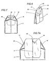
- the present invention relates to an improved machine 1 (see Figure 1) for packaging a product for infusion in filter bags 2, made of folded filter paper (see Figures 6, 7 and 7a), with a pick-up tag 3 tied to the filter bag 2 by a section 4 of thread 5 knotted at both ends, at one end to the filter bag 2 and at the other to the pick-up tag 3.
- the thread 5 not only connects the tag 3 and the filter bag 2, but also connects the tag 3 to the filter bag 2 in such a way that it can be removed, by a loop 62 made in the thread 5, engaged in the pick-up tag 3 and operating as described below.
- the machine 1 has a wheel 6 (see Figure 2) with a plurality of substantially radial grippers 7 at its edge.
- the wheel is surrounded by a series of operating stations respectively called the: semi-finished product reception station 8; semi-finished product folding station 9; first and second stations 10, 11 for forming the top 12 of a filter bag 2; thread 5 cutting station 13; tag 3 feed station 14; knotting station 15.
- the machine 1 receives in the direction of feed 18, substantially at a tangent to the wheel 6, the semi-finished products consisting of straight, extended tubular sections 20 of filter paper, said semi-finished products: obtained by folding the sheets of filter paper (fed from reels 20n) ; being open at both ends; and containing two doses 19 of a product for infusion, suitably spaced along the direction of feed 18.
- the manufacture of the classic two-lobed filter bag is made to the manufacture of the classic two-lobed filter bag.
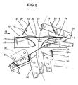
- the reception station 8 is equipped with a virtual reception table 21 for the sections 20, defined by three consecutive support surfaces 22, 23 and 24 (see Figures 8 and 9).
- Two support surfaces 22, 24 are fixed and positioned one after the other at a tangent to the direction of reception 18, so that they support the two ends of the section 20.
- the third support surface 23, located between the other two, is mobile across the direction of reception 18 of the section 20, synchronised with the section 20 feed, so that it is aligned with the fixed support surfaces 22, 24 immediately before the sections 20 arrive at the reception station 8.
- the machine 1 includes the semi-finished product 20 folding station 9.
- the latter has two continuous walls 25, 26, the ends of which incorporate the fixed support surfaces 22, 24 of the reception station 8 and which extend in such a way that they gradually converge towards a zone close to the edge of the wheel 6. It also has a gripper element 27, located opposite the mobile support surface 23 and, relative to the section 20, on the side opposite that which makes contact with the mobile support surface.
- the gripper element 27 and the mobile support surface 23 have matching operating ends, shaped in such a way that when they are clamped together in a zone located between the opposite ends of the section 20, they form a "W"-shaped fold 28 which separates two separate lobes in the filter bag 2.
- the gripper element 27 and the mobile support surface 23 can also move together between the walls 25, 26, both towards and away from the wheel 6.
- the folding station 9 also comprises two mobile pressure pads 29 with operating ends ( Figure 9a) shaped in such a way that they fit into a matching shape in the fixed walls 25, 26, defining a space 91 between them in which the open opposite ends of the tubular section 20 containing the product for infusion are clamped in such a way as to prevent the product 19 from escaping.
- Said pressure pads 29 are mobile, synchronised with the motion of the gripper element 27 and the mobile support surface 23 opposite it.
- each section 20 (see Figure 3A), after being received onto the support surfaces 22, 23, 24, is first clamped between the mobile central support surface 23 and the gripper element 27 to form the "W"-shaped fold 28, then transferred between the open teeth 30 of a gripper 7 which has moved to the folding station 9.
- the section 20, initially in a linear configuration is gradually positioned at an angle, with the lobes of the filter bag 2 folded against one another (see Figure 3B).
- the opposite ends of the tubular section 20 slide along the fixed walls 25, 26, clamped between the latter and the pressure pads 29 so that they remain closed, as already indicated, preventing the product in the filter bag 2 from escaping.
- the thread 5 for connecting the tag 3 to the filter bag 2 is fed continuously between the folding station 9 and the wheel 6.
- the thread is supported opposite the station by the teeth 30 of the various grippers 7, by support elements labelled 31 as a whole, which are attached to the wheel 6 on both sides of the grippers 7, are supported by the teeth 30 and comprise lateral projections 32 of the gripper 7 which project towards the thread 5.
- the thread 5 support elements 31 comprise friction surfaces set opposite one another and elastically separated by a spring element 32m which, in a preferred embodiment, consists of a leaf spring made of an elastic, flexible plate, attached to the projection 32 in such a way that it is subject to elastic deformation, when bent, and constantly presses against the projection 32.
- the thread 5 is held, by friction, between the opposite friction surfaces of the plate and the projection 32 and, although free to slide tangentially to the friction surfaces due to the drawing motion imparted to it by the rotation of the wheel 6 which unwinds it from a reel 37, it remains constantly taut between the consecutive support elements 31 of a gripper 7.
- the machine 1 has thread 5 feed means which comprise ( Figure 2a) a fork 33, with extended teeth 34, which are angled parallel with the axis of rotation 16 of the wheel 6 and supported, projecting horizontally, by an arm 35 which oscillates in the vertical plane between a home position, in which the teeth 34 are located outside the edge of the wheel 6, and an operating position, in which the teeth 34 are located within the edge of the wheel 6, between two consecutive grippers 7 on the wheel.
- the teeth 34 have flat lateral faces 36 which meet at vertices 67 respectively adjacent to two consecutive grippers 7 on the wheel 6.
- the teeth 34 intercept the thread 5 located between the support elements 31 of two consecutive grippers 7 and give it a segmented configuration, in which there are alternate sections of thread 5 in directions preferably corresponding to the radius and a chord of the wheel 6. This configuration allows considerable lengthening of the thread 5 subjected to the holding action implemented by the friction surfaces of the support elements 31, the faces 36 and vertices 67.
- FIGs 8 and 9 The interaction of the thread 5 with the folding station 9 is also illustrated in Figures 8 and 9.
- both indicate that, during folding of a tubular section 20, the thread 5 being unwound from the feed reel 37, remaining taut between the support elements 31 on the open teeth 30 of the gripper 7 (which has moved into position below the folding station 9) and also being held taut by the presence of the feed means 33, 34 which stop it from sliding backwards, is intercepted by the mobile support surface 23 (located between the tubular section 20 and the wheel 6) and is unwound from the reel 37 while being drawn through the teeth 30 of the gripper 7 and wound around the edge of the filter bag 2.
- the mobile support surface 23 Since the mobile support surface 23 consists of two elements with reciprocal penetration, parallel with the axis of rotation 16 of the wheel 6, and mobile relative to one another, controlling the disengagement of the two elements, the mobile support surface 23 is detached from the wheel 6 by the translation of at least one of the two elements, effected according to the axis of rotation 16. The support surface 23 then returns towards the reception station 8, whilst the wheel 6 is moved forward towards the first forming station 10 for the top 12 of the filter bag 2, with the filter bag 2 clamped between the closed teeth 30 of the gripper 7 ( Figure 3B).
- two side folds 38 of the top 12 are formed (see Figures 3B and 7), by interception, in the known manner, with fixed stop elements located on the outside of the wheel 6.
- the top 12 of the filter bag 2 forms an angle of around 90 ° to the rest of the filter bag 2 held in the gripper 7 and is angled forwards, according to the direction of rotation of the wheel 6.
- the thread 5 it should be noticed that, in the current situation, it is held taut by the support elements 31 on either side of the gripper 7 (projections 32 and springs 32m) and by the relative teeth 30.
- the cutting station 13 is activated before the gripper 7, standing by in the second forming station 11, is moved forward towards the tag 3 feed station 14.
- the filter bag 2 is surrounded by a section 4 of thread with lengths 40 held taut between the spring elements 32m and the teeth 30, which is separated from the uninterrupted thread 5 still attached to the grippers 7 which follow on the wheel 6.
- the gripper 7 is slightly opened and immediately closed again, so that its teeth 30 grip one end of the tag 3, which is held tightly against the filter bag 2 (see Figure 3D).
- the filter bag 2 is held between the closed teeth 30 of the gripper 7; the top 12 of the filter bag 2 is folded forward relative to the direction of rotation of the wheel 6; the tag 3 is folded back and the section 4 of thread 5, wrapped around the filter bag 2 and held by the gripper 7, has two lengths 40 which exit the gripper 7 and are held taut between the two teeth 30 of the gripper 7 and the adjacent spring elements 32m, on the lateral projections 32.
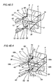
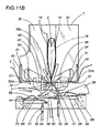
- the knotting station 15 comprises a knotting device 42 ( Figures 10, 11) with two operating heads 41 which are positioned on either side of the filter bag 2 when the wheel 6 stops and which, in particular, simultaneously connect the section 4 of thread 5 to the tag 3 on one side, and to the top 12 of the filter bag 2 on the other.
- each of the operating heads 41 of the knotting device 42 comprises a stop 43 for the tag 3 (or for the top 12 of the filter bag 2, depending which operating head 41 is considered), a presser body 50, a pressure pad 44, a needle 45, thread 5 positioning means, means 54 for threading the thread 5 and means for straightening the tag 3 and the top 12 of the filter bag 2, respectively labelled 58a and 58b.
- the stops 43 are preferably integral with one another, in a single block and, in particular, each one has a longitudinal cavity 46 passing through it, or an equivalent groove with an open side, which is straight and shaped in such a way that it matches the shape of the needles 45.
- These stops 43 are mobile, across the plane in which the wheel 6 lies, between a first, operating position, in which one of them is in contact with the tag 3 whilst the other is in contact with the top 12 of the filter bag 2, and a home position in which said stops 43 are moved parallel with the axis of rotation 16 of the wheel 6, in a position designed not to interfere with the rotation of the wheel 6.
- the presser body 50 (preferably a single body for the tag 3 and the top 12 of the filter bag 2) is positioned between the wheel 6 and the pressure pads 44 and is mobile, in a direction radial to the wheel 6, between a home position in which it is as far away as possible from the edge of the wheel 6, and an operating position in which it is as close as possible and is positioned next to the stop element 43.
- curved contact surfaces 48 which make contact with the tag 3 and the top 12 of the filter bag 2, said surfaces coming together at a point 49, substantially aligned with the axis of the gripper 7 standing by in the knotting station 15 and designed to insert itself between the tag 3 and the top 12 of the filter bag 2, holding them apart when it is in the position in which it is as close as possible to the wheel (see Figures 4E-4E-1 and Figures 10 and 11).
- the curved surfaces 48 are asymmetrical and at different distances from the axis of rotation 16 of the wheel 6.
- This feature allows the thread 5 to be knotted at points of the tag 3 and the top 12 of the filter bag which are at different distances from the ends of the gripper 7 teeth 30, allowing the top 12 of the filter bag 2 to be tied in such a way that a single knot ties off all three folds 38 and 39 on the top 12 (see Figure 7).
- Each pressure pad 44 comprises a support body 47, in which there are through-holes 72 for the needles 45, aligned with the longitudinal cavity 46 in the stop elements 43 above, and with the holes 78 in the presser body 50.
- Connected to the support body 47 there are two elastic plates 68, 69, with offset connection, which project end sections 70 and 71 towards the needles 45 at the relative free ends.
- the pressure pads 44 are mobile, suitably synchronised with the machine 1 operating cycle, between an operating position, in which the presser body 50 is in contact with the tag 3 and the top 12 of the filter bag 2, in contact with the stop elements 43, and a home position, in which they are positioned away from the wheel 6, so that they do not interfere with the rotation of the wheel 6.
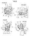
- Each needle 45 ( Figures 4, 10 and 11) has a first and a second eye 51, 52, located at different distances from the point.
- the eyes 51, 52 are positioned on the edge of the needles 45, have an open side and are angled in such a way that they cover two transversal planes of the needle 45, passing through the longitudinal axis of the needle 45 and set at right angles to one another.
- Each needle 45 is also mobile, being able to move in both directions along its longitudinal axis and to rotate about said axis (see Figures 4E, 1-4).
- the thread 5 positioning means comprise the gripper 7 teeth 30, the adjacent projections 32 and the leaf spring elements 32m.
- Figures 3 and 10 show how each length 40 of the thread (shown as a dashed line) which exits the closed teeth 30 of the gripper 7 is taut, in a well-defined position between the teeth 30 and the support elements 31, being positioned, as is explained below, on one side, in front of the longitudinal cavity 46 in the tag 3 stop element 43, and on the other side, in front of the corresponding cavity 46 in the stop element 43 for the top 12 of the filter bag 2.
- the threading means comprise two curved interceptor elements 54, in the shape of a circular arc (one for each of the operating heads 41), on a relative arm 55 which rotates about a centre of rotation 56 which substantially coincides with the centre of curvature of the respective interceptor element 54.
- Each interceptor element 54 is moved by relative drive means, not illustrated, in such a way that it is moved from a home position, at the side of the length 40 of thread 5, to an operating position in which the free end 57 intercepts the length 40 of thread 5 and is inserted into the eye 51 of the needle 45 closest to the point ( Figure 4E-4), passing through it.
- the tag 3 and filter bag 2 top 12 straightening means consist of pins 58a, 58b extending parallel with the axis of rotation 16 of the wheel 6 and moved by suitable drive means.
- One of the pins 58a has a pointed profile, forming an edge 66 designed to press the tag 3 against a first contact surface 48 on the presser body 50.
- the other pin 58b preferably has a cylindrical profile, is supported by a lever 59 and is designed to perform functions described below.
- Figures 10 and 11 show how the pin 58a for the tag 3 is moved, by the relative drive means, parallel with itself, along a curved trajectory 60, substantially monotonic and delimited by two end positions, in one of which the pin 58a clamps the tag 3 against the presser body 50, contributing to the curve in the tag along the contact surface 48; the pin 58a reaching the second end position when the tag 3 is in a flat configuration, favoured by the forward movement of the pin 58a towards the presser body 50 which, in the meantime, moves back towards its home position.
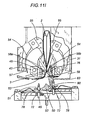
- the pin 58b for the top 12 of the filter bag 2 has a complex curved trajectory 61 (Figure 11M), having arcs with variable concavity, opposite one another along its length, for reasons which are explained in the description below.
- the lengths 40 of thread 5 (illustrated with a dashed line in Figure 10) are held taut between the ends of the teeth 30 and the relative lateral projections 32 located respectively on the same side as the tag 3 and on the same side as the top 12 of the filter bag 2 ( Figures 3D and 11A).
- the presser body 50 begins to move towards the position in which it is as close as possible to the wheel 6, positioning the tip 49 in the space between the tag 3 and the top 12 of the filter bag 2 ( Figures 4E and 11B). While the presser body 50 moves over a given length of its stroke towards the position in which it is closest to the wheel, both the pressure pads 44 below and the extended pins 58a, 58b move forward parallel with the axis 16 of rotation of the wheel 6, being inserted, on one side of the gripper 7, between a length 40 of thread and the tag 3, and on the other side of the gripper 7, between the other length 40 of thread and the top 12 of the filter bag 2.
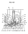
- the presser body 50 ( Figure 11C), the top 12 of the filter bag 2 and the tag 3 rest on the contact surfaces 48 of the presser body 50, assuming a corresponding curve.
- This curve is imposed on the tag 3, made of a material which is more rigid than the filter bag 2, partly thanks to the pin 58a which interacts with the opposite surface 48 of the presser body 50 and simultaneously moves towards the wheel 6 so that the tag 3 is curved by adapting it to the contact surface 48.
- the interceptor elements 54 are simultaneously moved towards the needles 45 ( Figures 11D and 11E). During the first part of their movement towards the needles 45, the two interceptor elements 54 intercept the respective lengths 40 of thread which, as a result, are arranged in a broken, mixed line, with a vertex 74 at the zone in which the end 57 of the interceptor elements 54 makes contact with the thread 5.
- the ends 57 of the interceptor elements 54 move, on both sides of the gripper 7, to the end sections 70 of the first elastic plates 68 relative respectively to the tag 3, and the top 12 of the filter bag 2.
- the thread 5 is clamped and held with its vertices 74 between the ends 57 of the interceptor elements 54 and the elastic plates 68, which are angled tangentially to the trajectory of the ends 57, and which make contact with the interceptor elements 54 as friction clamping means.
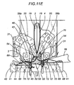
- the angle of the needles 45 about the axis is such that the segments of thread in the cavities 46 are caught in the eye 52 of the needles 45 furthest from the point.
- the translation of the needles 45 is inverted and the needles 45, moving in the opposite direction (see Figures 4E-2 and 11D), force the lengths 40 of thread 5 to pass through the tag 3 and the top 12 of the filter bag 2, forming corresponding loops 62 in which the thread 5 is doubled ( Figure 4E-2 and 11E).
- a subsequent rotation of the needles 45 about their longitudinal axes through an angle of at least 180o, or larger angles, for example, multiples of said angle allows the thread 5 to be wound around itself, tensioning and tightening the loop 62 which, when tightened, attaches the thread 5 close to the eye 51 closest to the point and, at the same time, allows the eye 51 to be angled relative to the trajectory of the interceptor elements 54.
- the interceptor elements 54 continue their forward movement (see Figures 4E-4 and 11F) towards the needles 45 and bring the section of thread 5 between the vertices 74 and the lateral projections 32 through the loops 62, interlacing the thread 5 (in such a way that, when tightened, it forms a knot 63) due to the thrust of the interceptor elements 54, which thread the thread 5 through the eyes 51 closest to the point of the needles 45.
- the interceptor elements 54 After passing through the loops 62, as the interceptor elements 54 move towards the end of their stoke, the thread 5, pushed by the ends 57, is forced between the end sections 71 of the second elastic plates 69 and the corresponding opposite contact surfaces 77 of the support body 47.
- the interceptor elements 54 After reaching the final position in which they are as close as possible to the needles 45, the interceptor elements 54 invert their direction of movement and, as the end 57 gradually disengages from the second elastic plate 69 ( Figure 11G), the thread 5 is released and remains held between the end 71 of the second elastic plate 69 and the surface 77 of the support body 47, which are in contact with one another.
- the extended pin 58b follows its trajectory 61, away from the axis of rotation 16 of the wheel 6 ( Figure 11L). During the final stage of said trajectory 61, the pin 58b performs a movement which causes the thread 5 to surround both the top 12 and the tag 3 of the filter bag 2 and, in particular, the small loop 64 formed by the excess thread 5 penetrates the notch 65 made in the tag 3 ( Figure 4E-6) in the previous feed station 14 ( Figure 11M).
- the loop 64 is then definitively released following the translation of the pin 58b parallel with the axis of rotation 16 of the wheel 6, proceeding towards its home position in which it allows the wheel 6 to rotate freely; the same movement occurring simultaneously for the pin 58a relative to the tag 3.
- the fully formed filter bag 2 is subjected to further operations, for example, packaging in a protective sachet 65b, operations which are not described, since they are not part of the subject matter of the present invention.
- interceptor elements 54 repeatedly interact firstly with the first elastic plate 68, then with the second elastic plate 69 and the relative opposite surface 77 of the support body 47, being subjected to complex cyclic stresses, of relatively high intensity considering the small dimensions of the interceptor elements 54. In the long-term, this may lead to some disadvantages in terms of their mechanical durability and reliability.
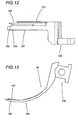
- an alternative embodiment illustrated in Figures 12 and 13 has interceptor elements 54 shaped like a curved fork, with two teeth 101 and 102, set side by side, which are of different sizes and shapes, and project from a single body 100.
- a first, larger tooth 101 has a free end 104 in the shape of an extended trapezium, slightly prominent relative to a much thinner free end 105 of the second tooth 102 which is tapered and finer than the first tooth 101 and has a projection 103, designed to intercept the thread 5.
- the projection 103 is located on the side of the second tooth 102 furthest from the first tooth 101 and is set back from the free end 105 of the second tooth 102.
- the teeth 101 and 102 and the projection 103 have separate functions, the second tooth 102 only drawing the thread 5 and the first tooth 101 moving the second plates 69 towards or away from the support body 47.
- the interceptor element 54 performs its characteristic alternating movements, the first tooth 101, having a free end 104 which projects further than the free end 105 of the second tooth 102, can insert itself between the second elastic plates 69 of the pressure pads 44 and the relative support body 47 before the free end 105 of the second tooth 102 reaches them.
Landscapes
- Engineering & Computer Science (AREA)
- Mechanical Engineering (AREA)
- Package Closures (AREA)
- Making Paper Articles (AREA)
- Labeling Devices (AREA)
- Medical Preparation Storing Or Oral Administration Devices (AREA)
- Packages (AREA)
Applications Claiming Priority (3)
| Application Number | Priority Date | Filing Date | Title |
|---|---|---|---|
| ITBO980536 | 1998-09-18 | ||
| IT1998BO000536A IT1305534B1 (it) | 1998-09-18 | 1998-09-18 | Macchina perfezionata per il confezionamento di sacchetti filtrocontenenti un prodotto da infusione provvisti di etichetta di presa |
| PCT/IB1999/001550 WO2000017055A2 (en) | 1998-09-18 | 1999-09-16 | Machine for attaching a tag to an infusion bag using an intermediate knotted thread |
Publications (2)
| Publication Number | Publication Date |
|---|---|
| EP1036004A1 EP1036004A1 (en) | 2000-09-20 |
| EP1036004B1 true EP1036004B1 (en) | 2005-05-25 |
Family
ID=11343408
Family Applications (1)
| Application Number | Title | Priority Date | Filing Date |
|---|---|---|---|
| EP99941795A Expired - Lifetime EP1036004B1 (en) | 1998-09-18 | 1999-09-16 | Machine for attaching a tag to an infusion bag using an intermediate knotted thread |
Country Status (8)
| Country | Link |
|---|---|
| US (1) | US6499273B1 (enExample) |
| EP (1) | EP1036004B1 (enExample) |
| JP (1) | JP4567197B2 (enExample) |
| AT (1) | ATE296228T1 (enExample) |
| DE (1) | DE69925455T2 (enExample) |
| ES (1) | ES2244207T3 (enExample) |
| IT (1) | IT1305534B1 (enExample) |
| WO (1) | WO2000017055A2 (enExample) |
Families Citing this family (28)
| Publication number | Priority date | Publication date | Assignee | Title |
|---|---|---|---|---|
| IT1313728B1 (it) * | 1999-09-15 | 2002-09-17 | Maisa Italia S R L | Apparecchiatura a mezzi rototraslatori e a pinze multiple perl'associazione di un'etichetta di presa e di un filo di manipolazione |
| US20050070945A1 (en) | 1999-11-02 | 2005-03-31 | Steven Schraga | Single use lancet assembly |
| US8814896B2 (en) | 1999-11-02 | 2014-08-26 | Stat Medical Devices, Inc. | Single use lancet assembly |
| IT1320887B1 (it) * | 2000-02-22 | 2003-12-10 | Ima Spa | Metodo per il confezionamento di sacchetti - filtro per prodotti dainfusione in relativi sovraincarti chiusi e relativa macchina attuante |
| DE50001378D1 (de) * | 2000-06-06 | 2003-04-10 | Teepack Spezialmaschinen | Teebeutel und Verfahren zum Verschliessen eines Teebeutels mittels eines Fadens |
| DE50003263D1 (de) * | 2000-06-06 | 2003-09-18 | Teepack Spezialmaschinen | Teebeutel mit einem an seinem Faden befestigten Etikett und Verfahren zum Befestigen eines Etiketts am Faden eines Teebeutels |
| US8715309B2 (en) | 2002-04-29 | 2014-05-06 | Steven Schraga | Lancet device |
| ITBO20020479A1 (it) * | 2002-07-23 | 2004-01-23 | Tecnomeccanica Srl | Apparato per formare automaticamente, con processo continuo, sovrabuste per contenimento di buste filtro contenenti a loro volta una sostanz |
| ITBO20020480A1 (it) * | 2002-07-23 | 2004-01-23 | Tecnomeccanica Srl | Macchina per formare una busta filtro per contenimento di una sostanza da infusione con accumulo di filo associato alla etichetta di presa |
| DE10317988A1 (de) * | 2003-04-19 | 2004-10-28 | Häussler & Sauter KG | Verfahren zur maschinellen Umschlingung eines Aufgussbeutels mit einem Zugfaden |
| EP1479612B1 (de) * | 2003-05-10 | 2005-12-14 | Teepack Spezialmaschinen Gmbh & Co. Kg | Verfahren und Vorrichtung zum Verknoten des Endes eines Fadens an einem flächigen Gegenstand |
| US7523595B2 (en) * | 2005-10-12 | 2009-04-28 | Haussier & Sauter Kg | Method for attaching a draw string to an infusion bag automatically |
| ITBO20070408A1 (it) * | 2007-06-11 | 2008-12-12 | I M A Ind Macchine Automatic H | Bustina monolobo per prodotti da infusione. |
| IT1401832B1 (it) * | 2010-09-30 | 2013-08-28 | Tecnomeccanica Srl | Metodo applicativo di un componente di una confezione di una sostanza da infusione. |
| ITBO20130478A1 (it) * | 2013-09-09 | 2015-03-10 | Roberto Conti | Macchina per formare sacchetti-filtro per prodotti da infusione con nodi. |
| EP3186154B1 (en) * | 2014-08-28 | 2017-12-13 | Azionaria Costruzioni Macchine Automatiche A.C.M.A. S.p.A. | Apparatus for producing packages of infusion products |
| EP3186152B1 (en) * | 2014-08-28 | 2018-11-21 | Azionaria Costruzioni Macchine Automatiche A.C.M.A. S.p.A. | Apparatus for producing packages of infusion products |
| EP3186153B1 (en) * | 2014-08-28 | 2017-11-29 | Azionaria Costruzioni Macchine Automatiche A.C.M.A. S.p.A. | Apparatus for producing packages of infusion products |
| ITUB20159642A1 (it) * | 2015-12-23 | 2017-06-23 | Ima Spa | Macchina per formare sacchetti-filtro per prodotti da infusione con stazione di piegatura. |
| ITUB20161017A1 (it) * | 2016-02-24 | 2017-08-24 | Ima Spa | Macchina per la formazione di sacchetti-filtro per prodotti da infusione. |
| IT201600076467A1 (it) * | 2016-07-21 | 2018-01-21 | Ima Spa | Macchina per formare sacchetti-filtro contenenti prodotti da infusione. |
| IT201600128479A1 (it) * | 2016-12-20 | 2018-06-20 | Ima Spa | Macchina per la formazione di sacchetti - filtro per prodotti da infusione. |
| IT201700074573A1 (it) * | 2017-07-04 | 2019-01-04 | Ima Spa | Macchina per la formazione di sacchetti - filtro per prodotti da infusione. |
| IT201700099539A1 (it) * | 2017-09-06 | 2019-03-06 | Ima Spa | Macchina per la formazione di sacchetti - filtro per prodotti da infusione. |
| DE102018101570A1 (de) * | 2018-01-24 | 2019-07-25 | Häussler & Sauter KG | Verfahren und Vorrichtung zur Herstellung von Aufgussbeuteln |
| EP3733383B1 (de) * | 2019-05-02 | 2022-12-21 | Teepack Spezialmaschinen Gmbh & Co. Kg | Vorrichtung und verfahren zum herstellen eines mit einer umhüllung versehenen, ein brühfähiges material enthaltenden beutels |
| IT201900017489A1 (it) * | 2019-09-30 | 2021-03-30 | Ima Spa | Macchina confezionatrice per la produzione di sacchetti-filtro con prodotti da infusione. |
| EP3960427B1 (de) | 2020-08-31 | 2025-01-01 | Teepack Spezialmaschinen GmbH & Co. KG | Vorrichtung zum herstellen eines in einer umhüllung aufgenommenen beutels |
Family Cites Families (9)
| Publication number | Priority date | Publication date | Assignee | Title |
|---|---|---|---|---|
| US3940169A (en) * | 1974-10-22 | 1976-02-24 | The Procter & Gamble Company | Loop knot tying method and apparatus |
| JPS5519246Y2 (enExample) | 1975-11-19 | 1980-05-07 | ||
| DE3642693C1 (de) | 1986-12-13 | 1988-07-07 | Groz & Soehne Theodor | Hakennadel(auch Hakenroehrnadel)fuer Naeh-,Stick-,Heftmaschinen und dergl. |
| DE3806386C1 (enExample) * | 1988-02-29 | 1989-03-09 | Teepack Spezialmaschinen Gmbh & Co Kg, 4005 Meerbusch, De | |
| GB9026123D0 (en) * | 1990-11-30 | 1991-01-16 | Unilever Plc | Tagged articles and method and apparatus for their production |
| GB9219657D0 (en) * | 1992-09-17 | 1992-10-28 | Unilever Plc | Tagged articles |
| WO1995032905A1 (en) * | 1994-05-27 | 1995-12-07 | I.M.A. Industria Macchine Automatiche S.P.A. | Method for closing a filter bag for infusible products and for connecting a tagged thread thereto |
| IT1274824B1 (it) * | 1994-07-08 | 1997-07-25 | Tecnomeccanica Srl | Metodo per l'associazione di una etichetta ad una busta-filtro per prodotti da infusione. |
| IT1282483B1 (it) * | 1995-04-04 | 1998-03-23 | Tecnomeccanica Srl | Macchina per il confezionamento di buste-filtro contenenti un prodotto da infusione provviste di etichetta di presa collegata alla busta |
-
1998
- 1998-09-18 IT IT1998BO000536A patent/IT1305534B1/it active
-
1999
- 1999-09-16 ES ES99941795T patent/ES2244207T3/es not_active Expired - Lifetime
- 1999-09-16 AT AT99941795T patent/ATE296228T1/de not_active IP Right Cessation
- 1999-09-16 DE DE69925455T patent/DE69925455T2/de not_active Expired - Lifetime
- 1999-09-16 EP EP99941795A patent/EP1036004B1/en not_active Expired - Lifetime
- 1999-09-16 WO PCT/IB1999/001550 patent/WO2000017055A2/en not_active Ceased
- 1999-09-16 JP JP2000573979A patent/JP4567197B2/ja not_active Expired - Lifetime
- 1999-09-16 US US09/530,806 patent/US6499273B1/en not_active Expired - Lifetime
Also Published As
| Publication number | Publication date |
|---|---|
| ES2244207T3 (es) | 2005-12-01 |
| US6499273B1 (en) | 2002-12-31 |
| ATE296228T1 (de) | 2005-06-15 |
| JP2002526337A (ja) | 2002-08-20 |
| WO2000017055A2 (en) | 2000-03-30 |
| IT1305534B1 (it) | 2001-05-09 |
| EP1036004A1 (en) | 2000-09-20 |
| DE69925455D1 (de) | 2005-06-30 |
| DE69925455T2 (de) | 2006-02-02 |
| ITBO980536A1 (it) | 2000-03-18 |
| WO2000017055A3 (en) | 2000-08-31 |
| JP4567197B2 (ja) | 2010-10-20 |
Similar Documents
| Publication | Publication Date | Title |
|---|---|---|
| EP1036004B1 (en) | Machine for attaching a tag to an infusion bag using an intermediate knotted thread | |
| EP0765274B1 (en) | Machine for infusion bags with a finger tab labels attached ther eto by interconnecting threads | |
| CA1046396A (en) | Automatic strapping machine | |
| EP0733548A1 (en) | Apparatus for packaging various products, particularly confectionery products having various shapes | |
| US4382355A (en) | Apparatus for the application of a thread having a label attached to it to a strip of filter paper in a machine for the automatic production of filter bags for the products to be infused | |
| US4856258A (en) | Wire tying device | |
| EP0879762B1 (en) | Method and apparatus for making infusion bags | |
| EP0912418B1 (en) | Infusion package and their manufacture | |
| US4625349A (en) | Bedding coil spring unit and assembly method | |
| CN107000862B (zh) | 用于生产沏泡产品包装的设备 | |
| CA1095554A (en) | Machine for automatically tying the ends of sausages and the like | |
| CA1151611A (en) | Method and apparatus for knotting automatically mouths of flexible packagings | |
| WO2000017054A1 (en) | Needle for attaching a tag to an infusion bag using an intermediate knotted thread | |
| US4262944A (en) | Broccoli bunching and tying machine | |
| US2556383A (en) | Tagging device | |
| US6711876B1 (en) | Apparatus for attaching a tag and a thread to a filter bag | |
| AU610107B2 (en) | Wire tying device | |
| US1499703A (en) | Machine for packaging articles | |
| EP0719707A1 (en) | Tying machine for closing a flexible container with a tying string | |
| SU1519955A1 (ru) | Устройство дл изготовлени и наложени зажима на жгут упаковочной сетки | |
| SU765122A1 (ru) | Устройство дл св зывани концов обв зочного материала | |
| IT8912618A1 (it) | Procedimento e macchina automatica per la produzione su scala industriale di fiocchi a due, a quattro o piu' anelli, utilizzabili ad esempio come ornamenti nell' abbigliamento e fiocchi cosi' ottenuti | |
| JPS6111351A (ja) | 提手製造取付装置 | |
| ITBO950581A1 (it) | Dispositivo per l'introduzione di oggetti piatti, in particolare cialde di prodotti per infusione,entro rispettivi involucri |
Legal Events
| Date | Code | Title | Description |
|---|---|---|---|
| PUAI | Public reference made under article 153(3) epc to a published international application that has entered the european phase |
Free format text: ORIGINAL CODE: 0009012 |
|
| AK | Designated contracting states |
Kind code of ref document: A1 Designated state(s): AT BE CH CY DE DK ES FI FR GB GR IE IT LI LU MC NL PT SE |
|
| D17D | Deferred search report published (deleted) | ||
| 17P | Request for examination filed |
Effective date: 20000613 |
|
| 17Q | First examination report despatched |
Effective date: 20031009 |
|
| GRAP | Despatch of communication of intention to grant a patent |
Free format text: ORIGINAL CODE: EPIDOSNIGR1 |
|
| GRAS | Grant fee paid |
Free format text: ORIGINAL CODE: EPIDOSNIGR3 |
|
| GRAA | (expected) grant |
Free format text: ORIGINAL CODE: 0009210 |
|
| AK | Designated contracting states |
Kind code of ref document: B1 Designated state(s): AT BE CH CY DE DK ES FI FR GB GR IE IT LI LU MC NL PT SE |
|
| PG25 | Lapsed in a contracting state [announced via postgrant information from national office to epo] |
Ref country code: NL Free format text: LAPSE BECAUSE OF FAILURE TO SUBMIT A TRANSLATION OF THE DESCRIPTION OR TO PAY THE FEE WITHIN THE PRESCRIBED TIME-LIMIT Effective date: 20050525 Ref country code: LI Free format text: LAPSE BECAUSE OF FAILURE TO SUBMIT A TRANSLATION OF THE DESCRIPTION OR TO PAY THE FEE WITHIN THE PRESCRIBED TIME-LIMIT Effective date: 20050525 Ref country code: FI Free format text: LAPSE BECAUSE OF FAILURE TO SUBMIT A TRANSLATION OF THE DESCRIPTION OR TO PAY THE FEE WITHIN THE PRESCRIBED TIME-LIMIT Effective date: 20050525 Ref country code: CH Free format text: LAPSE BECAUSE OF FAILURE TO SUBMIT A TRANSLATION OF THE DESCRIPTION OR TO PAY THE FEE WITHIN THE PRESCRIBED TIME-LIMIT Effective date: 20050525 Ref country code: BE Free format text: LAPSE BECAUSE OF FAILURE TO SUBMIT A TRANSLATION OF THE DESCRIPTION OR TO PAY THE FEE WITHIN THE PRESCRIBED TIME-LIMIT Effective date: 20050525 Ref country code: AT Free format text: LAPSE BECAUSE OF FAILURE TO SUBMIT A TRANSLATION OF THE DESCRIPTION OR TO PAY THE FEE WITHIN THE PRESCRIBED TIME-LIMIT Effective date: 20050525 |
|
| REG | Reference to a national code |
Ref country code: GB Ref legal event code: FG4D |
|
| REG | Reference to a national code |
Ref country code: CH Ref legal event code: EP |
|
| REG | Reference to a national code |
Ref country code: IE Ref legal event code: FG4D |
|
| REF | Corresponds to: |
Ref document number: 69925455 Country of ref document: DE Date of ref document: 20050630 Kind code of ref document: P |
|
| PG25 | Lapsed in a contracting state [announced via postgrant information from national office to epo] |
Ref country code: SE Free format text: LAPSE BECAUSE OF FAILURE TO SUBMIT A TRANSLATION OF THE DESCRIPTION OR TO PAY THE FEE WITHIN THE PRESCRIBED TIME-LIMIT Effective date: 20050825 Ref country code: GR Free format text: LAPSE BECAUSE OF FAILURE TO SUBMIT A TRANSLATION OF THE DESCRIPTION OR TO PAY THE FEE WITHIN THE PRESCRIBED TIME-LIMIT Effective date: 20050825 Ref country code: DK Free format text: LAPSE BECAUSE OF FAILURE TO SUBMIT A TRANSLATION OF THE DESCRIPTION OR TO PAY THE FEE WITHIN THE PRESCRIBED TIME-LIMIT Effective date: 20050825 |
|
| PG25 | Lapsed in a contracting state [announced via postgrant information from national office to epo] |
Ref country code: IE Free format text: LAPSE BECAUSE OF NON-PAYMENT OF DUE FEES Effective date: 20050916 Ref country code: CY Free format text: LAPSE BECAUSE OF FAILURE TO SUBMIT A TRANSLATION OF THE DESCRIPTION OR TO PAY THE FEE WITHIN THE PRESCRIBED TIME-LIMIT Effective date: 20050916 |
|
| PG25 | Lapsed in a contracting state [announced via postgrant information from national office to epo] |
Ref country code: MC Free format text: LAPSE BECAUSE OF NON-PAYMENT OF DUE FEES Effective date: 20050930 Ref country code: LU Free format text: LAPSE BECAUSE OF NON-PAYMENT OF DUE FEES Effective date: 20050930 |
|
| PG25 | Lapsed in a contracting state [announced via postgrant information from national office to epo] |
Ref country code: PT Free format text: LAPSE BECAUSE OF FAILURE TO SUBMIT A TRANSLATION OF THE DESCRIPTION OR TO PAY THE FEE WITHIN THE PRESCRIBED TIME-LIMIT Effective date: 20051027 |
|
| REG | Reference to a national code |
Ref country code: CH Ref legal event code: PL |
|
| NLV1 | Nl: lapsed or annulled due to failure to fulfill the requirements of art. 29p and 29m of the patents act | ||
| REG | Reference to a national code |
Ref country code: ES Ref legal event code: FG2A Ref document number: 2244207 Country of ref document: ES Kind code of ref document: T3 |
|
| PLBE | No opposition filed within time limit |
Free format text: ORIGINAL CODE: 0009261 |
|
| STAA | Information on the status of an ep patent application or granted ep patent |
Free format text: STATUS: NO OPPOSITION FILED WITHIN TIME LIMIT |
|
| ET | Fr: translation filed | ||
| 26N | No opposition filed |
Effective date: 20060228 |
|
| REG | Reference to a national code |
Ref country code: IE Ref legal event code: MM4A |
|
| REG | Reference to a national code |
Ref country code: GB Ref legal event code: 732E Free format text: REGISTERED BETWEEN 20091022 AND 20091028 |
|
| REG | Reference to a national code |
Ref country code: GB Ref legal event code: 732E Free format text: REGISTERED BETWEEN 20150226 AND 20150304 |
|
| REG | Reference to a national code |
Ref country code: FR Ref legal event code: PLFP Year of fee payment: 18 |
|
| REG | Reference to a national code |
Ref country code: FR Ref legal event code: PLFP Year of fee payment: 19 |
|
| REG | Reference to a national code |
Ref country code: FR Ref legal event code: PLFP Year of fee payment: 20 |
|
| PGFP | Annual fee paid to national office [announced via postgrant information from national office to epo] |
Ref country code: IT Payment date: 20180828 Year of fee payment: 20 Ref country code: FR Payment date: 20180822 Year of fee payment: 20 Ref country code: DE Payment date: 20180821 Year of fee payment: 20 |
|
| PGFP | Annual fee paid to national office [announced via postgrant information from national office to epo] |
Ref country code: GB Payment date: 20180823 Year of fee payment: 20 |
|
| PGFP | Annual fee paid to national office [announced via postgrant information from national office to epo] |
Ref country code: ES Payment date: 20181001 Year of fee payment: 20 |
|
| REG | Reference to a national code |
Ref country code: DE Ref legal event code: R071 Ref document number: 69925455 Country of ref document: DE |
|
| REG | Reference to a national code |
Ref country code: GB Ref legal event code: PE20 Expiry date: 20190915 |
|
| PG25 | Lapsed in a contracting state [announced via postgrant information from national office to epo] |
Ref country code: GB Free format text: LAPSE BECAUSE OF EXPIRATION OF PROTECTION Effective date: 20190915 |
|
| REG | Reference to a national code |
Ref country code: ES Ref legal event code: FD2A Effective date: 20201203 |
|
| PG25 | Lapsed in a contracting state [announced via postgrant information from national office to epo] |
Ref country code: ES Free format text: LAPSE BECAUSE OF EXPIRATION OF PROTECTION Effective date: 20190917 |