EP1035242B1 - Kurzketten-Schärmaschine - Google Patents
Kurzketten-Schärmaschine Download PDFInfo
- Publication number
- EP1035242B1 EP1035242B1 EP20000103680 EP00103680A EP1035242B1 EP 1035242 B1 EP1035242 B1 EP 1035242B1 EP 20000103680 EP20000103680 EP 20000103680 EP 00103680 A EP00103680 A EP 00103680A EP 1035242 B1 EP1035242 B1 EP 1035242B1
- Authority
- EP
- European Patent Office
- Prior art keywords
- selection lever
- warper according
- lever
- rod
- warper
- Prior art date
- Legal status (The legal status is an assumption and is not a legal conclusion. Google has not performed a legal analysis and makes no representation as to the accuracy of the status listed.)
- Expired - Lifetime
Links
Images
Classifications
-
- D—TEXTILES; PAPER
- D02—YARNS; MECHANICAL FINISHING OF YARNS OR ROPES; WARPING OR BEAMING
- D02H—WARPING, BEAMING OR LEASING
- D02H3/00—Warping machines
- D02H3/04—Sample warpers
Definitions
- the invention relates to a short chain warping machine with a lockable drum, on the at least one thread guide in one end face Feed plane revolves and on its circumference axially parallel Partial bars and conveyor belts that are placed on them Transport threads parallel to the axis, provided are, the partial rods on their of the said end face adjacent end have a selection element, that of an axial motor arranged inside the rod is adjustable in two positions to the threads to be placed either on or under the partial bar.
- the partial bars serve to form crosshairs or to separate threads can also be used for other purposes, e.g. For education a size division can be used.
- a hook is provided in one of the feed level penetrating axial slot back and forth can. It is driven by a pneumatic piston-cylinder unit, the inside of the hollow trained Partial bar is arranged and over one of the length of the partial rod corresponding air line from an outside of the rod arranged control valve actuated becomes.
- the hook is on one side of the Feed level, it pushes on the thread when actuated the sub-staff.
- the hook is on the other Side of the feed plane, he pushes the thread over that End of the partial rod, so that the thread over a The sloping part of the rod reaches under the partial rod.
- the invention has for its object a short chain warping machine of the type described in the introduction, in which the necessary for the assignment of the partial bars Thread selection even with shorter cycle times between two successive thread guide passes, works reliably.
- this object is achieved in that the selection element is formed by a selection lever which extends approximately radially to the drum and is pivotable about an axis at the end of the partial bar and its free end in the first position one side of the feed level and the second Position on the other side.
- the thread slides along one side of the separation lever, possibly over a known inclined surface, down to the sub-bar.
- the separation lever is located on the other hand, in the second position, slips the separated thread along the other side of the separation lever except for the partial bar.
- the separation element does not need to move threads and can therefore work faster under the same circumstances. Even a small swivel angle between the two Positions is sufficient to the free end of the selection lever to hike a relatively long way allow. Small swivel angles in turn allow high ones Working speeds. Still is a safe one Cutting the threads during the downtime of the selection lever guaranteed. One can therefore with higher machine speeds or simultaneously with one Variety of thread guides work.
- the pivot axis of the selection lever lies in the feed level.
- the two positions The selection lever can therefore be symmetrical to the feed level to be ordered. This gives the best results regarding the slipping of the selected threads on the selection lever and the most favorable ratio from a small swivel angle to a large path of free Ends of the selection lever between the two positions.
- the selection lever through an arm of a two-armed lever is formed, the second arm directed into the bar interior and over one Coupling element connected to the actuator of the axial motor is.
- the use of the two-armed lever and the Coupling link represents a particularly simple variant to the selection lever with the inside of the partial stack connected drive.
- pivot axis of the two-armed Lever opposite the axis of the actuator in Moved towards the free end of the selection lever is.
- the axis offset ensures that by lateral buckling of the coupling link and second arm the desired actuation of the selection lever takes place.
- the stop is a Damping pad carries. With very fast movement of the Selection lever, the damping pad lowers the noise level.
- the Axial motor is a pneumatic piston-cylinder unit which is supplied with compressed air via a control valve that is housed near the unit in the sub-staff is. Since the selection lever only selects the threads, but does not have to move on the partial rod and because relatively small swivel angles are sufficient for selection, can the pneumatic piston-cylinder unit run much smaller than before, such that the control valve is no longer outside the sub-rod, but can be accommodated in the sub-staff. As a result, A compressed air hose several meters long is not required between control valve and unit with the result that the piston is practically immediately after valve actuation responds and quickly adjusts the selection lever.
- a particularly recommendable solution is that there are several thread guides and the cycle time is less than 60 ms. Even with these short cycle times safe operation is still guaranteed.
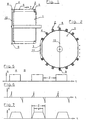
- Short chain warping machines of the type considered here those shown schematically in Figs. 1 and 2 Construction.
- An initially fixed drum 1 instructs their circumference conveyor belts 2 and - in secant sections - Partial bars 3.
- the conveyor belts are placed around pulleys 4 and 5. They are driven so that her outer run 6 is slowly heading towards arrow 7 moves.
- Two thread guides 8 and 9, attached to a common rotating support 10 put threads on the conveyor belts 2, so that over time the entire drum 1 with successively fed threads is wrapped.
- the partial rods 3 serve to form a crosshair, for separating or cutting the threads or for the department certain thread groups, as is known per se, for example from DE 197 17 443.
- Such a crosshair 11 is indicated in Fig. 2. It assumes that the threads normally deposited on the partial bars partially have to be placed under the partial rods 3. The present invention addresses this problem.
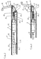
- the partial rod 3 is through a tube 12 is formed which has a slope at its end 13 has.
- a two-armed lever 14 has a selection lever 15 and a second arm 16 and is mounted rotatably about a pivot axis 17.
- the selection lever 15 can take two positions, namely the Position A shown in Fig. 3, in which the free End of the selection lever 15 on one side of the by the thread guides 8 and 9 determined feed plane 18th is located, and the position B shown in Fig. 4, in the the free end of the selection lever 15 on the other Side of the feed level 18 is located.
- the fed threads slide on the side surface 19 of the selection lever 15 down and get over the slope 13 under the sub-bar 3.
- the Threads either go directly to the Partial rod 3 or 20 through the other side surface of the selection lever 15 led there.
- An insert 21 carries a pneumatic piston-cylinder unit 22, the piston rod 23 with one in use 21 guided actuator 24 is connected, and the bearing for the pivot axis 17.
- the actuator 24 is a Joint 25 connected to a coupling element 26, the in turn via a joint 27 with the second arm 16 the double-armed lever 14 is connected.
- the piston rod 23 extends to the right the position A of FIG. 3, in which the second arm 16th is next to the slope 13.
- the piston rod is in moves in the opposite direction, the Position B of FIG. 4, in which the second lever arm 16 a stop provided with a damping buffer 28 29 is present.
- the location is such that the dead center position has not yet been reached, so because of the transfer the pivot axis 17 relative to the piston axis the next actuation of the piston-cylinder unit 22 the coupling member 26 pivots down again.
- Control valve 30 which via a line 31 with compressed air is supplied and this over two lines 32 optionally leads to one or the other side of the piston.
- the control valve 30 is operated by an electrical actuator 33 driven, the electrical Control lines 34 in turn in the cavity of the partial rod 3 run.
- the swivel angle was Selection lever 15 about 20 ° and the way to be covers the free end between positions A and B, was about 30 mm.
- the cylinder of the unit 22 had a diameter of 10 mm instead of 20 mm and the Stroke was only 10 mm instead of 25 mm previously.
- a control valve 30 in small format, whose dimensions allow it to be inside the Part 3 to be housed. As a result, no longer apply all delays so far due to long air supply hoses between the control valve and piston-cylinder unit were necessary.
- Fig. 5 shows over time the control commands S that the Actuating device 33 of the control valve 30 is supplied become.
- a full signal means that the position A ingested.
- missing signal means that position B should be taken.
- the control command is conveniently from a self-programmable Control (PLC) delivered and from the approaching Thread sensor 8 or 9 triggered.
- PLC self-programmable Control
- the duration of the individual commands therefore correspond to the cycle time z, that is, the time interval between successive ones Thread guide passages.
- Fig. 6 shows the speed v of the piston movement the piston-cylinder unit 22 over time. Since the Actuation of the piston practically without any delay starts with the actuation of the control valve 30 and the stroke to be traversed is relatively small reaches the desired position A or B very quickly.
Landscapes
- Engineering & Computer Science (AREA)
- Textile Engineering (AREA)
- Warping, Beaming, Or Leasing (AREA)
- Preliminary Treatment Of Fibers (AREA)
Description
- Fig. 1
- die Trommel einer Kurzketten-Schärmaschine in schematischer Darstellung,
- Fig. 2
- eine Stirnansicht der Maschine nach Fig. 1 in schematischer Darstellung,
- Fig. 3
- einen Schnitt durch das eine Ende des Teilstabes,
- Fig. 4
- einen Schnitt ähnlich Fig. 3 mit geänderten Stellung des Selektionshebels,
- Fig. 5
- die dem Steuerventil der Selektionsvorrichtung gegebenen Steuerbefehle über der Zeit,
- Fig. 6
- die Geschwindigkeit des Kolbens der pneumatischen Kolben-Zylinder-Einheit über der Zeit und
- Fig. 7
- den Weg der Selektionshebel über der Zeit.
Claims (11)
- Kurzketten-Schärmaschine mit einer feststellbaren Trommel, an deren einer Stirnseite mindestens ein Fadenführer in einer Zuführebene umläuft und an deren Umfang achsparallele Teilstäbe und Transportbänder, die die darauf gelegten Fäden achsparallel transportieren, vorgesehen sind, wobei die Teilstäbe an ihrem der genannten Stirnseite benachbarten Ende ein Selektionselement aufweisen, das von einem im Stabinnern angeordneten Axialmotor in zwei Stellungen verstellbar ist, um die Fäden wahlweise auf oder unter dem Teilstab zu plazieren, dadurch gekennzeichnet, daß das Selektionselement durch einen Selektionshebel (15) gebildet ist, der sich etwa radial zur Trommel (1) erstreckt und um eine Achse (17) am Ende des Teilstabes (3) schwenkbar ist und dessen freies Ende sich in der ersten Stellung (A) auf der einen Seite der Zuführebene (18) und in der zweiten Stellung (B) auf deren anderer Seite befindet.
- Schärmaschine nach Anspruch 1, dadurch gekennzeichnet, daß die Schwenkachse (17) des Selektionshebels (15) in der Zuführebene (18) liegt.
- Schärmaschine nach Anspruch 1 oder 2, dadurch gekennzeichnet, daß der Selektionshebel (15) durch einen Arm eines zweiarmigen Hebels (14) gebildet ist, dessen zweiter Arm (16) in das Stabinnere gerichtet und über ein Koppelglied (26) mit dem Stellglied (24) des Axialmotors verbunden ist.
- Schärmaschine nach Anspruch 3, dadurch gekennzeichnet, daß die Schwenkachse (17) des zweiarmigen Hebels (14) gegenüber der Achse des Stellgliedes (24) in Richtung auf das freie Ende des Selektionshebels (15) versetzt ist.
- Schärmaschine nach Anspruch 3 oder 4, dadurch gekennzeichnet, daß ein Anschlag (29) für den zweiten Arm (16) das Erreichen der Totpunktlage verhindert.
- Schärmaschine nach Anspruch 5, dadurch gekennzeichnet, daß der Anschlag (29) ein Dämpfungspolster (28) trägt.
- Schärmaschine nach Anspruch 5 oder 6, dadurch gekennzeichnet, daß der zweite Arm (16) zwischen dem Anschlag (29) und einer Schräge (13) auf der dem Selektionshebel (15) radial gegenüberliegenden Seite des Teilstabes (3) verschwenkbar ist.
- Schärmaschine nach einem der Ansprüche 1 bis 7, dadurch gekennzeichnet, daß der Axialmotor eine pneumatische Kolben-Zylinder-Einheit (22) ist, die über ein Steuerventil (30) mit Druckluft versorgt wird, das nahe der Einheit (22) im Teilstab (3) untergebracht ist.
- Schärmaschine nach Anspruch 8, dadurch gekennzeichnet, daß das Hubvolumen der pneumatischen Kolben-Zylinder-Einheit (22) kleiner als 10 cm2, vorzugsweise kleiner als 5 cm3 ist.
- Schärmaschine nach einem der Ansprüche 1 bis 3 gekennzeichnet durch eine solche Auslegung, daß die Stillstandszeiten (w) des Selektionshebels (15) mindestens 80% der Zykluszeit (z) zwischen zwei aufeinanderfolgenden Fadenführer-Durchgängen betragen.
- Schärmaschine nach Anspruch 10, dadurch gekennzeichnet, daß mehrere Fadenführer (8, 9) vorhanden sind und die Zykluszeit (z) kleiner als 60 ms ist.
Applications Claiming Priority (2)
| Application Number | Priority Date | Filing Date | Title |
|---|---|---|---|
| DE1999110833 DE19910833C1 (de) | 1999-03-11 | 1999-03-11 | Kurzketten-Schärmaschine |
| DE19910833 | 1999-03-11 |
Publications (2)
| Publication Number | Publication Date |
|---|---|
| EP1035242A1 EP1035242A1 (de) | 2000-09-13 |
| EP1035242B1 true EP1035242B1 (de) | 2004-01-07 |
Family
ID=7900592
Family Applications (1)
| Application Number | Title | Priority Date | Filing Date |
|---|---|---|---|
| EP20000103680 Expired - Lifetime EP1035242B1 (de) | 1999-03-11 | 2000-02-22 | Kurzketten-Schärmaschine |
Country Status (4)
| Country | Link |
|---|---|
| EP (1) | EP1035242B1 (de) |
| JP (1) | JP3418367B2 (de) |
| DE (2) | DE19910833C1 (de) |
| ES (1) | ES2208163T3 (de) |
Cited By (2)
| Publication number | Priority date | Publication date | Assignee | Title |
|---|---|---|---|---|
| TWI453732B (zh) * | 2008-07-11 | 2014-09-21 | Fraunhofer Ges Forschung | 時間扭曲輪廓計算器、音訊信號編碼器、編碼音訊信號表現型態、方法及電腦程式 |
| TWI463484B (zh) * | 2008-07-11 | 2014-12-01 | Fraunhofer Ges Forschung | 時間扭曲致動信號提供器、音訊信號編碼器、用以提供時間扭曲致動信號之方法、用以編碼音訊信號之方法及電腦程式 |
Families Citing this family (3)
| Publication number | Priority date | Publication date | Assignee | Title |
|---|---|---|---|---|
| DE10323352B4 (de) * | 2003-05-23 | 2006-09-14 | Karl Mayer Textilmaschinenfabrik Gmbh | Verfahren zum Erzeugen einer Musterkette und Musterkettenschärmaschine |
| DE502006001696D1 (de) * | 2006-07-26 | 2008-11-13 | Mayer Textilmaschf | Musterkettenschärmaschine und Verfahren zum Erzeugen eines Musterkettbaumes |
| CN109680382B (zh) * | 2019-01-22 | 2020-12-18 | 福建伟易泰智能科技有限公司 | 一种多纱检测的装置、绞纱头以及多纱检测的方法 |
Family Cites Families (6)
| Publication number | Priority date | Publication date | Assignee | Title |
|---|---|---|---|---|
| DE1245875B (de) * | 1965-04-03 | 1967-07-27 | Hergeth K G Maschinenfabrik Un | Verfahren und Vorrichtung zur Herstellung von Kurzketten, insbesondere fuer Gewebemuster in der Buntweberei |
| JPH02169737A (ja) * | 1988-12-22 | 1990-06-29 | Suzuki Waapaa:Kk | 複本数同時整経可能な電子制御サンプル整経機 |
| JP2854789B2 (ja) * | 1993-11-09 | 1999-02-03 | 有限会社スズキワーパー | 整列巻き可能な電子制御サンプル整経機 |
| DE19717443C1 (de) * | 1997-04-25 | 1999-01-14 | Mayer Textilmaschf | Verfahren zur Herstellung einer Kurzkette und Einzelfaden-Kurzketten-Schärmaschine zur Durchführung des Verfahrens |
| JP3416463B2 (ja) * | 1997-06-03 | 2003-06-16 | 有限会社スズキワーパー | 糸交換機構付電子制御サンプル整経機 |
| DE19845244C1 (de) * | 1998-10-01 | 1999-09-23 | Mayer Textilmaschf | Musterketten-Schärmaschine |
-
1999
- 1999-03-11 DE DE1999110833 patent/DE19910833C1/de not_active Expired - Fee Related
-
2000
- 2000-02-22 EP EP20000103680 patent/EP1035242B1/de not_active Expired - Lifetime
- 2000-02-22 ES ES00103680T patent/ES2208163T3/es not_active Expired - Lifetime
- 2000-02-22 DE DE50004957T patent/DE50004957D1/de not_active Expired - Fee Related
- 2000-03-06 JP JP2000060177A patent/JP3418367B2/ja not_active Expired - Fee Related
Cited By (2)
| Publication number | Priority date | Publication date | Assignee | Title |
|---|---|---|---|---|
| TWI453732B (zh) * | 2008-07-11 | 2014-09-21 | Fraunhofer Ges Forschung | 時間扭曲輪廓計算器、音訊信號編碼器、編碼音訊信號表現型態、方法及電腦程式 |
| TWI463484B (zh) * | 2008-07-11 | 2014-12-01 | Fraunhofer Ges Forschung | 時間扭曲致動信號提供器、音訊信號編碼器、用以提供時間扭曲致動信號之方法、用以編碼音訊信號之方法及電腦程式 |
Also Published As
| Publication number | Publication date |
|---|---|
| DE19910833C1 (de) | 2000-05-31 |
| ES2208163T3 (es) | 2004-06-16 |
| JP3418367B2 (ja) | 2003-06-23 |
| DE50004957D1 (de) | 2004-02-12 |
| JP2000256931A (ja) | 2000-09-19 |
| EP1035242A1 (de) | 2000-09-13 |
Similar Documents
| Publication | Publication Date | Title |
|---|---|---|
| DE3832124A1 (de) | Elektronische vorrichtung fuer die automatische einstellung von industrie-naehmaschinen | |
| DE3307301C2 (de) | ||
| DE3422661A1 (de) | Vorrichtung zum zufuehren von abgelaengten laengsdraehten zu einer gitterschweissmaschine | |
| DE2129973B2 (de) | Vorrichtung zur Bildung von Fadenreserven bei OHen-End-Splnnmaechinen | |
| DE69227926T2 (de) | Antriebsvorrichtung zur Übertragung von horizontalen hin- und hergehenden Bewegungen zu Hülsentragbarren an Strickmaschinen | |
| DE3733692C2 (de) | ||
| EP1035242B1 (de) | Kurzketten-Schärmaschine | |
| DE3016849C2 (de) | ||
| DE2349018B2 (de) | Vorrichtung zum Ausgleichen der sich ändernden Entfernung zwischen dem hin- und herbewegten Changierfadenführer und einem feststehenden Fadenführer für die Zuführung des Fasergutes bei Spulmaschinen | |
| EP0051223A1 (de) | Verfahren und Vorrichtung zum Einführen von Fäden und dergleichen in eine Spulvorrichtung | |
| DE10323382B4 (de) | Verfahren zum Erzeugen einer Musterkette und Musterkettenschärmaschine | |
| DE717801C (de) | Spulmaschine | |
| DE10302254B4 (de) | Verfahren zum Erzeugen einer Musterkette und Musterkettenschärmaschine | |
| DE10057356B4 (de) | Verfahren zum Erzeugen einer Musterkette und Musterketten-Schärmaschine | |
| DE10057354B4 (de) | Verfahren zum Erzeugen einer Musterkette und Musterketten-Schärmaschine | |
| DE1535035A1 (de) | Vorrichtung zum Steuern des Spulenaufbaues an Vorspinnmaschinen | |
| DE761309C (de) | Maschine zum Bewickeln der genuteten Staender von elektrischen Maschinen | |
| CH221905A (de) | Verfahren zum Vorspinnen von Fasern und Maschine zur Ausführung des Verfahrens. | |
| DE3915608A1 (de) | Aufspulmaschine | |
| DE1627233A1 (de) | Fliegende Schere | |
| DE503970C (de) | Fadenknuepfvorrichtung | |
| DE2155125C3 (de) | Hubvorrichtung einer Greiferbank einer selbsttätigen Hülsenwechseleinrichtung | |
| DE870662C (de) | Koetzerspulmaschine od. dgl. | |
| DE308904C (de) | ||
| DE174091C (de) |
Legal Events
| Date | Code | Title | Description |
|---|---|---|---|
| PUAI | Public reference made under article 153(3) epc to a published international application that has entered the european phase |
Free format text: ORIGINAL CODE: 0009012 |
|
| AK | Designated contracting states |
Kind code of ref document: A1 Designated state(s): CH DE ES IT LI |
|
| AX | Request for extension of the european patent |
Free format text: AL;LT;LV;MK;RO;SI |
|
| 17P | Request for examination filed |
Effective date: 20000803 |
|
| AKX | Designation fees paid |
Free format text: CH DE ES IT LI |
|
| GRAP | Despatch of communication of intention to grant a patent |
Free format text: ORIGINAL CODE: EPIDOSNIGR1 |
|
| GRAS | Grant fee paid |
Free format text: ORIGINAL CODE: EPIDOSNIGR3 |
|
| GRAA | (expected) grant |
Free format text: ORIGINAL CODE: 0009210 |
|
| AK | Designated contracting states |
Kind code of ref document: B1 Designated state(s): CH DE ES IT LI |
|
| REG | Reference to a national code |
Ref country code: CH Ref legal event code: EP |
|
| REG | Reference to a national code |
Ref country code: CH Ref legal event code: NV Representative=s name: BOVARD AG PATENTANWAELTE |
|
| REF | Corresponds to: |
Ref document number: 50004957 Country of ref document: DE Date of ref document: 20040212 Kind code of ref document: P |
|
| REG | Reference to a national code |
Ref country code: ES Ref legal event code: FG2A Ref document number: 2208163 Country of ref document: ES Kind code of ref document: T3 |
|
| PLBE | No opposition filed within time limit |
Free format text: ORIGINAL CODE: 0009261 |
|
| STAA | Information on the status of an ep patent application or granted ep patent |
Free format text: STATUS: NO OPPOSITION FILED WITHIN TIME LIMIT |
|
| 26N | No opposition filed |
Effective date: 20041008 |
|
| PGFP | Annual fee paid to national office [announced via postgrant information from national office to epo] |
Ref country code: CH Payment date: 20080225 Year of fee payment: 9 Ref country code: ES Payment date: 20080221 Year of fee payment: 9 |
|
| PGFP | Annual fee paid to national office [announced via postgrant information from national office to epo] |
Ref country code: DE Payment date: 20080220 Year of fee payment: 9 |
|
| REG | Reference to a national code |
Ref country code: CH Ref legal event code: PL |
|
| PG25 | Lapsed in a contracting state [announced via postgrant information from national office to epo] |
Ref country code: LI Free format text: LAPSE BECAUSE OF NON-PAYMENT OF DUE FEES Effective date: 20090228 Ref country code: CH Free format text: LAPSE BECAUSE OF NON-PAYMENT OF DUE FEES Effective date: 20090228 |
|
| PG25 | Lapsed in a contracting state [announced via postgrant information from national office to epo] |
Ref country code: DE Free format text: LAPSE BECAUSE OF NON-PAYMENT OF DUE FEES Effective date: 20090901 |
|
| REG | Reference to a national code |
Ref country code: ES Ref legal event code: FD2A Effective date: 20090223 |
|
| PG25 | Lapsed in a contracting state [announced via postgrant information from national office to epo] |
Ref country code: ES Free format text: LAPSE BECAUSE OF NON-PAYMENT OF DUE FEES Effective date: 20090223 |
|
| PGFP | Annual fee paid to national office [announced via postgrant information from national office to epo] |
Ref country code: IT Payment date: 20190222 Year of fee payment: 20 |