EP1034979B1 - Plage arrière pour vehicules avec capote pliante - Google Patents
Plage arrière pour vehicules avec capote pliante Download PDFInfo
- Publication number
- EP1034979B1 EP1034979B1 EP00104877A EP00104877A EP1034979B1 EP 1034979 B1 EP1034979 B1 EP 1034979B1 EP 00104877 A EP00104877 A EP 00104877A EP 00104877 A EP00104877 A EP 00104877A EP 1034979 B1 EP1034979 B1 EP 1034979B1
- Authority
- EP
- European Patent Office
- Prior art keywords
- guide
- rear window
- window shelf
- pivot
- lever
- Prior art date
- Legal status (The legal status is an assumption and is not a legal conclusion. Google has not performed a legal analysis and makes no representation as to the accuracy of the status listed.)
- Expired - Lifetime
Links
Images


Classifications
-
- B—PERFORMING OPERATIONS; TRANSPORTING
- B60—VEHICLES IN GENERAL
- B60J—WINDOWS, WINDSCREENS, NON-FIXED ROOFS, DOORS, OR SIMILAR DEVICES FOR VEHICLES; REMOVABLE EXTERNAL PROTECTIVE COVERINGS SPECIALLY ADAPTED FOR VEHICLES
- B60J7/00—Non-fixed roofs; Roofs with movable panels, e.g. rotary sunroofs
- B60J7/08—Non-fixed roofs; Roofs with movable panels, e.g. rotary sunroofs of non-sliding type, i.e. movable or removable roofs or panels, e.g. let-down tops or roofs capable of being easily detached or of assuming a collapsed or inoperative position
- B60J7/12—Non-fixed roofs; Roofs with movable panels, e.g. rotary sunroofs of non-sliding type, i.e. movable or removable roofs or panels, e.g. let-down tops or roofs capable of being easily detached or of assuming a collapsed or inoperative position foldable; Tensioning mechanisms therefor, e.g. struts
- B60J7/14—Non-fixed roofs; Roofs with movable panels, e.g. rotary sunroofs of non-sliding type, i.e. movable or removable roofs or panels, e.g. let-down tops or roofs capable of being easily detached or of assuming a collapsed or inoperative position foldable; Tensioning mechanisms therefor, e.g. struts with a plurality of rigid plate-like elements or rigid non plate-like elements, e.g. with non-slidable, but pivotable or foldable movement
- B60J7/143—Non-fixed roofs; Roofs with movable panels, e.g. rotary sunroofs of non-sliding type, i.e. movable or removable roofs or panels, e.g. let-down tops or roofs capable of being easily detached or of assuming a collapsed or inoperative position foldable; Tensioning mechanisms therefor, e.g. struts with a plurality of rigid plate-like elements or rigid non plate-like elements, e.g. with non-slidable, but pivotable or foldable movement for covering the passenger compartment
- B60J7/145—Non-fixed roofs; Roofs with movable panels, e.g. rotary sunroofs of non-sliding type, i.e. movable or removable roofs or panels, e.g. let-down tops or roofs capable of being easily detached or of assuming a collapsed or inoperative position foldable; Tensioning mechanisms therefor, e.g. struts with a plurality of rigid plate-like elements or rigid non plate-like elements, e.g. with non-slidable, but pivotable or foldable movement for covering the passenger compartment at least two elements being folded in clamp-shell fashion
-
- B—PERFORMING OPERATIONS; TRANSPORTING
- B60—VEHICLES IN GENERAL
- B60J—WINDOWS, WINDSCREENS, NON-FIXED ROOFS, DOORS, OR SIMILAR DEVICES FOR VEHICLES; REMOVABLE EXTERNAL PROTECTIVE COVERINGS SPECIALLY ADAPTED FOR VEHICLES
- B60J7/00—Non-fixed roofs; Roofs with movable panels, e.g. rotary sunroofs
- B60J7/20—Vehicle storage compartments for roof parts or for collapsible flexible tops
- B60J7/202—Vehicle storage compartments for roof parts or for collapsible flexible tops being characterised by moveable cover parts for closing the gap between boot lid and rearmost seats
-
- B—PERFORMING OPERATIONS; TRANSPORTING
- B60—VEHICLES IN GENERAL
- B60R—VEHICLES, VEHICLE FITTINGS, OR VEHICLE PARTS, NOT OTHERWISE PROVIDED FOR
- B60R5/00—Compartments within vehicle body primarily intended or sufficiently spacious for trunks, suit-cases, or the like
- B60R5/04—Compartments within vehicle body primarily intended or sufficiently spacious for trunks, suit-cases, or the like arranged at rear of vehicle
- B60R5/044—Compartments within vehicle body primarily intended or sufficiently spacious for trunks, suit-cases, or the like arranged at rear of vehicle luggage covering means, e.g. parcel shelves
- B60R5/045—Compartments within vehicle body primarily intended or sufficiently spacious for trunks, suit-cases, or the like arranged at rear of vehicle luggage covering means, e.g. parcel shelves collapsible or transformable
Definitions
- the invention relates to a parcel shelf for vehicles with Hinged top according to the preamble of claim 1.
- Such parcel shelves are generally known.
- Vehicles with a folding top are available as convertibles or Roadster known, the top as a folding top or as Hard top can be formed.
- the top In the open state it is recorded in a so-called convertible top compartment, some of which lies between the interior of the vehicle and the trunk, partly, especially with hardtops, also parts of the trunk claimed.
- the convertible top is not closed on one Convertible top compartment lid attached, so it forms, for example following the trunk lid in the closed state part of the cover of the convertible top compartment, which against the Vehicle interior is covered by a parcel shelf that is opened to open and close the convertible top and the one opened when lowered into the convertible top compartment Convertible top, then, for example, to the trunk lid covers the remaining opening of the convertible top compartment. Solutions of this kind are known from practice.
- Foldable tops are automated and inclusive the associated convertible top compartment covers, such as also hat racks are controlled in their sequence so that none further intervention by an operator is required, so there are complicated mechanics and a high one Control effort.
- the invention has for its object for vehicles with Folding top according to the preamble of claim 1 to create a control for a parcel shelf that stands out is characterized by a simple working principle and the result in Integrate convertible top controls as part of overall kinematics is.
- the guide points assigned to the parcel shelf and Rotary axes enable control with motion sequences, which is not prone to dead spots and where one of the Drive for the convertible top independent, independent actuator may be dispensed with for the parcel shelf can.
- the solution according to the invention of the management of the parcel shelf over two, based on a lying hat cover in Height-spaced guide points that alternate serve as axes of rotation, makes opening and closing the Parcel shelf with simultaneous shift in the longitudinal direction with simple means possible, the drive for the Rotational movements and the longitudinal offset preferred in simpler Way can be done via the drive for the roof guide.
- the control and management of the parcel shelf is according to the invention constructively easy to control when the Guide points in their function as axes of rotation Form guide points, the required ones This has a positive effect on the turning and offset paths let the guide points within the scope of the invention in Longitudinal direction of the vehicle offset from each other become.
- the guide points preferably form based on the first, with the roof closed given closed position of the parcel shelf, the upper guide point a first guide point in this first closed position the parcel shelf in the direction of the longitudinal offset of the parcel shelf between the first and second closed position compared to the second, lower guide point is offset.
- This basic arrangement makes it possible to start from the the first closed position of the parcel shelf the first guide point first use as a fixed axis of rotation around which the second The guide point is pivoted while opening the cover, being the pivot for the second guide point at the same time an offset in the direction of the longitudinal offset the parcel shelf towards the second closed position. Becomes now the second guide point offset in the longitudinal direction used as a fixed axis of rotation, so with the closing movement a longitudinal offset for the parcel shelf the same connected.
- the movement of the convertible top or of it Guide links used with simple mechanical means be coordinated to the guide points of the parcel shelf relocate and initiate appropriate rotary movements.
- control of the invention Hat rack in connection with convertible top structures advantageous insert that have a four-jointed roof guide, in the two body-fixed, in the longitudinal direction of the Vehicle spaced axes of rotation for two pivotable and linked guide links are provided, if each of the guide points of the parcel shelf is one over one of the guide links controlled guide linkage is assigned.
- This release can depend on the position of the first control arm can be reached automatically if this according to the invention with the first guide point associated guide linkage cooperates such that this - based on a given position of the first Leadership - from his fixation on the first Control arm is released. If the fixation is released, it can
- the support of the convertible top control assigned actuator for example a working cylinder against this guide linkage can be used to the parcel shelf around its second guide point as a pivot axis to pivot, with the actuator under the Construction according to the invention for this adjustment of the Parcel shelf can maintain the same positioning direction that for the convertible top from its closed position in its open position, stored in the convertible top compartment, is necessary was.
- a control of the parcel shelf in a convertible top control integrate in a simple way, becoming too Let dead positions tend to avoid leading positions and with a common drive for controlling the convertible top and the parcel shelf can be worked.
- the hat rack control according to the invention also with the Convertible top control on both sides of the vehicle in the same Realize training easily because the solution according to the invention only a few additional articulation points compared to the body requires and is insensitive to tolerance.
- FIG. 1 shows a schematic representation of the rear Part of a vehicle 1 which has a convertible top 2 that is to be opened has, which is between the indicated here Windshield frame 3 and the rear provided Trunk cover 4 extends, the top 2 through a so-called hardtop is formed, which one to the Windshield frame 3 adjoining roof section 5 as well comprises a rear window part 6. Roof part 5 and rear window part 6 of the convertible top 2 are for opening the convertible top 2 in a convertible top compartment 7, which is essentially above the wheel section 8 between the vehicle interior and Trunk 9 extends, part of the trunk 9 is used by the top compartment 7.
- roof part 5 and rear window part 6 are as Forced guidance formed and by a four-bar transmission 10 formed, which is shown essentially only schematically is and a front guide link 11, one rear guide link 12 and a coupling 13 includes the guide link 11, 12, of which the guide link 11 is designed here as a two-armed handlebar body-fixed pivot axes are pivotable.
- Guide devices are, via roof part 5 and rear window part 6 connected, in a symmetrical arrangement on both Provided sides of the vehicle 1 and each include an actuator 14 by an actuating cylinder is illustrated.
- this longitudinal displacement takes place in connection with the opening and closing of the parcel shelf 19, as is the case with Sinking the top 2 in the top compartment 7 and at Extend the convertible top 2 from the convertible top compartment 7 is required. Further details and characteristics of the Known top construction according to Figure 1 result from DE 44 45 580 C1.
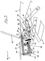
- a control of a rear shelf 19 in the manner according to the invention serve, based on a first embodiment, the figures 2 to 9, the rear shelf 19 being forcibly coupled to the convertible top 2 is arranged and accordingly when pivoting the top 2 is carried along.
- a common drive for convertible top 2 and parcel shelf 19 is provided, while maintaining its respective Direction of advance, which for the opening and the Closing process is opposite, the opening or closing process continuously.
- FIG 2 are of the four-link transmission assigned to the roof 10 only the front guide link 11 and the rear guide link 12 illustrated. From further Convertible top only the rear window part 6 is indicated schematically.
- the pivot axis for the front guide link 11 is with 15 and the pivot axis for the rear guide link 12 designated 16.
- Figure 3 additionally illustrates how the individual lever and handlebars of the guide rods 17 and 18 and of the four-bar linkage 10 in association with the rear shelf 19 whose drive and leadership work together.
- the parcel shelf 19 upstream - in the transition to the vehicle interior - is one Panel 43 by the parcel shelf 19 in its first The closed position is partially undershot.
- the rear shelf 19 is on its underside, i.e. their in the Closed positions of the top compartment 7 facing side 20, the Guide rods 17 and 18 associated with a console 21 provided which, spaced in the vertical direction, i.e. in different distance from the underside 20 of the rear shelf 19, a first guide point 22 and a second guide point 23, wherein in the first guide point 22 the front Guide linkage 17 and 23 in the second guide point rear guide linkage 18 connected to the console 21 is.
- the guide rods 17 and 18 are each by a Pair of levers formed, the levers of the guide linkage 17th with 24 and 25 and the lever of the guide linkage 18 with 26 and 27 are designated.
- each Pair of levers 17 and 18 is fixed to the body articulated, namely for the guide linkage 17 of the lever 25 and for the guide linkage 18 the lever 26. Die by the Body-specific articulation specific rotation axes are at 28 and 29 designated.
- levers 24 and 25 is the one around the body Axis of rotation 28 pivotable lever 25 as an angle lever formed, the arms 30 and 31 in the embodiment in opposite directions are diagonally upwards, with respect to the vehicle's longitudinal direction - the Forward direction is indicated in Figure 2 with F - rear lever arm 31 in the starting position when closed Hood according to Figure 2 at its free end over a mouth 32 of the front control arm 11 concentric to it Pivot axis 15 is held.
- the mouth 32 takes one Pin 33 projecting laterally from the arm 31 (see FIG. 3) and is open at the top so that the arm 31 is not at the bottom can swing out.
- At the free end of the other arm 30 of the Lever 25 is the lever 24 via an articulated axis 44 hinged.
- the lever 24 extends in the illustrated Starting position essentially parallel to the parcel shelf level 19 and is the arm 31 in the upper, first Guide point 22 with the console 21 of the rear shelf 19 connected.
- This first guide point 22 is in the starting position according to FIG Figure 2 coaxial to the body-fixed axis of rotation 29 of the lever 26 of the guide rod 18, which is in its longitudinal center Area in the second guide point 23 with the console 21 is connected and at the other end of the lever 27 in Point 46 is articulated, which in turn is at a pivot point 34 is connected to the rear guide arm 12.
- the rear guide link 12 is via the actuator 35 acted on for the top 2 and the parcel shelf 19th is effective together and by an actuating cylinder is formed.
- the hydraulic or pneumatic one Actuating cylinder of the actuator 35 acts on his Piston rod 36 through the mediation of a four-bar linkage rear guide link 12, the articulation on Guide link 12 via a support strut 37, which in turn at the end projecting beyond the pivot axis 16 of the rear control arm 12 is articulated in point 38 and the coaxial to the articulation 45 of the piston rod 36 a strut 39 fixed to the body at a pivot point 40 is rotatably supported.
- the actuator 35 is located opposite via the cylinder 41 supported in the articulation point 42 on the arm 30 of the lever 25, the in turn through storage on the body-fixed Axis of rotation 28 and the support in the jaw 32 fixed position is held until the actuator 35 moves together - With appropriate pivoting of the rear control arm 12 and the front carried over it Guide arm 11 in the direction of the stowed position of the Convertible top 2 in the convertible top compartment - the front guide link 11 reached a swivel position in which the opening of the mouth 32 approximately tangential to a concentric to the axis of rotation 28 Arch through the pivot axis 15 is such that on the Tensile force loading of the actuator 35 of the lever 25 den Threading the pin 33 out of the mouth 32.
- This removal position corresponds to the end position of the convertible top 2 in the convertible top compartment 7.
- the mass forces act in the direction of this end position of the convertible top 2 as soon as a limit position in the opening path of the Convertible top 2 is exceeded and it is for convertible top 2 in its storage position (end position) in the convertible top compartment 7 according to the invention, as shown in the embodiment, a Given stop position, so that the top 2 in the further Swiveling the rear shelf 19 in the sense of closing - Applying a tensile force via the actuator 35 - its Retains location and only the parcel shelf 19 in the sense of Relocation to its second closed position.
- FIGS. 2 to 9 The corresponding sequence is illustrated in FIGS. 2 to 9, with FIG. 9 showing the end position with the convertible top 2 deposited is illustrated. Is closing from this end position of the top 2 initiated, so there is an opposite Sequence, by extending the actuator 35 - at Support against the inertia of convertible top 2 - initially the parcel shelf 19 is raised ( Figure 8), in the course of further lifting (Figure 7) the lever 25 of the guide linkage 17 towards the mouth 32 of the still front guide link in the lowered rest position 11 is pivoted ( Figure 7) and finally the Pin 33 is threaded into the mouth 32 ( Figure 6). With the reverse procedure, this is again the starting position of the guide rod 17, now according to FIG.
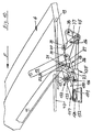
- Figure 10 shows a further embodiment according to the Invention, this embodiment of that according to figures 2 to 9 largely corresponds, so that largely the same Reference signs can be used.
- the top guide includes the front control arm 11 and the rear control arm 12, and it is with the convertible top guide the guide and Control for the parcel shelf 19 connected by Guide linkage is formed, of which the rear, with the guide linkage 12 connected to the guide linkage 18 is designated and the same training and arrangement as in Figures 2 through 9.
- the front guide linkage is in the assigned front guide link 11, but differs from Guide linkage 17 according to Figures 2 to 9 and is here designated 117 in total.
- the front linkage 117 is formed by a lever 150 which on the one hand in first guide point 22 with the console 21 of the rear shelf 19 connected and that at its other end via one Axis of rotation 128 in an elongated hole guide 151 body-fixed linkage 152 is guided and held.
- the Actuator, now designated 135, against the front Guide rod 117 supported this support in The scope of the invention is preferably coaxial with the axis of rotation 128 am Lever 150 takes place, that is, for example, not in more detail here shown against a pin that the axis of rotation 128th forms and via which the actuator 135 and the lever 150 in the slot guide 151 are supported together.
- the storage area according to FIG. 6 is the pin 133 So caught and held in the mouth 132 and at one of the Figure 6 functionally corresponding starting position for the Release of the pin 133 takes the mouth 132 a position one in which the mouth opening essentially towards is directed to the first guide point 22. Is this Position as the starting position is reached, the convertible top is 2 stored in the convertible top compartment 7 and the parcel shelf 19 analogous to the representation according to FIG. 7 in its second Closed position (ie in the position shown in Figure 9) transferred become. Since, as explained with reference to FIGS.
- the lever 150 is above the Pin 133 rotatably held coaxially to axis 15 and at the same time via the axis of rotation 128 in the slot guide 151 guided, the elongated hole guide 151 pivoting around the axis 15 does not allow, so that a 150 for the lever fixed, body-fixed position is given, with the result that the first guide point 22 forms a fixed axis around which the second guide point 23 is pivoted, namely to Swing direction of the top 2 in the front, closed Opposing position in its first closed position.
- the actuator 135 Because of the actuator 135 also the changeover between the two end positions in the elongated hole guide 151 only in connection with the Swiveling the rear shelf 19 between the open position and the second closed position or the second Closed positions of the open position has been made by the slot guide 151 does not give any degree of freedom adverse effects on the management of the convertible top 2 between its closed and open position as well as the fuse of the top 2 in these positions.
- an additional one is also possible Locking or securing for the axis of rotation 128 in the Slot guide 151 in each of their end positions to be provided, although the actuator 135, which is preferred by an actuating cylinder is formed, in turn can be locked accordingly.
- Such surveillance can be done directly or indirectly, for example by Detect the position of the top, or by using the lever 25 or 150 at least one end stop is assigned or also via appropriate sensors.
- Such surveillance the functional safety could in particular Vehicles with lower torsional stiffness are advisable, if these vehicles are parked on uneven terrain.
- the invention is characterized in that the Parcel shelf with the entire kinematics without additional tax expenditure completely and with considerable residual force in their respective start or end position is moved, the Weight of the convertible top under such a control is used in an advantageous manner to the total effort to reduce.
- Figure 3 attached for understanding the invention serves not the purpose, the correct allocation of the individual Handlebars and levers of the guides for the convertible top and parcel shelf to illustrate according to Figures 2 and 4 to 9, but rather only their functional interaction. Accordingly, those shown in this figure are Size relationships by no means to scale, just as little as the position of the parts relative to each other the actual, constructive position corresponds.
Landscapes
- Engineering & Computer Science (AREA)
- Mechanical Engineering (AREA)
- Vehicle Step Arrangements And Article Storage (AREA)
- Extensible Doors And Revolving Doors (AREA)
Claims (20)
- Plage arrière pour véhicules à capote (2) rabattable et équipés d'un compartiment à capote (7) qui reçoit la capote (2) ouverte rangée, laquelle peut être transférée d'une première position de fermeture définie lorsque la capote (2) est fermée vers une deuxième position de fermeture, décalée dans le sens longitudinal du véhicule (1) définie lorsque la capote (2) est ouverte et rangée dans le compartiment à capote (7) en passant par une position d'ouverture, caractérisée en ce que la plage arrière (19), en rapport avec ses positions de fermeture, présente deux points de guidage (22, 23) qui se trouvent du côté du compartiment à capote et qui sont espacés transversalement par rapport au plan de la plage arrière (19), dont le premier point de guidage (22), pendant la phase d'ouverture de la capote (2), constitue un axe de rotation pour l'autre, deuxième point de guidage (23) qui peut pivoter en direction du décalage longitudinal de la plage arrière (19), et le deuxième point de guidage (23), qui peut pivoter autour du premier point de guidage (22) lorsque la capote (2) est déposée afin de transférer la plage arrière (19) dans sa deuxième position de fermeture, constitue l'axe de rotation décalé dans le sens longitudinal pour le premier point de guidage (22).
- Plage arrière selon la revendication 1, caractérisée en ce que les points de guidage (22, 23) dans leur fonction d'axe de rotation sont à chaque fois fixés dans leur position et subissent un guidage forcé mécanique en fonction du guidage de la capote (2).
- Plage arrière selon la revendication 1 ou 2, caractérisée en ce que les points de guidage (22, 23), rapportés à la plage arrière fermée (19), sont décalés l'un par rapport à l'autre dans le sens longitudinal du véhicule et que parmi les points de guidage (22, 23), rapportés à la première position de fermeture de la plage arrière (19), le premier point de guidage (22) constitue un point de guidage supérieur plus proche de la plage arrière (19) qui est décalé dans le sens longitudinal entre la première et la deuxième position de fermeture de la plage arrière (19) par rapport au deuxième point de guidage (23) inférieur, plus éloigné de la plage arrière (19).
- Plage arrière selon une ou plusieurs des revendications précédentes, caractérisée en ce que, rapporté à une capote rabattable munie de deux bras articulés de guidage (11, 12) couplés entre eux et pivotant autour d'axes de rotation (15, 16) fixes sur la carrosserie et espacés dans le sens longitudinal du véhicule, chacun des points de guidage (22, 23) est à chaque fois associé à une tige de guidage (17, 18 ou 117, 18) commandée par le biais de l'un des bras articulés de guidage (11, 12).
- Plage arrière selon la revendication 4, caractérisée en ce que parmi les bras articulés de guidage (11, 12) espacés dans le sens longitudinal du véhicule (1), celui qui se trouve à l'avant agit conjointement avec la tige de guidage avant (17 ou 117) qui est reliée avec la plage arrière (19) dans le premier point de guidage (22).
- Plage arrière selon la revendication 4 ou 5, caractérisée en ce que parmi les bras articulés de guidage (11, 12) espacés dans le sens longitudinal du véhicule, celui qui se trouve à l'arrière agit conjointement avec la tige de guidage arrière (18) qui est reliée avec la plage arrière (19) dans le deuxième point de guidage (23).
- Plage arrière selon l'une des revendications 4 à 6, caractérisée en ce qu'une tige de guidage (17 ou 18) est constituée d'une paire de leviers (24, 25 ou 26, 27) dont l'un des leviers (25 ou 26) présente un axe de rotation fixe sur la carrosserie (28, 29).
- Plage arrière selon la revendication 7, caractérisée en ce que l'axe de rotation fixe sur la carrosserie (29) de la tige de guidage (18) reliée au bras articulé de guidage arrière (12), laquelle est reliée à la plage arrière (19) dans le deuxième point de guidage (23), est coïncident avec l'axe de rotation (22) constitué par le premier point de guidage (22) de la plage arrière (19) dans la première position de fermeture de la plage arrière (19).
- Plage arrière selon la revendication 8, caractérisée en ce que le deuxième point de guidage (23) de la plage arrière (19) est associé au levier (26) logé sur l'axe de rotation fixe sur la carrosserie (29) de la tige de guidage (18) reliée au bras articulé de guidage arrière (12) et que le levier (26) logé sur l'axe de rotation fixe sur la carrosserie (29) est fixé de manière articulée en son extrémité opposée à cet axe de rotation (29) avec le levier (27) relié au bras articulé de guidage arrière (12) de telle manière que, rapporté à la première position de fermeture de la plage arrière (19), les deux leviers (26, 27) de la tige de guidage (18) reliée au bras articulé de guidage arrière (12) s'étendent en direction de l'avant du véhicule.
- Plage arrière selon une ou plusieurs des revendications 5 à 9, caractérisée en ce que le levier (25) qui peut pivoter autour d'un axe de rotation fixe sur la carrosserie (28) est fixé de manière articulée dans la zone de l'une des extrémités de la tige de guidage (17) associée au bras articulé de guidage avant (11) à l'autre levier (24) de cette tige de guidage (17), lequel est relié à celle-ci dans le premier point de guidage (22) de la plage arrière (19) et peut être bloqué dans la zone de son autre extrémité par le bras articulé de guidage avant (11) en fonction de la position de basculement de celui-ci.
- Plage arrière selon une ou plusieurs des revendications 4 à 9, caractérisée en ce que la tige de guidage (117) associée au bras articulé de guidage avant (11) qui est relié à la plage arrière (19) dans le premier point de guidage (22), peut être décalée de manière limitée par le biais du mécanisme de positionnement (135) dans le sens du fonctionnement du mécanisme de positionnement (135) au niveau de son articulation du côté de la carrosserie (axe de rotation 128) en fonction de la position de rotation prédéfinie de la capote (2).
- Plage arrière selon la revendication 11, caractérisée en ce que l'articulation du côté de la carrosserie (axe de rotation 128) de la tige de guidage avant (117) est constituée par un axe de rotation (128) qui peut être décalé dans le sens du fonctionnement du mécanisme de positionnement (135), lequel est maintenu dans un guide longitudinal du côté de la carrosserie, plus précisément un guide à trou oblong (151).
- Plage arrière selon l'une des revendications 11 ou 12, caractérisée en ce que la tige de guidage (117) reliée au bras articulé de guidage avant (11) est constituée d'un levier (150) qui est relié à la plage arrière (19) dans le premier point de guidage (22) et qui peut être saisi entre l'articulation dans le premier point de guidage (22) et son articulation du côté de la carrosserie (axe de rotation 128), plus précisément dans sa zone centrale longitudinale avec le bras articulé de guidage avant (11) par le biais d'un dispositif d'accouplement (fourche de réception 132) qui se trouve dans la zone de son axe de rotation côté carrosserie (15).
- Plage arrière selon la revendication 10, caractérisée en ce que le bras articulé de guidage avant (11) présente dans la zone de son axe de rotation côté carrosserie (15) un dispositif d'accouplement (fourche de réception 32) par le biais duquel le levier (25) pivotant autour de l'axe de rotation côté carrosserie (28) de la tige de guidage avant (17) peut être saisi dans la zone en fin de chaíne correspondante.
- Plage arrière selon l'une des revendications 13 ou 14, caractérisée en ce que le dispositif d'accouplement est constitué par une fourche de réception (32 ou 132).
- Plage arrière selon la revendication 15, caractérisée en ce que la fourche de réception (32 ou 132) libère le levier (25 ou 150) pouvant être saisi par le biais du dispositif d'accouplement et pouvant être bloqué par rapport à l'axe de rotation (15) du bras articulé de guidage avant (11) lorsque la capote (2) est rangée dans le compartiment à capote (7).
- Plage arrière selon la revendication 16, caractérisée en ce qu'avec une tige de guidage (17) pivotante autour d'un axe de rotation (28) fixe du véhicule, laquelle est constituée par la paire de leviers (24, 25), la libération de liaison entre le deuxième levier (25) et le bras articulé de guidage avant (11) correspond à un sens de basculement de la plage arrière (19) autour du deuxième point de guidage (23) faisant office d'axe de rotation en direction de sa deuxième position de fermeture.
- Plage arrière selon la revendication 16, caractérisée en ce qu'avec une tige de guidage (117), laquelle est constituée d'un levier (150) guidé de manière coulissante dans le guide à trou oblong (151), la libération de la liaison entre ce levier (150) et le bras articulé de guidage avant (11) correspond pour l'essentiel à un décalage de ce levier (150) en direction du décalage longitudinal de la plage arrière (19) entre sa première et sa deuxième position de fermeture.
- Plage arrière selon une ou plusieurs des revendications précédentes, caractérisée en ce que la plage arrière (19) peut être positionnée avec la capote à l'aide d'un mécanisme de positionnement commun (35 ou 135), lequel est constitué d'un élément de positionnement à longueur variable, plus précisément un vérin de positionnement, qui est disposé entre le bras articulé de guidage arrière (12) et le levier (25 ou 150) logé du côté de la carrosserie de la tige de guidage (17 ou 117) associée au bras articulé de guidage avant (11).
- Plage arrière selon la revendication 19, caractérisée en ce que le bras articulé de guidage arrière (12) et la tige de guidage (17) constituée d'une paire de leviers (24, 25) et associée au bras articulé de guidage avant (11) présentent chacun le même sens de rotation par rapport à leurs axes de rotation côté carrosserie (16, 28) lors du positionnement par le biais du mécanisme de positionnement commun (35).
Applications Claiming Priority (2)
| Application Number | Priority Date | Filing Date | Title |
|---|---|---|---|
| DE19910228 | 1999-03-09 | ||
| DE19910228A DE19910228C1 (de) | 1999-03-09 | 1999-03-09 | Hutablage für Fahrzeuge mit abklappbarem Verdeck |
Publications (3)
| Publication Number | Publication Date |
|---|---|
| EP1034979A2 EP1034979A2 (fr) | 2000-09-13 |
| EP1034979A3 EP1034979A3 (fr) | 2000-10-11 |
| EP1034979B1 true EP1034979B1 (fr) | 2002-12-04 |
Family
ID=7900172
Family Applications (1)
| Application Number | Title | Priority Date | Filing Date |
|---|---|---|---|
| EP00104877A Expired - Lifetime EP1034979B1 (fr) | 1999-03-09 | 2000-03-07 | Plage arrière pour vehicules avec capote pliante |
Country Status (2)
| Country | Link |
|---|---|
| EP (1) | EP1034979B1 (fr) |
| DE (2) | DE19910228C1 (fr) |
Families Citing this family (11)
| Publication number | Priority date | Publication date | Assignee | Title |
|---|---|---|---|---|
| DE10117767C2 (de) * | 2001-04-09 | 2003-07-31 | Karmann Gmbh W | Heckseitige Abdeckung für ein Cabriolet |
| DE10149228C2 (de) * | 2001-10-05 | 2003-10-23 | Cts Fahrzeug Dachsysteme Gmbh | Verstellbares Fahrzeugdach |
| DE10353129B4 (de) * | 2003-11-14 | 2005-11-24 | Daimlerchrysler Ag | Verdeck für ein Kraftfahrzeug |
| DE10356003B4 (de) * | 2003-11-27 | 2006-11-30 | Webasto Ag | Hutablage eines Cabriolets |
| DE102004024229A1 (de) * | 2004-05-15 | 2005-12-01 | Wilhelm Karmann Gmbh | Cabriolet-Fahrzeug |
| DE102005007432A1 (de) * | 2005-02-18 | 2006-03-30 | Daimlerchrysler Ag | Vorrichtung zur Arretierung eines Hebels |
| DE102005035271A1 (de) * | 2005-07-28 | 2006-11-16 | Daimlerchrysler Ag | Kraftfahrzeug |
| FR2892062B1 (fr) * | 2005-10-13 | 2012-12-21 | Heuliez | Element de toit rigide, toit et vehicule convertible correspondants |
| DE102006016853B4 (de) | 2006-04-07 | 2008-01-03 | Magna Car Top Systems Gmbh | Verstellbares Fahrzeugdach |
| DE102006057967B4 (de) * | 2006-12-08 | 2009-01-08 | Webasto Ag | Öffnungsfähiges Fahrzeugdach mit einer Viergelenkanordnung |
| DE102009056987A1 (de) | 2009-12-04 | 2010-07-29 | Daimler Ag | Verdeck für einen offenen Personenkraftwagen mit Maßnahmen zur Schallabdämmung |
Family Cites Families (7)
| Publication number | Priority date | Publication date | Assignee | Title |
|---|---|---|---|---|
| JPS6033691B2 (ja) * | 1978-05-31 | 1985-08-05 | 日産自動車株式会社 | 自動車用棚部材構造 |
| JPS6033692B2 (ja) * | 1981-05-27 | 1985-08-05 | 日産自動車株式会社 | 自動車のパツケ−ジル−ム用棚板装置 |
| DE3607944A1 (de) * | 1986-03-11 | 1987-09-17 | Opel Adam Ag | Kraftfahrzeug mit einem rollo |
| DE4445580C1 (de) * | 1994-12-20 | 1995-12-21 | Daimler Benz Ag | Hardtop-Fahrzeug |
| DE19613917C2 (de) * | 1996-04-06 | 1998-01-15 | Daimler Benz Ag | Abdeckanordnung für einen im Heckbereich eines Fahrzeugs angeordneten Verdeckkasten |
| DE19616972A1 (de) * | 1996-04-27 | 1997-10-30 | Bayerische Motoren Werke Ag | Fahrzeugdach mit mehreren Dachelementen |
| DE19635869C1 (de) * | 1996-09-04 | 1998-01-22 | Daimler Benz Ag | Klappverdeck für Fahrzeuge |
-
1999
- 1999-03-09 DE DE19910228A patent/DE19910228C1/de not_active Expired - Lifetime
-
2000
- 2000-03-07 EP EP00104877A patent/EP1034979B1/fr not_active Expired - Lifetime
- 2000-03-07 DE DE50000853T patent/DE50000853D1/de not_active Expired - Lifetime
Also Published As
| Publication number | Publication date |
|---|---|
| EP1034979A3 (fr) | 2000-10-11 |
| DE50000853D1 (de) | 2003-01-16 |
| DE19910228C1 (de) | 2000-11-30 |
| EP1034979A2 (fr) | 2000-09-13 |
Similar Documents
| Publication | Publication Date | Title |
|---|---|---|
| EP1197368B1 (fr) | Couvercle multi-pièce pour véhicule | |
| EP1497148B1 (fr) | Capote de cabriolet | |
| EP1242260B1 (fr) | Systeme de recouvrement en plusieurs parties pour l'espace de reception d'une capote | |
| DE10116613C1 (de) | Cabriolet-Fahrzeug | |
| DE10146267B4 (de) | Verdeck für ein Cabriolet-Fahrzeug | |
| EP1735171B1 (fr) | Cinematique de direction pour toit rigide de vehicule cabriolet | |
| WO2005070715A1 (fr) | Hayon d'un vehicule automobile | |
| EP1034979B1 (fr) | Plage arrière pour vehicules avec capote pliante | |
| EP1314601B1 (fr) | Toit ouvrant de véhicule avec une capote pliante | |
| DE10247725B4 (de) | Cabriolet-Fahrzeug mit versenkbarem Verdeck | |
| DE10258052A1 (de) | Verstellbares Fahrzeugdach für Cabriolet-Fahrzeuge | |
| WO2004037579A1 (fr) | Vehicule cabriolet | |
| EP0400376B1 (fr) | Dispositif de réglage à un toit pliant pour un véhicule automobile | |
| DE102004038221A1 (de) | Verdeck für ein Cabriolet-Fahrzeug | |
| DE10242502B4 (de) | Verstellbares Fahrzeugdach | |
| DE10337353B4 (de) | Cabriolet-Fahrzeug | |
| DE10229808A1 (de) | Verdeck für ein Cabriolet-Fahrzeug | |
| EP1916139A1 (fr) | Véhicule automobile doté d'une capote pouvant être rangée dans un compartiment de capote | |
| EP1897734B1 (fr) | Cabriolet | |
| DE102005006568B3 (de) | Heckseitige Heckdeckelanbindung für Cabriolet-Fahrzeuge | |
| DE60122080T2 (de) | Versenkbares Fahrzeugdach enthaltend zwei starre Teile miteinander verbunden durch eine Anordnung von Hebeln und Gestänge | |
| DE102004043127B3 (de) | Hardtop-Fahrzeugdach mit mindestens zwei starren Dachteilen | |
| WO2006079308A1 (fr) | Systeme de toit compose d'au moins trois parties de toit | |
| EP1679215A2 (fr) | Liaison arrière d'une porte de coffre de véhicule pour un cabriolet | |
| DE102009009594B4 (de) | Verdeck für ein Cabriolet-Fahrzeug |
Legal Events
| Date | Code | Title | Description |
|---|---|---|---|
| PUAI | Public reference made under article 153(3) epc to a published international application that has entered the european phase |
Free format text: ORIGINAL CODE: 0009012 |
|
| PUAL | Search report despatched |
Free format text: ORIGINAL CODE: 0009013 |
|
| AK | Designated contracting states |
Kind code of ref document: A2 Designated state(s): DE ES FR GB IT SE |
|
| AX | Request for extension of the european patent |
Free format text: AL;LT;LV;MK;RO;SI |
|
| AK | Designated contracting states |
Kind code of ref document: A3 Designated state(s): AT BE CH CY DE DK ES FI FR GB GR IE IT LI LU MC NL PT SE |
|
| AX | Request for extension of the european patent |
Free format text: AL;LT;LV;MK;RO;SI |
|
| 17P | Request for examination filed |
Effective date: 20001123 |
|
| AKX | Designation fees paid |
Free format text: DE ES FR GB IT SE |
|
| GRAH | Despatch of communication of intention to grant a patent |
Free format text: ORIGINAL CODE: EPIDOS IGRA |
|
| GRAH | Despatch of communication of intention to grant a patent |
Free format text: ORIGINAL CODE: EPIDOS IGRA |
|
| GRAA | (expected) grant |
Free format text: ORIGINAL CODE: 0009210 |
|
| AK | Designated contracting states |
Kind code of ref document: B1 Designated state(s): DE ES FR GB IT SE |
|
| PG25 | Lapsed in a contracting state [announced via postgrant information from national office to epo] |
Ref country code: IT Free format text: LAPSE BECAUSE OF FAILURE TO SUBMIT A TRANSLATION OF THE DESCRIPTION OR TO PAY THE FEE WITHIN THE PRESCRIBED TIME-LIMIT;WARNING: LAPSES OF ITALIAN PATENTS WITH EFFECTIVE DATE BEFORE 2007 MAY HAVE OCCURRED AT ANY TIME BEFORE 2007. THE CORRECT EFFECTIVE DATE MAY BE DIFFERENT FROM THE ONE RECORDED. Effective date: 20021204 Ref country code: GB Free format text: LAPSE BECAUSE OF FAILURE TO SUBMIT A TRANSLATION OF THE DESCRIPTION OR TO PAY THE FEE WITHIN THE PRESCRIBED TIME-LIMIT Effective date: 20021204 |
|
| REG | Reference to a national code |
Ref country code: GB Ref legal event code: FG4D Free format text: NOT ENGLISH |
|
| REF | Corresponds to: |
Ref document number: 50000853 Country of ref document: DE Date of ref document: 20030116 |
|
| PG25 | Lapsed in a contracting state [announced via postgrant information from national office to epo] |
Ref country code: SE Free format text: LAPSE BECAUSE OF FAILURE TO SUBMIT A TRANSLATION OF THE DESCRIPTION OR TO PAY THE FEE WITHIN THE PRESCRIBED TIME-LIMIT Effective date: 20030304 |
|
| GBV | Gb: ep patent (uk) treated as always having been void in accordance with gb section 77(7)/1977 [no translation filed] |
Effective date: 20021204 |
|
| PG25 | Lapsed in a contracting state [announced via postgrant information from national office to epo] |
Ref country code: ES Free format text: LAPSE BECAUSE OF FAILURE TO SUBMIT A TRANSLATION OF THE DESCRIPTION OR TO PAY THE FEE WITHIN THE PRESCRIBED TIME-LIMIT Effective date: 20030627 |
|
| ET | Fr: translation filed | ||
| PLBE | No opposition filed within time limit |
Free format text: ORIGINAL CODE: 0009261 |
|
| STAA | Information on the status of an ep patent application or granted ep patent |
Free format text: STATUS: NO OPPOSITION FILED WITHIN TIME LIMIT |
|
| 26N | No opposition filed |
Effective date: 20030905 |
|
| REG | Reference to a national code |
Ref country code: FR Ref legal event code: PLFP Year of fee payment: 17 |
|
| PGFP | Annual fee paid to national office [announced via postgrant information from national office to epo] |
Ref country code: FR Payment date: 20160321 Year of fee payment: 17 |
|
| PGFP | Annual fee paid to national office [announced via postgrant information from national office to epo] |
Ref country code: DE Payment date: 20160330 Year of fee payment: 17 |
|
| REG | Reference to a national code |
Ref country code: DE Ref legal event code: R119 Ref document number: 50000853 Country of ref document: DE |
|
| REG | Reference to a national code |
Ref country code: FR Ref legal event code: ST Effective date: 20171130 |
|
| PG25 | Lapsed in a contracting state [announced via postgrant information from national office to epo] |
Ref country code: FR Free format text: LAPSE BECAUSE OF NON-PAYMENT OF DUE FEES Effective date: 20170331 Ref country code: DE Free format text: LAPSE BECAUSE OF NON-PAYMENT OF DUE FEES Effective date: 20171003 |