EP1034979B1 - Rear window shelf for vehicles with folding top - Google Patents
Rear window shelf for vehicles with folding top Download PDFInfo
- Publication number
- EP1034979B1 EP1034979B1 EP00104877A EP00104877A EP1034979B1 EP 1034979 B1 EP1034979 B1 EP 1034979B1 EP 00104877 A EP00104877 A EP 00104877A EP 00104877 A EP00104877 A EP 00104877A EP 1034979 B1 EP1034979 B1 EP 1034979B1
- Authority
- EP
- European Patent Office
- Prior art keywords
- guide
- rear window
- window shelf
- pivot
- lever
- Prior art date
- Legal status (The legal status is an assumption and is not a legal conclusion. Google has not performed a legal analysis and makes no representation as to the accuracy of the status listed.)
- Expired - Lifetime
Links
Images


Classifications
-
- B—PERFORMING OPERATIONS; TRANSPORTING
- B60—VEHICLES IN GENERAL
- B60J—WINDOWS, WINDSCREENS, NON-FIXED ROOFS, DOORS, OR SIMILAR DEVICES FOR VEHICLES; REMOVABLE EXTERNAL PROTECTIVE COVERINGS SPECIALLY ADAPTED FOR VEHICLES
- B60J7/00—Non-fixed roofs; Roofs with movable panels, e.g. rotary sunroofs
- B60J7/08—Non-fixed roofs; Roofs with movable panels, e.g. rotary sunroofs of non-sliding type, i.e. movable or removable roofs or panels, e.g. let-down tops or roofs capable of being easily detached or of assuming a collapsed or inoperative position
- B60J7/12—Non-fixed roofs; Roofs with movable panels, e.g. rotary sunroofs of non-sliding type, i.e. movable or removable roofs or panels, e.g. let-down tops or roofs capable of being easily detached or of assuming a collapsed or inoperative position foldable; Tensioning mechanisms therefor, e.g. struts
- B60J7/14—Non-fixed roofs; Roofs with movable panels, e.g. rotary sunroofs of non-sliding type, i.e. movable or removable roofs or panels, e.g. let-down tops or roofs capable of being easily detached or of assuming a collapsed or inoperative position foldable; Tensioning mechanisms therefor, e.g. struts with a plurality of rigid plate-like elements or rigid non plate-like elements, e.g. with non-slidable, but pivotable or foldable movement
- B60J7/143—Non-fixed roofs; Roofs with movable panels, e.g. rotary sunroofs of non-sliding type, i.e. movable or removable roofs or panels, e.g. let-down tops or roofs capable of being easily detached or of assuming a collapsed or inoperative position foldable; Tensioning mechanisms therefor, e.g. struts with a plurality of rigid plate-like elements or rigid non plate-like elements, e.g. with non-slidable, but pivotable or foldable movement for covering the passenger compartment
- B60J7/145—Non-fixed roofs; Roofs with movable panels, e.g. rotary sunroofs of non-sliding type, i.e. movable or removable roofs or panels, e.g. let-down tops or roofs capable of being easily detached or of assuming a collapsed or inoperative position foldable; Tensioning mechanisms therefor, e.g. struts with a plurality of rigid plate-like elements or rigid non plate-like elements, e.g. with non-slidable, but pivotable or foldable movement for covering the passenger compartment at least two elements being folded in clamp-shell fashion
-
- B—PERFORMING OPERATIONS; TRANSPORTING
- B60—VEHICLES IN GENERAL
- B60J—WINDOWS, WINDSCREENS, NON-FIXED ROOFS, DOORS, OR SIMILAR DEVICES FOR VEHICLES; REMOVABLE EXTERNAL PROTECTIVE COVERINGS SPECIALLY ADAPTED FOR VEHICLES
- B60J7/00—Non-fixed roofs; Roofs with movable panels, e.g. rotary sunroofs
- B60J7/20—Vehicle storage compartments for roof parts or for collapsible flexible tops
- B60J7/202—Vehicle storage compartments for roof parts or for collapsible flexible tops being characterised by moveable cover parts for closing the gap between boot lid and rearmost seats
-
- B—PERFORMING OPERATIONS; TRANSPORTING
- B60—VEHICLES IN GENERAL
- B60R—VEHICLES, VEHICLE FITTINGS, OR VEHICLE PARTS, NOT OTHERWISE PROVIDED FOR
- B60R5/00—Compartments within vehicle body primarily intended or sufficiently spacious for trunks, suit-cases, or the like
- B60R5/04—Compartments within vehicle body primarily intended or sufficiently spacious for trunks, suit-cases, or the like arranged at rear of vehicle
- B60R5/044—Compartments within vehicle body primarily intended or sufficiently spacious for trunks, suit-cases, or the like arranged at rear of vehicle luggage covering means, e.g. parcel shelves
- B60R5/045—Compartments within vehicle body primarily intended or sufficiently spacious for trunks, suit-cases, or the like arranged at rear of vehicle luggage covering means, e.g. parcel shelves collapsible or transformable
Definitions
- the invention relates to a parcel shelf for vehicles with Hinged top according to the preamble of claim 1.
- Such parcel shelves are generally known.
- Vehicles with a folding top are available as convertibles or Roadster known, the top as a folding top or as Hard top can be formed.
- the top In the open state it is recorded in a so-called convertible top compartment, some of which lies between the interior of the vehicle and the trunk, partly, especially with hardtops, also parts of the trunk claimed.
- the convertible top is not closed on one Convertible top compartment lid attached, so it forms, for example following the trunk lid in the closed state part of the cover of the convertible top compartment, which against the Vehicle interior is covered by a parcel shelf that is opened to open and close the convertible top and the one opened when lowered into the convertible top compartment Convertible top, then, for example, to the trunk lid covers the remaining opening of the convertible top compartment. Solutions of this kind are known from practice.
- Foldable tops are automated and inclusive the associated convertible top compartment covers, such as also hat racks are controlled in their sequence so that none further intervention by an operator is required, so there are complicated mechanics and a high one Control effort.
- the invention has for its object for vehicles with Folding top according to the preamble of claim 1 to create a control for a parcel shelf that stands out is characterized by a simple working principle and the result in Integrate convertible top controls as part of overall kinematics is.
- the guide points assigned to the parcel shelf and Rotary axes enable control with motion sequences, which is not prone to dead spots and where one of the Drive for the convertible top independent, independent actuator may be dispensed with for the parcel shelf can.
- the solution according to the invention of the management of the parcel shelf over two, based on a lying hat cover in Height-spaced guide points that alternate serve as axes of rotation, makes opening and closing the Parcel shelf with simultaneous shift in the longitudinal direction with simple means possible, the drive for the Rotational movements and the longitudinal offset preferred in simpler Way can be done via the drive for the roof guide.
- the control and management of the parcel shelf is according to the invention constructively easy to control when the Guide points in their function as axes of rotation Form guide points, the required ones This has a positive effect on the turning and offset paths let the guide points within the scope of the invention in Longitudinal direction of the vehicle offset from each other become.
- the guide points preferably form based on the first, with the roof closed given closed position of the parcel shelf, the upper guide point a first guide point in this first closed position the parcel shelf in the direction of the longitudinal offset of the parcel shelf between the first and second closed position compared to the second, lower guide point is offset.
- This basic arrangement makes it possible to start from the the first closed position of the parcel shelf the first guide point first use as a fixed axis of rotation around which the second The guide point is pivoted while opening the cover, being the pivot for the second guide point at the same time an offset in the direction of the longitudinal offset the parcel shelf towards the second closed position. Becomes now the second guide point offset in the longitudinal direction used as a fixed axis of rotation, so with the closing movement a longitudinal offset for the parcel shelf the same connected.
- the movement of the convertible top or of it Guide links used with simple mechanical means be coordinated to the guide points of the parcel shelf relocate and initiate appropriate rotary movements.
- control of the invention Hat rack in connection with convertible top structures advantageous insert that have a four-jointed roof guide, in the two body-fixed, in the longitudinal direction of the Vehicle spaced axes of rotation for two pivotable and linked guide links are provided, if each of the guide points of the parcel shelf is one over one of the guide links controlled guide linkage is assigned.
- This release can depend on the position of the first control arm can be reached automatically if this according to the invention with the first guide point associated guide linkage cooperates such that this - based on a given position of the first Leadership - from his fixation on the first Control arm is released. If the fixation is released, it can
- the support of the convertible top control assigned actuator for example a working cylinder against this guide linkage can be used to the parcel shelf around its second guide point as a pivot axis to pivot, with the actuator under the Construction according to the invention for this adjustment of the Parcel shelf can maintain the same positioning direction that for the convertible top from its closed position in its open position, stored in the convertible top compartment, is necessary was.
- a control of the parcel shelf in a convertible top control integrate in a simple way, becoming too Let dead positions tend to avoid leading positions and with a common drive for controlling the convertible top and the parcel shelf can be worked.
- the hat rack control according to the invention also with the Convertible top control on both sides of the vehicle in the same Realize training easily because the solution according to the invention only a few additional articulation points compared to the body requires and is insensitive to tolerance.
- FIG. 1 shows a schematic representation of the rear Part of a vehicle 1 which has a convertible top 2 that is to be opened has, which is between the indicated here Windshield frame 3 and the rear provided Trunk cover 4 extends, the top 2 through a so-called hardtop is formed, which one to the Windshield frame 3 adjoining roof section 5 as well comprises a rear window part 6. Roof part 5 and rear window part 6 of the convertible top 2 are for opening the convertible top 2 in a convertible top compartment 7, which is essentially above the wheel section 8 between the vehicle interior and Trunk 9 extends, part of the trunk 9 is used by the top compartment 7.
- roof part 5 and rear window part 6 are as Forced guidance formed and by a four-bar transmission 10 formed, which is shown essentially only schematically is and a front guide link 11, one rear guide link 12 and a coupling 13 includes the guide link 11, 12, of which the guide link 11 is designed here as a two-armed handlebar body-fixed pivot axes are pivotable.
- Guide devices are, via roof part 5 and rear window part 6 connected, in a symmetrical arrangement on both Provided sides of the vehicle 1 and each include an actuator 14 by an actuating cylinder is illustrated.
- this longitudinal displacement takes place in connection with the opening and closing of the parcel shelf 19, as is the case with Sinking the top 2 in the top compartment 7 and at Extend the convertible top 2 from the convertible top compartment 7 is required. Further details and characteristics of the Known top construction according to Figure 1 result from DE 44 45 580 C1.
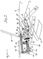
- a control of a rear shelf 19 in the manner according to the invention serve, based on a first embodiment, the figures 2 to 9, the rear shelf 19 being forcibly coupled to the convertible top 2 is arranged and accordingly when pivoting the top 2 is carried along.
- a common drive for convertible top 2 and parcel shelf 19 is provided, while maintaining its respective Direction of advance, which for the opening and the Closing process is opposite, the opening or closing process continuously.
- FIG 2 are of the four-link transmission assigned to the roof 10 only the front guide link 11 and the rear guide link 12 illustrated. From further Convertible top only the rear window part 6 is indicated schematically.
- the pivot axis for the front guide link 11 is with 15 and the pivot axis for the rear guide link 12 designated 16.
- Figure 3 additionally illustrates how the individual lever and handlebars of the guide rods 17 and 18 and of the four-bar linkage 10 in association with the rear shelf 19 whose drive and leadership work together.
- the parcel shelf 19 upstream - in the transition to the vehicle interior - is one Panel 43 by the parcel shelf 19 in its first The closed position is partially undershot.
- the rear shelf 19 is on its underside, i.e. their in the Closed positions of the top compartment 7 facing side 20, the Guide rods 17 and 18 associated with a console 21 provided which, spaced in the vertical direction, i.e. in different distance from the underside 20 of the rear shelf 19, a first guide point 22 and a second guide point 23, wherein in the first guide point 22 the front Guide linkage 17 and 23 in the second guide point rear guide linkage 18 connected to the console 21 is.
- the guide rods 17 and 18 are each by a Pair of levers formed, the levers of the guide linkage 17th with 24 and 25 and the lever of the guide linkage 18 with 26 and 27 are designated.
- each Pair of levers 17 and 18 is fixed to the body articulated, namely for the guide linkage 17 of the lever 25 and for the guide linkage 18 the lever 26. Die by the Body-specific articulation specific rotation axes are at 28 and 29 designated.
- levers 24 and 25 is the one around the body Axis of rotation 28 pivotable lever 25 as an angle lever formed, the arms 30 and 31 in the embodiment in opposite directions are diagonally upwards, with respect to the vehicle's longitudinal direction - the Forward direction is indicated in Figure 2 with F - rear lever arm 31 in the starting position when closed Hood according to Figure 2 at its free end over a mouth 32 of the front control arm 11 concentric to it Pivot axis 15 is held.
- the mouth 32 takes one Pin 33 projecting laterally from the arm 31 (see FIG. 3) and is open at the top so that the arm 31 is not at the bottom can swing out.
- At the free end of the other arm 30 of the Lever 25 is the lever 24 via an articulated axis 44 hinged.
- the lever 24 extends in the illustrated Starting position essentially parallel to the parcel shelf level 19 and is the arm 31 in the upper, first Guide point 22 with the console 21 of the rear shelf 19 connected.
- This first guide point 22 is in the starting position according to FIG Figure 2 coaxial to the body-fixed axis of rotation 29 of the lever 26 of the guide rod 18, which is in its longitudinal center Area in the second guide point 23 with the console 21 is connected and at the other end of the lever 27 in Point 46 is articulated, which in turn is at a pivot point 34 is connected to the rear guide arm 12.
- the rear guide link 12 is via the actuator 35 acted on for the top 2 and the parcel shelf 19th is effective together and by an actuating cylinder is formed.
- the hydraulic or pneumatic one Actuating cylinder of the actuator 35 acts on his Piston rod 36 through the mediation of a four-bar linkage rear guide link 12, the articulation on Guide link 12 via a support strut 37, which in turn at the end projecting beyond the pivot axis 16 of the rear control arm 12 is articulated in point 38 and the coaxial to the articulation 45 of the piston rod 36 a strut 39 fixed to the body at a pivot point 40 is rotatably supported.
- the actuator 35 is located opposite via the cylinder 41 supported in the articulation point 42 on the arm 30 of the lever 25, the in turn through storage on the body-fixed Axis of rotation 28 and the support in the jaw 32 fixed position is held until the actuator 35 moves together - With appropriate pivoting of the rear control arm 12 and the front carried over it Guide arm 11 in the direction of the stowed position of the Convertible top 2 in the convertible top compartment - the front guide link 11 reached a swivel position in which the opening of the mouth 32 approximately tangential to a concentric to the axis of rotation 28 Arch through the pivot axis 15 is such that on the Tensile force loading of the actuator 35 of the lever 25 den Threading the pin 33 out of the mouth 32.
- This removal position corresponds to the end position of the convertible top 2 in the convertible top compartment 7.
- the mass forces act in the direction of this end position of the convertible top 2 as soon as a limit position in the opening path of the Convertible top 2 is exceeded and it is for convertible top 2 in its storage position (end position) in the convertible top compartment 7 according to the invention, as shown in the embodiment, a Given stop position, so that the top 2 in the further Swiveling the rear shelf 19 in the sense of closing - Applying a tensile force via the actuator 35 - its Retains location and only the parcel shelf 19 in the sense of Relocation to its second closed position.
- FIGS. 2 to 9 The corresponding sequence is illustrated in FIGS. 2 to 9, with FIG. 9 showing the end position with the convertible top 2 deposited is illustrated. Is closing from this end position of the top 2 initiated, so there is an opposite Sequence, by extending the actuator 35 - at Support against the inertia of convertible top 2 - initially the parcel shelf 19 is raised ( Figure 8), in the course of further lifting (Figure 7) the lever 25 of the guide linkage 17 towards the mouth 32 of the still front guide link in the lowered rest position 11 is pivoted ( Figure 7) and finally the Pin 33 is threaded into the mouth 32 ( Figure 6). With the reverse procedure, this is again the starting position of the guide rod 17, now according to FIG.
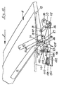
- Figure 10 shows a further embodiment according to the Invention, this embodiment of that according to figures 2 to 9 largely corresponds, so that largely the same Reference signs can be used.
- the top guide includes the front control arm 11 and the rear control arm 12, and it is with the convertible top guide the guide and Control for the parcel shelf 19 connected by Guide linkage is formed, of which the rear, with the guide linkage 12 connected to the guide linkage 18 is designated and the same training and arrangement as in Figures 2 through 9.
- the front guide linkage is in the assigned front guide link 11, but differs from Guide linkage 17 according to Figures 2 to 9 and is here designated 117 in total.
- the front linkage 117 is formed by a lever 150 which on the one hand in first guide point 22 with the console 21 of the rear shelf 19 connected and that at its other end via one Axis of rotation 128 in an elongated hole guide 151 body-fixed linkage 152 is guided and held.
- the Actuator, now designated 135, against the front Guide rod 117 supported this support in The scope of the invention is preferably coaxial with the axis of rotation 128 am Lever 150 takes place, that is, for example, not in more detail here shown against a pin that the axis of rotation 128th forms and via which the actuator 135 and the lever 150 in the slot guide 151 are supported together.
- the storage area according to FIG. 6 is the pin 133 So caught and held in the mouth 132 and at one of the Figure 6 functionally corresponding starting position for the Release of the pin 133 takes the mouth 132 a position one in which the mouth opening essentially towards is directed to the first guide point 22. Is this Position as the starting position is reached, the convertible top is 2 stored in the convertible top compartment 7 and the parcel shelf 19 analogous to the representation according to FIG. 7 in its second Closed position (ie in the position shown in Figure 9) transferred become. Since, as explained with reference to FIGS.
- the lever 150 is above the Pin 133 rotatably held coaxially to axis 15 and at the same time via the axis of rotation 128 in the slot guide 151 guided, the elongated hole guide 151 pivoting around the axis 15 does not allow, so that a 150 for the lever fixed, body-fixed position is given, with the result that the first guide point 22 forms a fixed axis around which the second guide point 23 is pivoted, namely to Swing direction of the top 2 in the front, closed Opposing position in its first closed position.
- the actuator 135 Because of the actuator 135 also the changeover between the two end positions in the elongated hole guide 151 only in connection with the Swiveling the rear shelf 19 between the open position and the second closed position or the second Closed positions of the open position has been made by the slot guide 151 does not give any degree of freedom adverse effects on the management of the convertible top 2 between its closed and open position as well as the fuse of the top 2 in these positions.
- an additional one is also possible Locking or securing for the axis of rotation 128 in the Slot guide 151 in each of their end positions to be provided, although the actuator 135, which is preferred by an actuating cylinder is formed, in turn can be locked accordingly.
- Such surveillance can be done directly or indirectly, for example by Detect the position of the top, or by using the lever 25 or 150 at least one end stop is assigned or also via appropriate sensors.
- Such surveillance the functional safety could in particular Vehicles with lower torsional stiffness are advisable, if these vehicles are parked on uneven terrain.
- the invention is characterized in that the Parcel shelf with the entire kinematics without additional tax expenditure completely and with considerable residual force in their respective start or end position is moved, the Weight of the convertible top under such a control is used in an advantageous manner to the total effort to reduce.
- Figure 3 attached for understanding the invention serves not the purpose, the correct allocation of the individual Handlebars and levers of the guides for the convertible top and parcel shelf to illustrate according to Figures 2 and 4 to 9, but rather only their functional interaction. Accordingly, those shown in this figure are Size relationships by no means to scale, just as little as the position of the parts relative to each other the actual, constructive position corresponds.
Description
Die Erfindung betrifft eine Hutablage für Fahrzeuge mit abklappbarem Verdeck gemäß dem Oberbegriff des Anspruches 1. Derartige Hutablagen sind allgemein bekannt.The invention relates to a parcel shelf for vehicles with Hinged top according to the preamble of claim 1. Such parcel shelves are generally known.
Fahrzeuge mit abklappbarem Verdeck sind als Cabriolets oder Roadster bekannt, wobei das Verdeck als Faltverdeck oder als Hardtop ausgebildet sein kann. Im geöffneten Zustand ist es in einem sogenannten Verdeckkasten aufgenommen, der teils zwischen Innenraum des Fahrzeuges und Kofferraum liegt, teils, so insbesondere bei Hardtops, auch Teile des Kofferraumes beansprucht.Vehicles with a folding top are available as convertibles or Roadster known, the top as a folding top or as Hard top can be formed. In the open state it is recorded in a so-called convertible top compartment, some of which lies between the interior of the vehicle and the trunk, partly, especially with hardtops, also parts of the trunk claimed.
Ist das Verdeck in geschlossenem Zustand nicht auf einen Verdeckkastendeckel aufgesetzt, so bildet es beispielsweise im Anschluß an den Kofferraumdeckel im geschlossenen Zustand einen Teil der Abdeckung des Verdeckkastens, der gegen den Fahrzeuginnenraum zu von einer Hutablage überdeckt wird, die zum Öffnen und Schließen des Verdeckes aufgeklappt wird und die, bei in den Verdeckkasten abgesenktem, geöffnetem Verdeck, anschließend beispielsweise an den Kofferraumdeckel die verbleibende Öffnung des Verdeckkastens überdeckt. Lösungen dieser Art sind aus der Praxis bekannt.If the convertible top is not closed on one Convertible top compartment lid attached, so it forms, for example following the trunk lid in the closed state part of the cover of the convertible top compartment, which against the Vehicle interior is covered by a parcel shelf that is opened to open and close the convertible top and the one opened when lowered into the convertible top compartment Convertible top, then, for example, to the trunk lid covers the remaining opening of the convertible top compartment. Solutions of this kind are known from practice.
Werden abklappbare Verdecke automatisiert und einschließlich der zugehörigen Verdeckkastenabdeckungen, wie beispielsweise auch Hutablagen in ihrem Ablauf so gesteuert, daß kein weiterer Eingriff einer Bedienungsperson erforderlich ist, so ergeben sich komplizierte Mechaniken und ein hoher Steuerungsaufwand. Foldable tops are automated and inclusive the associated convertible top compartment covers, such as also hat racks are controlled in their sequence so that none further intervention by an operator is required, so there are complicated mechanics and a high one Control effort.
Der Erfindung liegt die Aufgabe zugrunde, für Fahrzeuge mit abklappbarem Verdeck gemäß dem Oberbegriff des Anspruches 1 eine Steuerung für eine Hutablage zu schaffen, die sich durch ein einfaches Arbeitsprinzip auszeichnet und die dadurch in Verdecksteuerungen im Rahmen einer Gesamtkinematik zu integrieren ist. In die Verdecksteuerung integriert soll die Hutablage in Abstimmung auf die Kinematik des Verdeckes zwischen ihren den Endstellungen des Verdeckes - geschlossen und offen - entsprechenden Endstellung einen Bewegungsablauf haben, der sich konstruktiv einfach beherrschen läßt, bevorzugt den Einsatz eines gemeinsamen Stellantriebes ermöglicht, und insbesondere nicht zu Beeinträchtigungen der Verdecksteuerung führt.The invention has for its object for vehicles with Folding top according to the preamble of claim 1 to create a control for a parcel shelf that stands out is characterized by a simple working principle and the result in Integrate convertible top controls as part of overall kinematics is. The should be integrated in the convertible top control Parcel shelf in coordination with the kinematics of the soft top between their end positions of the top - closed and open - corresponding end position a sequence of movements have who can be easily controlled constructively, prefers the use of a common actuator enables, and in particular not to impair the Convertible top control leads.
Erreicht wird dies mit einer Hutablage gemäß dem Anspruch 1, wobei die der Hutablage zugeordneten Führungspunkte und Drehachsen eine Steuerung mit Bewegungsabläufen ermöglichen, die nicht zu Totpunkten neigt und bei der auf einen vom Antrieb für das Verdeck unabhängigen, eigenständigen Stellantrieb für die Hutablage gegebenenfalls verzichtet werden kann. Die erfindungsgemäße Lösung der Führung der Hutablage über zwei, bezogen auf eine liegende Hutabdeckung in Höhenrichtung beabstandete Führungspunkte, die abwechselnd als Drehachsen dienen, macht das Öffnen und Schließen der Hutablage bei gleichzeitiger Verlagerung in Längsrichtung mit einfachen Mitteln möglich, wobei der Antrieb für die Drehbewegungen und den Längsversatz bevorzugt in einfacher Weise über den Antrieb für die Verdeckführung erfolgen kann.This is achieved with a parcel shelf according to claim 1, the guide points assigned to the parcel shelf and Rotary axes enable control with motion sequences, which is not prone to dead spots and where one of the Drive for the convertible top independent, independent actuator may be dispensed with for the parcel shelf can. The solution according to the invention of the management of the parcel shelf over two, based on a lying hat cover in Height-spaced guide points that alternate serve as axes of rotation, makes opening and closing the Parcel shelf with simultaneous shift in the longitudinal direction with simple means possible, the drive for the Rotational movements and the longitudinal offset preferred in simpler Way can be done via the drive for the roof guide.
Die erfindungsgemäße Steuerung und Führung der Hutablage ist dann konstruktiv besonders einfach beherrschbar, wenn die Führungspunkte in ihrer Funktion als Drehachsen lagefeste Führungspunkte bilden, wobei sich die jeweils erforderlichen Dreh- und Versatzwege konstruktiv gut dadurch beeinflussen lassen, daß die Führungspunkte im Rahmen der Erfindung in Längsrichtung des Fahrzeuges gegeneinander versetzt angeordnet werden.The control and management of the parcel shelf is according to the invention constructively easy to control when the Guide points in their function as axes of rotation Form guide points, the required ones This has a positive effect on the turning and offset paths let the guide points within the scope of the invention in Longitudinal direction of the vehicle offset from each other become.
Bevorzugt bildet im Rahmen der Erfindung von den Führungspunkten, bezogen auf die erste, bei geschlossenem Verdeck gegebene Schließlage der Hutablage, der obere Führungspunkt einen ersten Führungspunkt, der in dieser ersten Schließlage der Hutablage in Richtung des Längsversatzes der Hutablage zwischen erster und zweiter Schließlage gegenüber dem zweiten, unteren Führungspunkt versetzt ist.Within the scope of the invention, the guide points preferably form based on the first, with the roof closed given closed position of the parcel shelf, the upper guide point a first guide point in this first closed position the parcel shelf in the direction of the longitudinal offset of the parcel shelf between the first and second closed position compared to the second, lower guide point is offset.
Diese Grundanordnung macht es möglich, ausgehend von der ersten Schließlage der Hutablage den ersten Führungspunkt zunächst als lagefeste Drehachse zu nutzen, um die der zweite Führungspunkt unter Öffnen des Deckels verschwenkt wird, wobei sich durch die Verschwenkung für den zweiten Führungspunkt gleichzeitig ein Versatz in Richtung des Längsversatzes der Hutablage zur zweiten Schließlage hin ergibt. Wird nunmehr der in Längsrichtung versetzte zweite Führungspunkt als lagefeste Drehachse genutzt, so ist mit der Schließbewegung für die Hutablage gleichzeitig ein Längsversatz derselben verbunden.This basic arrangement makes it possible to start from the the first closed position of the parcel shelf the first guide point first use as a fixed axis of rotation around which the second The guide point is pivoted while opening the cover, being the pivot for the second guide point at the same time an offset in the direction of the longitudinal offset the parcel shelf towards the second closed position. Becomes now the second guide point offset in the longitudinal direction used as a fixed axis of rotation, so with the closing movement a longitudinal offset for the parcel shelf the same connected.
Da die Überführung des Verdeckes aus der geschlossenen Lage in die Ablagestellung eine Verlagerung des Verdeckes in der gleichen Richtung bedingt wie die Überführung der Hutablage von der ersten in die zweite Schließstellung, kann erfindungsgemäß die Bewegung des Verdeckes bzw. von dessen Führungslenkern mit einfachen mechanischen Mitteln genutzt werden, um die Führungspunkte der Hutablage koordiniert zu verlagern und entsprechende Drehbewegungen einzuleiten.Because the convertible top is moved from the closed position in the storage position a shift of the top in the same direction as the transfer of the parcel shelf from the first to the second closed position according to the invention, the movement of the convertible top or of it Guide links used with simple mechanical means be coordinated to the guide points of the parcel shelf relocate and initiate appropriate rotary movements.
Insbesondere läßt sich die erfindungsgemäße Steuerung einer Hutablage in Verbindung mit Verdeckkonstruktionen vorteilhaft einsetzen, die eine viergelenkartige Verdeckführung aufweisen, bei der zwei karosseriefeste, in Längsrichtung des Fahrzeuges beäbstandete Drehachsen für zwei verschwenkbare und miteinander gekoppelte Führungslenker vorgesehen sind, wenn jedem der Führungspunkte der Hutablage jeweils ein über einen der Führungslenker angesteuertes Führungsgestänge zugeordnet wird.In particular, the control of the invention Hat rack in connection with convertible top structures advantageous insert that have a four-jointed roof guide, in the two body-fixed, in the longitudinal direction of the Vehicle spaced axes of rotation for two pivotable and linked guide links are provided, if each of the guide points of the parcel shelf is one over one of the guide links controlled guide linkage is assigned.
Von den in Längsrichtung des Fahrzeuges beabstandeten Führungslenkern wirkt zweckmäßigerweise der vordere mit dem Führungsgestänge zusammen, das dem ersten Führungspunkt zugeordnet ist, der in Richtung des Längsversatzes der Hutablage zwischen der ersten und der zweiten Schließlage gegenüber dem zweiten Führungspunkt der Hutablage versetzt ist, so daß durch Blockieren dieses Führungsgestänges der erste Führungspunkt zur lagefesten Drehachse wird. Diese Blockierung kann im Rahmen der Erfindung in einfacher Weise in Abhängigkeit von der Stellung des vorderen Führungslenkers erreicht werden. Wird der zweite, rückwärtige Führungslenker der Verdeckführung über ein entsprechendes Führungsgestänge mit dem zweiten Führungspunkt der Hutablage gekoppelt, so kann in einfacher Weise die Schwenkbewegung des zweiten Führungslenkers in eine entsprechende Drehbewegung der Hutablage umgesetzt werden, wobei eine dem abgelegten Verdeck entsprechende Endlage des zweiten Führungslenkers, in der dieser nach hinten in Richtung auf den Kofferraum in den Verdeckkasten abgeklappt ist, gleichzeitig zu einer Festlage für den zweiten Führungspunkt führt, in der dieser eine Drehachse für die Hutablage bilden kann, um die die Hutablage nach Freigabe des ersten Führungspunktes schwenken kann.Of those spaced in the longitudinal direction of the vehicle Leadership conveniently acts the front with the Guide rods together, which is the first guide point is assigned to the in the direction of the longitudinal offset Parcel shelf between the first and the second closed position offset from the second guide point of the parcel shelf is so that by blocking this guide linkage first guide point becomes the fixed axis of rotation. This Blocking can be done in a simple manner within the scope of the invention depending on the position of the front control arm can be achieved. Becomes the second, rear control arm the convertible top guide via a corresponding guide linkage coupled with the second guide point of the parcel shelf, see above can easily pivot the second Leadership in a corresponding rotational movement of the Rear parcel shelf are implemented, one being the stored hood corresponding end position of the second control arm, in the this back towards the trunk in the Convertible top compartment is folded down at the same time to a fixed position leads for the second guide point, in which this one Axis of rotation for the parcel shelf can form around which the parcel shelf after the first guide point has been released.
Diese Freigabe kann in Abhängigkeit von der Stellung des ersten Führungslenkers selbsttätig erreicht werden, wenn dieser erfindungsgemäß mit dem dem ersten Führungspunkt zugeordneten Führungsgestänge derart zusammenwirkt, daß dieses - bezogen auf eine vorgegebene Lage des ersten Führungslenkers - aus seiner Fixierung gegenüber dem ersten Führungslenker gelöst wird. Ist die Fixierung gelöst, so kann erfindungsgemäß die Abstützung des der Verdecksteuerung zugeordneten Stellantriebes, beispielsweise eines Arbeitszylinders gegen dieses Führungsgestänge genutzt werden, um die Hutablage um deren zweiten Führungspunkt als Schwenkachse zu verschwenken, wobei der Stellantrieb im Rahmen der erfindungsgemäßen Konstruktion für diese Verstellung der Hutablage die gleiche Stellrichtung beibehalten kann, die für die Umstellung des Verdeckes aus seiner geschlossenen Lage in seine geöffnete, im Verdeckkasten abgelegte Lage notwendig war.This release can depend on the position of the first control arm can be reached automatically if this according to the invention with the first guide point associated guide linkage cooperates such that this - based on a given position of the first Leadership - from his fixation on the first Control arm is released. If the fixation is released, it can According to the invention, the support of the convertible top control assigned actuator, for example a working cylinder against this guide linkage can be used to the parcel shelf around its second guide point as a pivot axis to pivot, with the actuator under the Construction according to the invention for this adjustment of the Parcel shelf can maintain the same positioning direction that for the convertible top from its closed position in its open position, stored in the convertible top compartment, is necessary was.
Während bei der Verstellbewegung für das Verdeck der Stellantrieb gegen das blockierte erste Führungsgestänge abgestützt war, also einen dem Führungsgestänge zugeordneten Festpunkt hatte, und das Verdeck unter der Wirkung seiner Massekräfte, oder zumindest unterstützt durch diese in seine Ablagestellung abgesenkt wird, ist nunmehr der Festpunkt dem abgelegten Verdeck bzw. dessen rückwärtigem Führungslenker zugeordnet, wobei die vergleichsweise geringen Verstellkräfte für die Verlagerung der Hutablage in ihre zweite Schließlage durch die Massekräfte des Verdeckes als Reaktionskräfte abgestützt werden können, oder auch durch die Abstützung des Verdeckes in seiner Ablagestellung, also eine Anschlagstellung des Verdeckes, so daß keine zusätzliche Verriegelung erforderlich ist.While the adjustment movement for the convertible top Actuator against the blocked first guide linkage was supported, i.e. one associated with the guide linkage Had fixed point, and the hood under the effect of his Inertial forces, or at least supported by this in his Storage position is lowered, is now the benchmark stored convertible top or its rear control arm assigned, the comparatively low adjustment forces for moving the parcel shelf to its second closed position through the inertial forces of the hood as reaction forces can be supported, or by supporting the Convertible top in its storage position, i.e. a stop position of the top, so that no additional locking is required.
Mit der erfindungsgemäßen Ausgestaltung einer Hutablage läßt sich somit eine Steuerung der Hutablage in eine Verdecksteuerung in einfacher Weise integrieren, wobei sich zu Totlagen neigende Führungsstellungen vermeiden lassen und mit einem gemeinsamen Antrieb für die Steuerung des Verdeckes und der Hutablage gearbeitet werden kann. Insbesondere läßt sich die erfindungsgemäße Steuerung der Hutablage auch mit der Verdecksteuerung auf den beiden Fahrzeugseiten in gleicher Ausbildung leicht realisieren, da die erfindungsgemäße Lösung nur wenige zusätzliche Anlenkpunkte gegenüber der Karosserie erforderlich macht und toleranzunempfindlich ist.With the design of a parcel shelf according to the invention thus a control of the parcel shelf in a convertible top control integrate in a simple way, becoming too Let dead positions tend to avoid leading positions and with a common drive for controlling the convertible top and the parcel shelf can be worked. In particular, the hat rack control according to the invention also with the Convertible top control on both sides of the vehicle in the same Realize training easily because the solution according to the invention only a few additional articulation points compared to the body requires and is insensitive to tolerance.
Weitere Merkmale der Erfindung ergeben sich aus den Ansprüchen. Ferner wird die Erfindung nachfolgend anhand von Ausführungsbeispielen näher erläutert, wobei,
- Figur 1
- in stark schematisierter Darstellung einen Ausschnitt eines Fahrzeuges mit einem abklappbaren Verdeck zeigt, dessen Verdeckführung nur in den Grundzügen gezeigt ist,
- Figur 2
- eine vereinfachte und schematisierte Seitenansicht einer Steuerung einer Hutablage gemäß Figur 1 in einer ersten Ausführungsform und in Verbindung mit einer teilweise vereinfacht dargestellten Führung für ein als Hardtop ausgebildetes Verdeck in einer Grundstellung, in der das Verdeck geschlossen ist,
- Figur 3
- eine Schnittdarstellung, vergrößert, schematisiert und im Hinblick auf die Verdeutlichung der funktionalen Zusammenhänge abgewandelt, entsprechend der Schnittlinie III-III in Figur 2 durch die Steuerung der Hutablage gemäß Figur 2,
Figur 4- eine Übergangsphase, in der die Hutablage gemäß Figur 2 und das Verdeck mit den zugeordneten Führungs- und Antriebselementen bei halbgeöffnetem Verdeck dargestellt sind,
Figur 5- eine weitere Übergangsstellung, im Anschluß an die
Stellung gemäß
Figur 4 beim Öffnen des Verdeckes, wobei der angedeutete vordere Dachteil sich an der geöffneten Hutablage vorbeibewegt, Figur 6- eine weitere Übergangsstellung in der Steuerung der Hutablage gemäß Figur 2, wobei das Verdeck nunmehr seine Endlage im Verdeckkasten (Ablagestellung) des Fahrzeuges erreicht hat, so daß der Schließvorgang für die Hutablage durchgeführt werden muß,
Figur 7- der Beginn des Schließvorganges für die Hutablage gemäß Figur 2 mit Überführung der Hutablage in ihre zweite Schließstellung, wobei der Stellantrieb seine Bewegungsrichtung beibehält und die Steuerung der Hutablage aus ihrer Verriegelung gegenüber der Steuerung des Verdeckes gelöst wird,
- Figur 8
- eine weitere Zwischenstellung im Schließvorgang der Hutablage gemäß Figur 2 bei abgelegtem Verdeck,
- Figur 9
- die Endstellung der Hutablage gemäß Figur 2, in der die Hutablage den Zugang zum Verdeckkasten bei abgelegtem Verdeck überdeckt, und
Figur 10- bezogen auf eine der Darstellung gemäß Figur 2 entsprechende Lage eine weitere, im Rahmen der Erfindung liegende Ausgestaltung der Steuerung einer Hutablage.
- Figure 1
- shows in a highly schematic representation a section of a vehicle with a folding top, the top guide of which is only shown in the basic features,
- Figure 2
- 2 shows a simplified and schematic side view of a control system for a parcel shelf according to FIG. 1 in a first embodiment and in conjunction with a guide, shown in a partially simplified manner, for a convertible top designed as a hard top in a basic position in which the convertible top is closed,
- Figure 3
- 3 shows a sectional illustration, enlarged, schematic and modified with a view to clarifying the functional relationships, in accordance with the section line III-III in FIG. 2 by controlling the parcel shelf according to FIG. 2,
- Figure 4
- a transition phase in which the parcel shelf according to FIG. 2 and the convertible top with the associated guide and drive elements are shown with the convertible top half open,
- Figure 5
- a further transition position, following the position according to FIG. 4 when the convertible top is opened, the indicated front roof part moving past the opened rear parcel shelf,
- Figure 6
- a further transition position in the control of the parcel shelf according to Figure 2, wherein the top has now reached its end position in the top compartment (storage position) of the vehicle, so that the closing process for the parcel shelf must be carried out,
- Figure 7
- the beginning of the closing process for the parcel shelf according to FIG. 2 with transfer of the parcel shelf into its second closed position, the actuator maintaining its direction of movement and the control of the parcel shelf being released from its locking in relation to the control of the convertible top,
- Figure 8
- another intermediate position in the closing process of the parcel shelf according to FIG. 2 with the convertible top down,
- Figure 9
- the end position of the parcel shelf according to Figure 2, in which the parcel shelf covers the access to the convertible top compartment when the convertible top is down, and
- Figure 10
- based on a position corresponding to the representation according to FIG. 2, a further embodiment of the control system for a parcel shelf lying within the scope of the invention.
Figur 1 zeigt in schematisierter Darstellung den rückwärtigen
Teil eines Fahrzeuges 1, das ein zu öffnendes Verdeck 2
aufweist, welches sich zwischen dem hier angedeuteten
Windschutzscheibenrahmen 3 und der heckseitig vorgesehenen
Kofferraumabdeckung 4 erstreckt, wobei das Verdeck 2 durch
ein sogenanntes Hardtop gebildet ist, welches einen an den
Windschutzscheibenrahmen 3 anschließenden Dachteil 5 sowie
einen Rückfensterteil 6 umfaßt. Dachteil 5 und Rückfensterteil
6 des Verdeckes 2 sind zum öffnen des Verdeckes 2 in
einem Verdeckkasten 7 verstaubar, der sich im wesentlichen
oberhalb des Radausschnittes 8 zwischen Fahrzeuginnenraum und
Kofferraum 9 erstreckt, wobei ein Teil des Kofferraumes 9
durch den Verdeckkasten 7 in Anspruch genommen wird.Figure 1 shows a schematic representation of the rear
Part of a vehicle 1 which has a convertible top 2 that is to be opened
has, which is between the indicated here
Windshield frame 3 and the rear provided
Die Führung von Dachteil 5 und Rückfensterteil 6 ist als
Zwangsführung ausgebildet und durch ein Viergelenkgetriebe 10
gebildet, das im wesentlichen nur schematisiert dargestellt
ist und das einen vorderen Führungslenker 11, einen
rückwärtigen Führungslenker 12 sowie eine Koppel 13 umfaßt,
wobei die Führungslenker 11, 12, von denen der Führungslenker
11 hier als zweiarmiger Lenker ausgebildet ist, um
karosseriefeste Schwenkachsen verschwenkbar sind. Derartige
Führungseinrichtungen sind, über Dachteil 5 und Rückfensterteil
6 verbunden, in symmetrischer Anordnung auf beiden
Seiten des Fahrzeuges 1 vorgesehen und umfassen jeweils auch
einen Stellantrieb 14, der durch einen Stellzylinder
veranschaulicht ist.The management of
Wird das Verdeck 2 im Verdeckkasten 7 abgelegt, so bedingt
der Bewegungsablauf des Viergelenkgetriebes 10, daß in der
abgelegten Position der Rückfensterteil 6 auf dem Rücken
liegt, also mit seiner bei geschlossenem Verdeck dem
Fahrzeuginnenraum zugewandten Innenseite nach oben, und vom
Dachteil 5 in seiner Normalposition, also mit nach oben und
außen liegender Dachhaut überdeckt ist.If the convertible top 2 is placed in the convertible
Das Ein- und Ausfahren des Verdeckes 2 in bzw. aus dem
Verdeckkasten 7 bedingt eine nach oben offene Verdeckkastenöffnung,
die, im Gestaltungsbeispiel gemäß Figur 1, teilweise
durch die Kofferraumabdeckung 4 in deren geschlossenem
Zustand überdeckt ist, und teilweise durch eine in Figur 1
nicht dargestellte Hutablage - in den Figuren 2 bis 9 mit 19
bezeichnet -, wobei diese Hutablage 19, bezogen auf das
geschlossene Verdeck, den Freiraum zwischen der Innenraumrückwand
und dem Rückfensterteil 6 überdeckt. Bezogen auf
eine Ausgestaltung gemäß Figur 1 bedeutet dies, daß bei in
den Verdeckkasten 7 abgelegtem Verdeck 2 zwischen der
Hutablage 19, bezogen auf deren vorbeschriebene
Positionierung bei geschlossenem Verdeck 2, und der
geschlossenen Kofferraumabdeckung 4 ein Spalt verbleibt, der
zusätzlich überdeckt werden muß, wozu die Hutablage 19 im
Rahmen der erfindungsgemäßen Lösung längsverschieblich ist. The retraction and extension of the top 2 in or out of
Convertible
Erfindungsgemäß erfolgt diese Längsverschiebung in Verbindung
mit dem Öffnen und Schließen der Hutablage 19, wie dies beim
Versenken des Verdeckes 2 in den Verdeckkasten 7 und beim
Ausfahren des Verdeckes 2 aus dem Verdeckkasten 7
erforderlich ist. Weitere Einzelheiten und Merkmale der an
sich bekannten Verdeckkonstruktion gemäß Figur 1 ergeben sich
aus der DE 44 45 580 C1.According to the invention, this longitudinal displacement takes place in connection
with the opening and closing of the
Für die Erläuterung der Erfindung und das nähere Verständnis
einer Steuerung einer Hutablage 19 in erfindungsgemäßer Weise
dienen, bezogen auf eine erste Ausführungsform, die Figuren 2
bis 9, wobei die Hutablage 19 in Zwangskopplung zum Verdeck 2
angeordnet ist und bei Verschwenken des Verdeckes 2 entsprechend
mitgeführt wird. In Ausgestaltung der Erfindung ist
ein gemeinsamer Antrieb für Verdeck 2 und Hutablage 19
vorgesehen ist, der unter Beibehalt seiner jeweiligen
Vortriebsrichtung, die für den Öffnungs- und den
Schließvorgang entgegengesetzt ist, jeweils den Öffnungs-
bzw. Schließvorgang durchlaufend bewirkt.For the explanation of the invention and the closer understanding
a control of a
In Figur 2 sind von dem dem Dach zugeordneten Viergelenkgetriebe
10 nur der vordere Führungslenker 11 und der
rückwärtige Führungslenker 12 veranschaulicht. Vom weiteren
Verdeck ist nur der Rückfensterteil 6 schematisch angedeutet.In Figure 2 are of the four-link transmission assigned to the
Den Bestandteile des Viergelenkgetriebes 10 bildenden,
symmetrisch für beide Fahrzeugseiten vorgesehenen vorderen
Führungslenkern 11 und rückwärtigen Führungslenkern 12 sind,
wie in der schematisierten Darstellung gemäß Figur 2
erkennbar, jeweils karosseriefeste Schwenkachsen zugeordnet.
Die Schwenkachse für den vorderen Führungslenker 11 ist mit
15 und die Schwenkachse für den rückwärtigen Führungslenker
12 mit 16 bezeichnet. The components of the four-
Gekoppelt mit den Führungslenkern 11 und 12 sind jeweils
Führungsgestänge 17 und 18, die ihrerseits die Hutablage 19
steuern, welche in Figur 2 in ihrer bezogen auf das geschlossene
Verdeck 2 abgestimmten vorderen, ersten Schließlage
gezeigt ist, wobei vom Verdeck in Figur 2 nur der
Rückfensterteil 6 gezeigt ist, der im geschlossenen Zustand
des Verdeckes 2 mit seinen seitlichen Begrenzungen die C-Säule
des Fahrzeuges bildet. Die entsprechende, zweite
Schließlage der Hutablage 19 ist in Figur 9 veranschaulicht,
wobei der Vergleich der Figuren 2 und 9 zeigt, daß die zweite
Schließlage, die bei geöffnetem Verdeck gegeben ist, eine
nach hinten versetzte rückwärtige Schließlage ist, so daß die
Hutablage 19 in dieser zweiten Schließlage den Spaltbereich
im Zugang zum Verdeckkasten 7 überdecken kann, der bei
geschlossenem Verdeck 2 vom Rückfensterteil 6 abgedeckt und
ausgefüllt ist.Coupled with the guide links 11 and 12 are, respectively
Nachfolgend wird, bezogen auf das Ausführungsbeispiel gemäß
Figuren 2 bis 9, zunächst der grundsätzliche Aufbau der
Führungsgestänge 17 und 18 in Zuordnung zur Hutablage 19
beschrieben, wobei Figur 3 ergänzend veranschaulicht, wie die
einzelnen Hebel und Lenker der Führungsgestänge 17 und 18 und
des Viergelenkgetriebes 10 in Zuordnung zur Hutablage 19 zu
deren Antrieb und Führung zusammenwirken. Der Hutablage 19
vorgelagert - im Übergang zum Fahrzeuginnenraum - ist eine
Verkleidung 43, die von der Hutablage 19 in ihrer ersten
Schließlage teilweise untergriffen ist.In the following, based on the embodiment according to
Figures 2 to 9, first the basic structure of the
Die Hutablage 19 ist an ihrer Unterseite, d.h. ihrer in den
Schließlagen dem Verdeckkasten 7 zugewandten Seite 20, den
Führungsgestängen 17 und 18 zugeordnet mit einer Konsole 21
versehen, die, in Höhenrichtung beabstandet, d.h. in
verschiedenem Abstand zur Unterseite 20 der Hutablage 19,
einen ersten Führungspunkt 22 und einen zweiten Führungspunkt
23 aufweist, wobei im ersten Führungspunkt 22 das vordere
Führungsgestänge 17 und im zweiten Führungspunkt 23 das
rückwärtige Führungsgestänge 18 mit der Konsole 21 verbunden
ist. Die Führungsgestänge 17 und 18 sind jeweils durch ein
Hebelpaar gebildet, wobei die Hebel des Führungsgestänges 17
mit 24 und 25 und die Hebel des Führungsgestänges 18 mit 26
und 27 bezeichnet sind. Von den Hebeln 25, 24; 26, 27 jedes
Hebelpaares 17 und 18 ist jeweils einer karosseriefest
angelenkt, nämlich für das Führungsgestänge 17 der Hebel 25
und für das Führungsgestänge 18 der Hebel 26. Die durch die
karosseriefeste Anlenkung bestimmten Drehachsen sind mit 28
und 29 bezeichnet.The
Von den Hebeln 24 und 25 ist der um die karosseriefeste
Drehachse 28 schwenkbare Hebel 25 als Winkelhebel
ausgebildet, dessen Arme 30 und 31 im Ausführungsbeispiel in
entgegengesetzten Richtungen schräg nach oben verlaufen,
wobei der bezogen auf die Fahrzeuglängsrichtung - die
Vorwärtsfahrtrichtung ist in Figur 2 mit F angedeutet -
rückwärtige Hebelarm 31 in der Ausgangslage bei geschlossenem
Verdeck gemäß Figur 2 an seinem freien Ende über ein Fangmaul
32 des vorderen Führungslenkers 11 konzentrisch zu dessen
Schwenkachse 15 gehalten ist. Das Fangmaul 32 nimmt einen
seitlich vom Arm 31 abragenden Zapfen 33 (siehe Figur 3) auf
und ist nach oben offen, so daß der Arm 31 nicht nach unten
ausschwenken kann. Am freien Ende des anderen Armes 30 des
Hebels 25 ist der Hebel 24 über eine Gelenkachse 44
angelenkt. Der Hebel 24 erstreckt sich in der dargestellten
Ausgangslage im wesentlichen parallel zur Ebene der Hutablage
19 und ist den Arm 31 übergreifend im oberen, ersten
Führungspunkt 22 mit der Konsole 21 der Hutablage 19
verbunden.Of
Dieser erste Führungspunkt 22 liegt in der Ausgangslage gemäß
Figur 2 koaxial zur karosseriefesten Drehachse 29 des Hebels
26 des Führungsgestänges 18, der in seinem längsmittleren
Bereich im zweiten Führungspunkt 23 mit der Konsole 21
verbunden ist und an dessen anderem Ende der Hebel 27 im
Punkt 46 angelenkt ist, der seinerseits in einem Drehpunkt 34
mit dem rückwärtigen Führungslenker 12 verbunden ist.This
Der rückwärtige Führungslenker 12 ist über den Stellantrieb
35 beaufschlagt, der für das Verdeck 2 und die Hutablage 19
gemeinsam wirksam ist und der durch einen Stellzylinder
gebildet ist. Der hydraulisch oder pneumatisch beaufschlagte
Stellzylinder des Stellantriebes 35 beaufschlagt über seine
Kolbenstange 36 unter Vermittlung eines Viergelenkes den
rückwärtigen Führungslenker 12, wobei die Anlenkung am
Führungslenker 12 über eine Stützstrebe 37 erfolgt, die
ihrerseits am über die Schwenkachse 16 hinausragenden Ende
des rückwärtigen Führungslenkers 12 in Punkt 38 angelenkt ist
und die koaxial zur Anlenkung 45 der Kolbenstange 36 über
eine Haltestrebe 39 karosseriefest in einem Anlenkpunkt 40
drehbar abgestützt ist.The
Gegenüberliegend ist der Stellantrieb 35 über den Zylinder 41
im Anlenkpunkt 42 am Arm 30 des Hebels 25 abgestützt, der
seinerseits durch die Lagerung auf der karosseriefesten
Drehachse 28 und die Abstützung im Fangmaul 32 lagefest
gehalten ist, bis durch Zusammenfahren des Stellantriebes 35
- mit entsprechender Verschwenkung des rückwärtigen Führungslenkers
12 und des über diesen mitgenommenen vorderen
Führungslenkers 11 in Richtung auf die Verstaulage des
Verdeckes 2 im Verdeckkasten - der vordere Führungslenker 11
eine Schwenklage erreicht, in der die Öffnung des Fangmaules
32 etwa tangential zu einem zur Drehachse 28 konzentrischen
Bogen durch die Schwenkachse 15 liegt, derart, daß über die
Zugkraftbeanspruchung des Stellantriebes 35 der Hebel 25 den
Zapfen 33 aus dem Fangmaul 32 ausfädelt. The
Dieser Ausfädelposition, die in Figur 6 veranschaulicht ist,
entspricht die Endstellung des Verdeckes 2 im Verdeckkasten
7. In Richtung auf diese Endstellung wirken die Massekräfte
des Verdeckes 2, sobald eine Grenzlage im Öffnungsweg des
Verdeckes 2 überschritten ist, und es ist für das Verdeck 2
in seiner Ablagestellung (Endstellung) im Verdeckkasten 7
erfindungsgemäß, wie im Ausführungsbeispiel dargestellt, eine
Anschlagstellung gegeben, so daß das Verdeck 2 beim weiteren
Verschwenken der Hutablage 19 im Sinne des Schließens -
Aufbringen einer Zugkraft über den Stellantrieb 35 - seine
Lage beibehält und lediglich die Hutablage 19 im Sinne einer
Verlagerung in ihre zweite Schließstellung verlagert wird.
Ist diese erreicht, so sind über den Stellantrieb 35 beide
Verschwenkpartner - Hutablage 19 und Verdeck 2 - in ihrer
Endlage bei geöffnetem Verdeck 2 gehalten, wobei auch der
Hutablage 19 oder dem zugehörigen Führungsgestänge 17 ein
diese Endlage bestimmender Anschlag zweckmäßigerweise
zugeordnet sein kann, was hier nicht weiter dargestellt ist.This removal position, which is illustrated in FIG. 6,
corresponds to the end position of the convertible top 2 in the convertible
Bei der erfindungsgemäßen Lösung wird von dem Gedanken
Gebrauch gemacht, daß die höhenversetzte Lage des ersten
Führungspunktes 22 und des zweiten Führungspunktes 23 und
eine wechselseitige Nutzung dieser Führungspunkte als Drehachsen
Dreh- und Schwenkbewegungen der Hutablage 19
ermöglicht, wobei durch Verschwenken des einen der Führungspunkte,
hier des Führungspunktes 23 um den Führungspunkt 22
als Drehachse für den Führungspunkt 23 eine Ausgangslage als
Drehachse geschaffen werden kann, die bei durch die Drehung
um den ersten Führungspunkt 22 als Drehachse erreichter,
translatorisch versetzter Lage für den zweiten Führungspunkt
23 und dessen Nutzung als Drehachse zu einer Längsverschiebung
der Hutablage 19 in Verbindung mit deren
Verschwenken führt. In the solution according to the invention, the thought
Made use of the fact that the height offset position of the
Den entsprechenden Ablauf veranschaulichen die Figuren 2 bis
9, wobei mit Figur 9 die Endlage mit abgelegtem Verdeck 2
veranschaulicht ist. Wird aus dieser Endlage das Schließen
des Verdeckes 2 eingeleitet, so ergibt sich ein gegenläufiger
Ablauf, wobei durch Ausfahren des Stellantriebes 35 - bei
Abstützung gegen die Massekraft des Verdeckes 2 - zunächst
die Hutablage 19 angehoben wird (Figur 8), im Verlauf des
weiteren Anhebens (Figur 7) der Hebel 25 des Führungsgestänges
17 in Richtung auf das Fangmaul 32 des nach wie vor
in der abgesenkten Ruhelage befindlichen vorderen Führungslenkers
11 verschwenkt wird (Figur 7) und schließlich der
Zapfen 33 in das Fangmaul 32 eingefädelt wird (Figur 6).
Damit ist, bei umgekehrtem Ablauf, wiederum die Ausgangsstellung
des Führungsgestänges 17, nunmehr gemäß Figuren 6
bis 2 erreicht, in der über das Führungsgestänge 17 der erste
Führungspunkt 22 als Drehachse fixiert ist, um den der zweite
Führungspunkt 23 über den Hebel 26 des Führungsgestänges 18
geschwenkt wird, womit beim weiteren Ausfahren des
Stellantriebes 35 das Verdeck 2 aus dem Verdeckkasten 7
angehoben und in Schließrichtung verschwenkt wird. Hierbei
eilt die Schließbewegung des Verdeckes 2 der Schließbewegung
der Hutablage 19 bezogen auf deren Überführung in die erste
Schließlage (Figur 2) voraus.The corresponding sequence is illustrated in FIGS. 2 to
9, with FIG. 9 showing the end position with the convertible top 2 deposited
is illustrated. Is closing from this end position
of the top 2 initiated, so there is an opposite
Sequence, by extending the actuator 35 - at
Support against the inertia of convertible top 2 - initially
the
Figur 10 zeigt eine weitere Ausgestaltungsform gemäß der Erfindung, wobei diese Ausgestaltungsform jener gemäß Figuren 2 bis 9 weitgehend entspricht, so daß auch weitgehend gleiche Bezugszeichen Verwendung finden können. Insbesondere ist auch die Grundfunktion der erfindungsgemäßen Steuerung einer Hutablage gemäß Figuren 1 bis 9 bei der Ausgestaltungsform gemäß Figur 10 gegeben, weswegen auf die diesbezüglichen Ausführungen zu Figuren 2 bis 9 ausdrücklich Bezug genommen wird. Figure 10 shows a further embodiment according to the Invention, this embodiment of that according to figures 2 to 9 largely corresponds, so that largely the same Reference signs can be used. In particular, too the basic function of the control of a parcel shelf according to the invention according to Figures 1 to 9 in the embodiment according to Figure 10 given, why on the relevant statements expressly referred to Figures 2 to 9 becomes.
Analog zu den Figuren 2 bis 9 umfaßt die Verdeckführung den
vorderen Führungslenker 11 und den rückwärtigen Führungslenker
12, und es ist mit der Verdeckführung die Führung und
Steuerung für die Hutablage 19 verbunden, welche durch
Führungsgestänge gebildet ist, von denen das rückwärtige, mit
dem Führungslenker 12 verbundene Führungsgestänge mit 18
bezeichnet ist und die gleiche Ausbildung und Anordnung wie
in Figuren 2 bis 9 hat. Das vordere Führungsgestänge ist im
vorderen Führungslenker 11 zugeordnet, weicht aber vom
Führungsgestänge 17 gemäß Figuren 2 bis 9 ab und ist hier
insgesamt mit 117 bezeichnet. Das vordere Führungsgestänge
117 ist durch einen Hebel 150 gebildet, der einerseits im
ersten Führungspunkt 22 mit der Konsole 21 der Hutablage 19
verbunden ist und der an seinem anderen Ende über eine
Drehachse 128 in einer Langlochführung 151 einer
karosseriefesten Anlenkung 152 geführt und gehalten ist.Analogous to Figures 2 to 9, the top guide includes the
Wie bei der Ausgestaltung gemäß Figuren 2 bis 9 ist der
Stellantrieb, nunmehr mit 135 bezeichnet, gegen das vordere
Führungsgestänge 117 abgestützt, wobei diese Abstützung im
Rahmen der Erfindung bevorzugt koaxial zur Drehachse 128 am
Hebel 150 erfolgt, also beispielsweise in hier nicht näher
gezeigter Weise gegen einen Zapfen, der die Drehachse 128
bildet und über den der Stellantrieb 135 und der Hebel 150 in
der Langlochführung 151 gemeinsam abgestützt sind.As in the embodiment according to FIGS. 2 to 9, the
Actuator, now designated 135, against the
Analog zum Führungsgestänge 17 gemäß Figuren 2 bis 9 ist das
Führungsgestänge 117 über eine lösbare Kupplung mit dem
vorderen Führungslenker 11 verbunden, wobei diese Verbindung
über einen im längsmittleren Bereich des Hebels 150 angeordneten
seitlich zum Hebel 150 auskragenden Zapfen 133
erfolgt, der über ein dem Führungslenker 11 zugeordnetes
Fangmaul 132 koaxial zur Schwenkachse 15 des vorderen
Führungslenkers 11 zu fixieren ist und der vom Fangmaul 132
nur in einer Schwenklage des vorderen Führungslenkers 11
freigegeben wird, die, analog zu Figuren 7 bis 9, der im
Verdeckkasten 7 abgelegten Stellung des Verdeckes 2
entspricht.This is analogous to the
Für den Schwenkvorgang des Verdeckes 2 bis in die im
Verdeckkasten abgelegte Lage gemäß Figur 6 ist der Zapfen 133
also im Fangmaul 132 gefaßt und gehalten und bei einer der
Figur 6 funktional entsprechenden Ausgangsstellung für die
Freigabe des Zapfens 133 nimmt das Fangmaul 132 eine Stellung
ein, in der die Fangmaulöffnung im wesentlichen in Richtung
auf den ersten Führungspunkt 22 gerichtet ist. Ist diese
Stellung als Ausgangsstellung erreicht, so ist das Verdeck 2
im Verdeckkasten 7 abgelegt und es kann die Hutablage 19
analog zur Darstellung gemäß Figur 7 in ihre zweite
Schließlage (also in die Lage gemäß Figur 9) überführt
werden. Da hierzu, wie anhand der Figuren 2 bis 9 erläutert,
der den Stellantrieb 135 bildende Zylinderkolbentrieb weiter
zusammengefahren wird, kann der Zapfen 133, bei
gleichzeitiger Verschiebung der Drehachse 128 in Richtung auf
ihre rückwärtige Endlage in der Langlochführung 151, aus dem
Fangmaul 132 ausfädeln, wobei im wesentlichen eine
Verschiebung des Hebels 150 in seiner Längsrichtung
stattfindet, da der die Anlenkung des Hebels 150 an der
Konsole 21 bildende erste Führungspunkt 22 gleichzeitig um
den zweiten Führungspunkt 23 schwenkt.For the swiveling process of the convertible top 2 into the
The storage area according to FIG. 6 is the
Aus der auf diesem Weg erreichten zweiten Schließlage ist die
Hutablage 19 beim Öffnen in Gegenrichtung zunächst in eine
Öffnungslage verschwenkbar, wobei der Stellantrieb 135
nunmehr ausgefahren wird und in Verbindung mit dem Ausfahren
der den Zapfen 133 tragende Hebel 150 über den Stellantrieb
135 in eine vordere Endlage verschoben wird, in der die
Drehachse 128 in der Langlochführung 151 ihre vordere, in
Figur 10 gezeigte Anschlagstellung einnimmt. In Verbindung
mit dieser Längsverschiebung gleitet der Zapfen 133 wieder in
das Fangmaul 132, und erst wenn die dadurch erreichte
Fangstellung erreicht ist, führt das weitere Ausfahren des
Stellantriebes 135 zu einem Verschwenken der Führungslenker
11 und 12 in Richtung auf ihre vordere Endlage, in der das
Verdeck 2 geschlossen ist. Hierbei ist der Hebel 150 über den
Zapfen 133 koaxial zur Achse 15 drehbar gehalten und
gleichzeitig über die Drehachse 128 in der Langlochführung
151 geführt, wobei die Langlochführung 151 eine Verschwenkung
um die Achse 15 nicht zuläßt, so daß für den Hebel 150 eine
fixierte, karosseriefeste Lage gegeben ist, mit der Folge,
daß der erste Führungspunkt 22 eine Festachse bildet, um die
der zweite Führungspunkt 23 verschwenkt wird, und zwar zur
Schwenkrichtung des Verdeckes 2 in die vordere, geschlossene
Lage gegenläufig in seine erste Schließlage.From the second closed position reached in this way is the
Wie die Darstellung gemäß Figur 10 zeigt erbringt die dort
verwendete Konstruktion einen besonders einfachen Aufbau mit
einer sehr schlanken und flachen Bauweise, wobei bezogen auf
die geschlossene Lage des Verdeckes 2 für den das vordere
Führungsgestänge 117 bildenden Hebel 150 eine zumindest im
wesentlichen parallele Lage zum Hebel 27 des rückwärtigen
Führungsgestänges 18 gegeben ist, und beide Hebel 117, 27
bezogen auf die Zeichnungsebene in geringem Abstand
übereinander angeordnet werden können. Da über den Stellantrieb
135 zudem die Umstellung zwischen den beiden Endlagen
in der Langlochführung 151 nur in Verbindung mit der
Verschwenkung der Hutablage 19 zwischen der Öffnungsstellung
und der zweiten Schließstellung bzw. der zweiten
Schließstellungen der Öffnungsstellung erfolgt, hat der durch
die Langlochführung 151 gegebene Freiheitsgrad auch keine
nachteiligen Auswirkungen auf die Führung des Verdeckes 2
zwischen dessen Schließ- und Öffnungslage sowie die Sicherung
des Verdeckes 2 in diesen Lagen. Selbstverständlich ist es im
Rahmen der Erfindung aber auch möglich, eine zusätzliche
Verriegelung oder Sicherung für die Drehachse 128 in der
Langlochführung 151 in jeder von deren Endstellungen
vorzusehen, obwohl der Stellantrieb 135, der bevorzugt durch
einen Stellzylinder gebildet ist, auch seinerseits
entsprechend verriegelt werden kann.As shown in the illustration in FIG
used construction with a particularly simple structure
a very slim and flat design, with reference to
the closed position of the top 2 for the
Wie die Zeichnungen veranschaulichen wird mit der Erfindung
eine Lösung angeboten, die mit konstruktiv einfachen Mitteln
einen flach und schlank bauenden Antriebsverbund für Verdeck
2 und Hutablage 19 ermöglicht, wobei der Stellantrieb 35 bzw.
135 unmittelbar zwischen Elementen der Verdeck- bzw.
Hutablagensteuerung wirksam ist, so daß von der Karosserie in
Verbindung mit der Verstellung von Verdeck 2 und Hutablage 19
nur geringe Kräfte aufzunehmen sind.As the drawings illustrate with the invention
offered a solution with simple design
a flat and slim drive system for the roof
2 and
Im Hinblick auf die Erfindung erweisen sich dabei
Maßverhältnisse für die Führungsgestänge 17 bzw. 117 und 18
sowie deren Anlenkungen zur Hutablage 19 als zweckmäßig, wie
sie den Zeichnungen zu entnehmen sind, weshalb diese Maßverhältnisse
eine erfindungsgemäß besonders zweckmäßige Ausgestaltung
bedeuten.With regard to the invention prove to be
Dimensional relationships for the
Besonders vorteilhaft macht sich im Rahmen der Erfindung auch
bemerkbar, daß die Stellrichtung des Stellantriebes 35 bzw.
135 für den gesamten Verstellvorgang sowohl beim öffnen wie
auch beim Schließen des Verdeckes 2 die gleiche ist, und zwar
bei integrierter Hutablagensteuerung, wobei die Stellkräfte
für das Öffnen oder Schließen des Verdeckes nicht über die
Hutablagensteuerung aufgenommen werden müssen, obwohl die
Stellvorrichtung 35 bzw. 135 an einem Element der
Hutablagensteuerung unmittelbar angreift, nämlich dem Hebel
25 bzw. 150 des Führungsgestänges 17 bzw. 117.Also makes itself particularly advantageous in the context of the invention
noticeable that the direction of adjustment of the
Aus Sicherungsgründen kann es im Rahmen der Erfindung
zweckmäßig sein, den Übergang auf die Steuerung der Hutablage
nach Ablegen des Verdeckes, bzw. umgekehrt von der Steuerung
der Hutablage auf das Anheben des Verdeckes beim Schließen
desselben daraufhin zu überwachen, ob die Freigabe bzw. die
Arretierung des Führungsgestänges 17 bzw. 117 durch Auslaufen
des Zapfens 33 bzw. 133 aus dem Fangmaul 32 bzw. 132 oder
umgekehrt, durch Einlaufen des Zapfens 33 bzw. 133 in das
Fangmaul 32 bzw. 132 erreicht ist. Eine solche Überwachung
kann direkt oder indirekt erfolgen, beispielsweise durch
Erfassen der Lage des Verdeckes, oder dadurch, daß dem Hebel
25 bzw. 150 zumindest ein Endanschlag zugeordnet wird oder
auch über eine entsprechende Sensorik. Eine solche Überwachung
der Funktionssicherheit könnte insbesondere bei
Fahrzeugen geringerer Verwindungssteifigkeit zweckmäßig sein,
wenn diese Fahrzeuge auf unebenem Gelände abgestellt werden.For security reasons, it can be within the scope of the invention
be appropriate, the transition to the control of the parcel shelf
after removing the convertible top, or vice versa by the control
the parcel shelf on lifting the convertible top when closing
the same to monitor whether the release or
Lock the
Insgesamt zeichnet sich die Erfindung dadurch aus, daß die Hutablage mit der Gesamtkinematik ohne zusätzlichen Steueraufwand vollständig und mit beträchtlicher Restkraft in ihre jeweilige Anfangs- bzw. Endstellung bewegt wird, wobei die Gewichtskraft des Verdeckes im Rahmen einer solchen Steuerung in vorteilhafter Weise genutzt wird, um den Gesamtaufwand zu reduzieren.Overall, the invention is characterized in that the Parcel shelf with the entire kinematics without additional tax expenditure completely and with considerable residual force in their respective start or end position is moved, the Weight of the convertible top under such a control is used in an advantageous manner to the total effort to reduce.
Die zum Verständnis der Erfindung beigefügte Figur 3 dient nicht dem Zweck, die lagekorrekte Zuordnung der einzelnen Lenker und Hebel der Führungen für Verdeck und Hutablage entsprechend den Figuren 2 und 4 bis 9 zu veranschaulichen, sondern vielmehr nur deren funktionales Zusammenwirken. Dementsprechend sind die in dieser Figur dargestellten Größenverhältnisse keineswegs maßstäblich, ebensowenig wie die Lage der Teile zueinander der tatsächlichen, konstruktiven Lage entspricht.Figure 3 attached for understanding the invention serves not the purpose, the correct allocation of the individual Handlebars and levers of the guides for the convertible top and parcel shelf to illustrate according to Figures 2 and 4 to 9, but rather only their functional interaction. Accordingly, those shown in this figure are Size relationships by no means to scale, just as little as the position of the parts relative to each other the actual, constructive position corresponds.
Claims (20)
- Rear window shelf for vehicles having a folding top (2) which can be folded down and having a folding-top box (7) accommodating the opened, deposited folding top (2), it being possible for the rear window shelf to be transferred from a first closed position, which is provided when the folding top (2) is closed, via an opening position into a second closed position which is offset in the longitudinal direction of the vehicle (1) and is provided when the folding top (2) is opened and deposited in the folding-top box (7), characterized in that the rear window shelf (19) has, with regard to its closed positions, two guide points (22, 23) which are placed on the folding-top-box side, are spaced apart transversely with respect to the plane of the rear window shelf (19) and of which the one, first guide point (22) forms, in the opening phase of the folding top (2), a pivot for the other, second guide point (23) which can be pivoted in the direction of the longitudinal offset of the rear window shelf (19), and the second guide point (23), which can be pivoted about the first guide point (22), forms the pivot, which is offset in the longitudinal direction, for the first guide point (22), for transferring the rear window shelf (19) into its second closed position when the folding top (2) is deposited.
- Rear window shelf according to Claim 1, characterized in that, in their function as a pivot, the guide points (22, 23) are in each case fixed in position and are guided in a constrained manner mechanically as a function of the guidance of the folding top (2).
- Rear window shelf according to Claim 1 or 2, characterized in that the guide points (22, 23), with regard to the closed rear window shelf (19), are offset relative to each other in the longitudinal direction of the vehicle, and in that, of the guide points (22, 23), with regard to the first closed position of the rear window shelf (19), the first guide point (22) forms an upper guide point which is situated closer to the rear window shelf (19) and is offset relative to the second, lower guide point (23), which is further away from the rear window shelf (19), in the direction of the longitudinal offset between first and second closed positions of the rear window shelf (19).
- Rear window shelf according to one or more of the preceding claims, characterized in that, with regard to a folding top which can be folded down and has two guide links (11, 12) which are coupled to each other and can be pivoted about pivots (15, 16) which are fixed on the bodywork and are spaced apart in the longitudinal direction of the vehicle, each of the guide points (22, 23) is in each case assigned a guide linkage (17, 18 or 117, 18) activated via one of the guide links (11, 12).
- Rear window shelf according to Claim 4, characterized in that, of the guide links (11, 12) which are spaced apart in the longitudinal direction of the vehicle (1), the front one interacts with the front guide linkage (17 or 117) which is connected to the rear window shelf (19) in the first guide point (22).
- Rear window shelf according to either of Claims 4 and 5, characterized in that, of the guide links (11, 12) which are spaced apart in the longitudinal direction of the vehicle, the rear one interacts with the rear guide linkage (18) which is connected to the rear window shelf (19) in the second guide point (23).
- Rear window shelf according to one of Claims 4 to 6, characterized in that a guide linkage (17 or 18) is formed by a pair of levers (24, 25 or 26, 27), one lever (25 or 26) of which has a pivot (28, 29) fixed on the bodywork.
- Rear window shelf according to Claim 7, characterized in that the pivot (29), which is fixed on the bodywork, of the guide linkage (18) which is connected to the rear guide link (12) and is connected to the rear window shelf (19) in the second guide point (23), is congruent, in the first closed position of the rear window shelf (19), with the pivot (22) formed by the first guide point (22) of the rear window shelf (19).
- Rear window shelf according to Claim 8, characterized in that the second guide point (23) of the rear window shelf (19) is assigned to the lever (26) which is mounted on the pivot (29) fixed on the bodywork and belongs to the guide linkage (18) connected to the rear guide link (12), and in that the lever (26) which is mounted on the pivot (29) fixed on the bodywork is articulated, at its end lying opposite this pivot (29), on the lever (27) connected to the rear guide link (12), in such a manner that, with regard to the first closed position of the rear window shelf (19), the two levers (26, 27) of the guide linkage (18) connected to the rear guide link (12) extend in the direction of the front side of the vehicle.
- Rear window shelf according to one or more of Claims 5 to 9, characterized in that the lever (25) which can be rotated about a pivot (28) fixed on the bodywork and belongs to the guide linkage (17) assigned to the front guide link (11) is articulated, in the region of its one end, on the other lever (24) of this guide linkage (17), which lever (24) is connected to the rear window shelf (19) in the first guide point (22) thereof and, in the region of its other end, can be fixed above the front guide link (11) as a function of the pivoting position thereof.
- Rear window shelf according to one or more of Claims 4 to 9, characterized in that the guide linkage (117) which is assigned to the front guide link (11) and is connected to the rear window shelf (19) in the first guide point (22) can be displaced to a limited extent with regard to its point of articulation on the bodywork (pivot 128) via the actuating drive (135) in the working direction of the actuating drive (135) as a function of predetermined pivoting positions of the folding top (2).
- Rear window shelf according to Claim 11, characterized in that the point of articulation on the bodywork (pivot 128) of the front guide linkage (117) is formed by a pivot (128) which can be displaced in the working direction of the actuating drive (135) and is held in a longitudinal guide on the bodywork, in particular a slotted guide (151).
- Rear window shelf according to either of Claims 11 and 12, characterized in that the guide linkage (117) connected to the front guide link (11) is formed by a lever (150) which is connected to the rear window shelf (19) in the first guide point (22) and which can be grasped between the point of articulation in the first guide point (22) and its point of articulation on the bodywork (pivot 128), in particular in its longitudinal central region, by the front guide link (11) via a coupling device (gripping mouth 132) situated in the region of its pivot (15) on the bodywork.
- Rear window shelf according to Claim 10, characterized in that the front guide link (11) has, in the region of its pivot (15) on the bodywork, a coupling device (gripping mouth 32) via which the lever (25), which can be pivoted about the pivot (28) on the bodywork and belongs to the front guide linkage (17), can be grasped in the associated end region.
- Rear window shelf according to either of Claims 13 and 14, characterized in that the coupling device is formed by a gripping mouth (32 or 132).
- Rear window shelf according to Claim 15, characterized in that the gripping mouth (32 or 132) releases the lever (25 or 150), which can be grasped via the coupling device and can be secured with regard to the pivot (15) of the front guide link (11), when the folding top (2) is deposited in the folding-top box (7).
- Rear window shelf according to Claim 16, characterized in that in the case of the guide linkage (17) which can be pivoted about a pivot (28) fixed on the vehicle and is formed by the pair of levers (24, 25), the release of the connection between the second lever (25) and front guide link (11) corresponds to a pivoting direction of the rear window shelf (19) about the second guide point (23) as pivot in the direction of its second closed position.
- Rear window shelf according to Claim 16, characterized in that in the case of a guide linkage (117) which is formed by a lever (150) guided displaceably in the slotted guide (151), the release of the connection between this lever (150) and the front guide link (11) corresponds essentially to a displacement of this lever (150) in the direction of the longitudinal displacement of the rear window shelf (19) between its first and second closed positions.
- Rear window shelf according to one or more of the preceding claims, characterized in that the rear window shelf (19) can be adjusted by the folding top via a common actuating drive (35 or 135) which is formed by an adjusting element which can be changed in length, in particular an adjusting cylinder, which is arranged between the rear guide link (12) and lever (25 or 150) which is mounted on the bodywork and belongs to the guide linkage (17 or 117) assigned to the front guide link (11).
- Rear window shelf according to Claim 19, characterized in that the rear guide link (12) and the guide linkage (17) which is assigned to the front guide link (11) and is formed by a pair of levers (24, 25) have the same direction of rotation in each case with regard to their pivots (16, 28) on the bodywork when adjusted via the common actuating drive (35).
Applications Claiming Priority (2)
| Application Number | Priority Date | Filing Date | Title |
|---|---|---|---|
| DE19910228A DE19910228C1 (en) | 1999-03-09 | 1999-03-09 | Parcel shelf for vehicles with a folding top |
| DE19910228 | 1999-03-09 |
Publications (3)
| Publication Number | Publication Date |
|---|---|
| EP1034979A2 EP1034979A2 (en) | 2000-09-13 |
| EP1034979A3 EP1034979A3 (en) | 2000-10-11 |
| EP1034979B1 true EP1034979B1 (en) | 2002-12-04 |
Family
ID=7900172
Family Applications (1)
| Application Number | Title | Priority Date | Filing Date |
|---|---|---|---|
| EP00104877A Expired - Lifetime EP1034979B1 (en) | 1999-03-09 | 2000-03-07 | Rear window shelf for vehicles with folding top |
Country Status (2)
| Country | Link |
|---|---|
| EP (1) | EP1034979B1 (en) |
| DE (2) | DE19910228C1 (en) |
Families Citing this family (11)
| Publication number | Priority date | Publication date | Assignee | Title |
|---|---|---|---|---|
| DE10117767C2 (en) * | 2001-04-09 | 2003-07-31 | Karmann Gmbh W | Rear cover for a convertible |
| DE10149228C2 (en) * | 2001-10-05 | 2003-10-23 | Cts Fahrzeug Dachsysteme Gmbh | Adjustable vehicle roof |
| DE10353129B4 (en) * | 2003-11-14 | 2005-11-24 | Daimlerchrysler Ag | Hood for a motor vehicle |
| DE10356003B4 (en) * | 2003-11-27 | 2006-11-30 | Webasto Ag | Hat rack of a convertible |
| DE102004024229A1 (en) * | 2004-05-15 | 2005-12-01 | Wilhelm Karmann Gmbh | Convertible car |
| DE102005007432A1 (en) * | 2005-02-18 | 2006-03-30 | Daimlerchrysler Ag | Lever locking device for motor vehicle convertible roof, has pivot pin which is released by receptacle in one position, and locked in other position |
| DE102005035271A1 (en) * | 2005-07-28 | 2006-11-16 | Daimlerchrysler Ag | Motor vehicle, especially private motor vehicle, has rear parcel shelf which in not-in-use position extends with regard to direction of travel behind seat backrests along backrests |
| FR2892062B1 (en) * | 2005-10-13 | 2012-12-21 | Heuliez | RIGID ROOF ELEMENT, ROOF AND CONVERTIBLE VEHICLE CORRESPONDING |
| DE102006016853B4 (en) * | 2006-04-07 | 2008-01-03 | Magna Car Top Systems Gmbh | Adjustable vehicle roof |
| DE102006057967B4 (en) * | 2006-12-08 | 2009-01-08 | Webasto Ag | Openable vehicle roof with a four-bar arrangement |
| DE102009056987A1 (en) | 2009-12-04 | 2010-07-29 | Daimler Ag | Hood for use in opened passenger car i.e. cabriolet, has covering curtain arranged at C-column of hood and covering passage opening in closed position of hood, where curtain is made from noise-insulated material i.e. neoprene material |
Family Cites Families (7)
| Publication number | Priority date | Publication date | Assignee | Title |
|---|---|---|---|---|
| JPS6033691B2 (en) * | 1978-05-31 | 1985-08-05 | 日産自動車株式会社 | Automotive shelf member structure |
| JPS6033692B2 (en) * | 1981-05-27 | 1985-08-05 | 日産自動車株式会社 | Shelf board device for automobile luggage room |
| DE3607944A1 (en) * | 1986-03-11 | 1987-09-17 | Opel Adam Ag | Motor vehicle with a roller-blind |
| DE4445580C1 (en) * | 1994-12-20 | 1995-12-21 | Daimler Benz Ag | Hard=top vehicle roof linkage |
| DE19613917C2 (en) * | 1996-04-06 | 1998-01-15 | Daimler Benz Ag | Cover arrangement for a convertible top compartment arranged in the rear area of a vehicle |
| DE19616972A1 (en) * | 1996-04-27 | 1997-10-30 | Bayerische Motoren Werke Ag | Vehicle roof closing device |
| DE19635869C1 (en) * | 1996-09-04 | 1998-01-22 | Daimler Benz Ag | Folding roof for vehicles |
-
1999
- 1999-03-09 DE DE19910228A patent/DE19910228C1/en not_active Expired - Lifetime
-
2000
- 2000-03-07 DE DE50000853T patent/DE50000853D1/en not_active Expired - Lifetime
- 2000-03-07 EP EP00104877A patent/EP1034979B1/en not_active Expired - Lifetime
Also Published As
| Publication number | Publication date |
|---|---|
| DE19910228C1 (en) | 2000-11-30 |
| EP1034979A3 (en) | 2000-10-11 |
| EP1034979A2 (en) | 2000-09-13 |
| DE50000853D1 (en) | 2003-01-16 |
Similar Documents
| Publication | Publication Date | Title |
|---|---|---|
| EP1197368B1 (en) | Multipart cover for vehicle | |
| EP1497148B1 (en) | Top for a cabriolet vehicle | |
| EP1242260B1 (en) | Multipart covering for the accommodating space of a roof | |
| DE10116613C1 (en) | Cabriolet vehicle has roof folding up and down through kinematic system and four articulated rods and coupling rod so that it moves within contours of vehicle | |
| DE10146267B4 (en) | Hood for a convertible vehicle | |
| EP1735171B1 (en) | Rod kinematics for a hardtop of a vehicle | |
| WO2005070715A1 (en) | Hatchback of a motor vehicle | |
| EP1034979B1 (en) | Rear window shelf for vehicles with folding top | |
| EP1314601B1 (en) | Openable vehicle roof with a folding top | |
| DE10247725B4 (en) | Convertible vehicle with retractable top | |
| DE10258052A1 (en) | Folding hard-top for road vehicle has set of pivoting links at rear and at sides, moving rearmost roof panel first when roof folding sequence is initiated | |
| EP1554143A1 (en) | Cabriolet vehicle | |
| EP0400376B1 (en) | Adjusting flexible hood device for a motor vehicle | |
| DE102004038221A1 (en) | Cover for cabriolet vehicle has cover element that can be reversibly fixed in position associated with open state of cover by locking device | |
| DE10242502B4 (en) | Adjustable vehicle roof | |
| DE10337353B4 (en) | Convertible car | |
| DE10229808A1 (en) | Folding top for cabriolet vehicle comprises in the closed covering position first roof part lying on opening rear element, second roof part pivotably mounted on the vehicle, and third roof part arranged in front of the second roof part | |
| EP1916139A1 (en) | Motor vehicle with a foldable soft top, stowable in a roof storage compartment | |
| EP1897734B1 (en) | Convertible | |
| DE102005006568B3 (en) | Rearward boot lid attachment e.g. for cabriolet vehicle, has roof cover between closing and switch-selectable open position with boot lid adjustable on basis of its closing position | |
| DE60122080T2 (en) | Retractable vehicle roof comprising two rigid parts connected together by an arrangement of levers and linkage | |
| DE102004043127B3 (en) | Hardtop vehicle roof with at least two rigid roof parts has relative mechanism with two pivotably coupled roof side linkages, whereby rotary joint joining two linkages in closed position of roof has approximately vertical rotation axis | |
| WO2006079308A1 (en) | Roof system having at least three roof parts | |
| EP1679215A2 (en) | Rearward boot lid attachment for a cabriolet vehicle | |
| DE102009009594B4 (en) | Hood for a convertible vehicle |
Legal Events
| Date | Code | Title | Description |
|---|---|---|---|
| PUAI | Public reference made under article 153(3) epc to a published international application that has entered the european phase |
Free format text: ORIGINAL CODE: 0009012 |
|
| PUAL | Search report despatched |
Free format text: ORIGINAL CODE: 0009013 |
|
| AK | Designated contracting states |
Kind code of ref document: A2 Designated state(s): DE ES FR GB IT SE |
|
| AX | Request for extension of the european patent |
Free format text: AL;LT;LV;MK;RO;SI |
|
| AK | Designated contracting states |
Kind code of ref document: A3 Designated state(s): AT BE CH CY DE DK ES FI FR GB GR IE IT LI LU MC NL PT SE |
|
| AX | Request for extension of the european patent |
Free format text: AL;LT;LV;MK;RO;SI |
|
| 17P | Request for examination filed |
Effective date: 20001123 |
|
| AKX | Designation fees paid |
Free format text: DE ES FR GB IT SE |
|
| GRAH | Despatch of communication of intention to grant a patent |
Free format text: ORIGINAL CODE: EPIDOS IGRA |
|
| GRAH | Despatch of communication of intention to grant a patent |
Free format text: ORIGINAL CODE: EPIDOS IGRA |
|
| GRAA | (expected) grant |
Free format text: ORIGINAL CODE: 0009210 |
|
| AK | Designated contracting states |
Kind code of ref document: B1 Designated state(s): DE ES FR GB IT SE |
|
| PG25 | Lapsed in a contracting state [announced via postgrant information from national office to epo] |
Ref country code: IT Free format text: LAPSE BECAUSE OF FAILURE TO SUBMIT A TRANSLATION OF THE DESCRIPTION OR TO PAY THE FEE WITHIN THE PRESCRIBED TIME-LIMIT;WARNING: LAPSES OF ITALIAN PATENTS WITH EFFECTIVE DATE BEFORE 2007 MAY HAVE OCCURRED AT ANY TIME BEFORE 2007. THE CORRECT EFFECTIVE DATE MAY BE DIFFERENT FROM THE ONE RECORDED. Effective date: 20021204 Ref country code: GB Free format text: LAPSE BECAUSE OF FAILURE TO SUBMIT A TRANSLATION OF THE DESCRIPTION OR TO PAY THE FEE WITHIN THE PRESCRIBED TIME-LIMIT Effective date: 20021204 |
|
| REG | Reference to a national code |
Ref country code: GB Ref legal event code: FG4D Free format text: NOT ENGLISH |
|
| REF | Corresponds to: |
Ref document number: 50000853 Country of ref document: DE Date of ref document: 20030116 |
|
| PG25 | Lapsed in a contracting state [announced via postgrant information from national office to epo] |
Ref country code: SE Free format text: LAPSE BECAUSE OF FAILURE TO SUBMIT A TRANSLATION OF THE DESCRIPTION OR TO PAY THE FEE WITHIN THE PRESCRIBED TIME-LIMIT Effective date: 20030304 |
|
| GBV | Gb: ep patent (uk) treated as always having been void in accordance with gb section 77(7)/1977 [no translation filed] |
Effective date: 20021204 |
|
| PG25 | Lapsed in a contracting state [announced via postgrant information from national office to epo] |
Ref country code: ES Free format text: LAPSE BECAUSE OF FAILURE TO SUBMIT A TRANSLATION OF THE DESCRIPTION OR TO PAY THE FEE WITHIN THE PRESCRIBED TIME-LIMIT Effective date: 20030627 |
|
| ET | Fr: translation filed | ||
| PLBE | No opposition filed within time limit |
Free format text: ORIGINAL CODE: 0009261 |
|
| STAA | Information on the status of an ep patent application or granted ep patent |
Free format text: STATUS: NO OPPOSITION FILED WITHIN TIME LIMIT |
|
| 26N | No opposition filed |
Effective date: 20030905 |
|
| REG | Reference to a national code |
Ref country code: FR Ref legal event code: PLFP Year of fee payment: 17 |
|
| PGFP | Annual fee paid to national office [announced via postgrant information from national office to epo] |
Ref country code: FR Payment date: 20160321 Year of fee payment: 17 |
|
| PGFP | Annual fee paid to national office [announced via postgrant information from national office to epo] |
Ref country code: DE Payment date: 20160330 Year of fee payment: 17 |
|
| REG | Reference to a national code |
Ref country code: DE Ref legal event code: R119 Ref document number: 50000853 Country of ref document: DE |
|
| REG | Reference to a national code |
Ref country code: FR Ref legal event code: ST Effective date: 20171130 |
|
| PG25 | Lapsed in a contracting state [announced via postgrant information from national office to epo] |
Ref country code: FR Free format text: LAPSE BECAUSE OF NON-PAYMENT OF DUE FEES Effective date: 20170331 Ref country code: DE Free format text: LAPSE BECAUSE OF NON-PAYMENT OF DUE FEES Effective date: 20171003 |