EP1034772A1 - Dispositif de transfert d'une substance contenue dans un flacon dans une poche de solute - Google Patents
Dispositif de transfert d'une substance contenue dans un flacon dans une poche de solute Download PDFInfo
- Publication number
- EP1034772A1 EP1034772A1 EP00400612A EP00400612A EP1034772A1 EP 1034772 A1 EP1034772 A1 EP 1034772A1 EP 00400612 A EP00400612 A EP 00400612A EP 00400612 A EP00400612 A EP 00400612A EP 1034772 A1 EP1034772 A1 EP 1034772A1
- Authority
- EP
- European Patent Office
- Prior art keywords
- guide
- bottle
- needle
- solute
- bag
- Prior art date
- Legal status (The legal status is an assumption and is not a legal conclusion. Google has not performed a legal analysis and makes no representation as to the accuracy of the status listed.)
- Granted
Links
Images


Classifications
-
- A—HUMAN NECESSITIES
- A61—MEDICAL OR VETERINARY SCIENCE; HYGIENE
- A61J—CONTAINERS SPECIALLY ADAPTED FOR MEDICAL OR PHARMACEUTICAL PURPOSES; DEVICES OR METHODS SPECIALLY ADAPTED FOR BRINGING PHARMACEUTICAL PRODUCTS INTO PARTICULAR PHYSICAL OR ADMINISTERING FORMS; DEVICES FOR ADMINISTERING FOOD OR MEDICINES ORALLY; BABY COMFORTERS; DEVICES FOR RECEIVING SPITTLE
- A61J1/00—Containers specially adapted for medical or pharmaceutical purposes
- A61J1/14—Details; Accessories therefor
- A61J1/20—Arrangements for transferring or mixing fluids, e.g. from vial to syringe
- A61J1/2089—Containers or vials which are to be joined to each other in order to mix their contents
-
- A—HUMAN NECESSITIES
- A61—MEDICAL OR VETERINARY SCIENCE; HYGIENE
- A61J—CONTAINERS SPECIALLY ADAPTED FOR MEDICAL OR PHARMACEUTICAL PURPOSES; DEVICES OR METHODS SPECIALLY ADAPTED FOR BRINGING PHARMACEUTICAL PRODUCTS INTO PARTICULAR PHYSICAL OR ADMINISTERING FORMS; DEVICES FOR ADMINISTERING FOOD OR MEDICINES ORALLY; BABY COMFORTERS; DEVICES FOR RECEIVING SPITTLE
- A61J1/00—Containers specially adapted for medical or pharmaceutical purposes
- A61J1/05—Containers specially adapted for medical or pharmaceutical purposes for collecting, storing or administering blood, plasma or medical fluids ; Infusion or perfusion containers
- A61J1/10—Bag-type containers
-
- A—HUMAN NECESSITIES
- A61—MEDICAL OR VETERINARY SCIENCE; HYGIENE
- A61J—CONTAINERS SPECIALLY ADAPTED FOR MEDICAL OR PHARMACEUTICAL PURPOSES; DEVICES OR METHODS SPECIALLY ADAPTED FOR BRINGING PHARMACEUTICAL PRODUCTS INTO PARTICULAR PHYSICAL OR ADMINISTERING FORMS; DEVICES FOR ADMINISTERING FOOD OR MEDICINES ORALLY; BABY COMFORTERS; DEVICES FOR RECEIVING SPITTLE
- A61J1/00—Containers specially adapted for medical or pharmaceutical purposes
- A61J1/14—Details; Accessories therefor
- A61J1/1475—Inlet or outlet ports
-
- A—HUMAN NECESSITIES
- A61—MEDICAL OR VETERINARY SCIENCE; HYGIENE
- A61J—CONTAINERS SPECIALLY ADAPTED FOR MEDICAL OR PHARMACEUTICAL PURPOSES; DEVICES OR METHODS SPECIALLY ADAPTED FOR BRINGING PHARMACEUTICAL PRODUCTS INTO PARTICULAR PHYSICAL OR ADMINISTERING FORMS; DEVICES FOR ADMINISTERING FOOD OR MEDICINES ORALLY; BABY COMFORTERS; DEVICES FOR RECEIVING SPITTLE
- A61J1/00—Containers specially adapted for medical or pharmaceutical purposes
- A61J1/14—Details; Accessories therefor
- A61J1/20—Arrangements for transferring or mixing fluids, e.g. from vial to syringe
- A61J1/2003—Accessories used in combination with means for transfer or mixing of fluids, e.g. for activating fluid flow, separating fluids, filtering fluid or venting
- A61J1/2006—Piercing means
- A61J1/201—Piercing means having one piercing end
-
- A—HUMAN NECESSITIES
- A61—MEDICAL OR VETERINARY SCIENCE; HYGIENE
- A61J—CONTAINERS SPECIALLY ADAPTED FOR MEDICAL OR PHARMACEUTICAL PURPOSES; DEVICES OR METHODS SPECIALLY ADAPTED FOR BRINGING PHARMACEUTICAL PRODUCTS INTO PARTICULAR PHYSICAL OR ADMINISTERING FORMS; DEVICES FOR ADMINISTERING FOOD OR MEDICINES ORALLY; BABY COMFORTERS; DEVICES FOR RECEIVING SPITTLE
- A61J1/00—Containers specially adapted for medical or pharmaceutical purposes
- A61J1/14—Details; Accessories therefor
- A61J1/20—Arrangements for transferring or mixing fluids, e.g. from vial to syringe
- A61J1/2003—Accessories used in combination with means for transfer or mixing of fluids, e.g. for activating fluid flow, separating fluids, filtering fluid or venting
- A61J1/2006—Piercing means
- A61J1/2013—Piercing means having two piercing ends
-
- A—HUMAN NECESSITIES
- A61—MEDICAL OR VETERINARY SCIENCE; HYGIENE
- A61J—CONTAINERS SPECIALLY ADAPTED FOR MEDICAL OR PHARMACEUTICAL PURPOSES; DEVICES OR METHODS SPECIALLY ADAPTED FOR BRINGING PHARMACEUTICAL PRODUCTS INTO PARTICULAR PHYSICAL OR ADMINISTERING FORMS; DEVICES FOR ADMINISTERING FOOD OR MEDICINES ORALLY; BABY COMFORTERS; DEVICES FOR RECEIVING SPITTLE
- A61J1/00—Containers specially adapted for medical or pharmaceutical purposes
- A61J1/14—Details; Accessories therefor
- A61J1/20—Arrangements for transferring or mixing fluids, e.g. from vial to syringe
- A61J1/2003—Accessories used in combination with means for transfer or mixing of fluids, e.g. for activating fluid flow, separating fluids, filtering fluid or venting
- A61J1/2048—Connecting means
- A61J1/2065—Connecting means having aligning and guiding means
Definitions
- the invention relates to a device for transferring a substance, for example medication, inside a pocket.
- the contents of the solution bag for example glucose to which the drug, is then administered to the patient continuously, by example using a conventional infusion device.
- a transfer device comprising a first part, intended to be mounted on the inlet opening of a pocket, and a second part, intended to receive the end of a bottle.
- the first and second parts are provided with a coaxial hollow needle allowing on the one hand to pierce the cap of the bottle, generally in rubber, as well as the pocket inlet, then transfer the contents from the bottle in the pocket on the other hand.
- the first part of the device is mounted on the inlet port of the solute bag by piercing the inlet port of the bag, the needle is found in the airlock of the injection site, then the vial is mounted on the second part of the device, the needle also piercing the stopper rubber of the bottle.
- the vial and the transfer device are usually removed from the pocket.
- the solution pouch containing the drug can then be administered to the sick.
- medication transfers can be made to the bedside, and hospital staff must assemble the solute bags, transfer devices and vials.
- the invention aims to remedy these drawbacks by proposing a device for transfer which makes it possible to control the nature of the product transferred and the correct completion of this transfer.
- the device for transferring, in a bag of solute, a substance, for example medicinal, contained in a container, such as a bottle comprises a first guide, of generally substantially cylindrical shape, open at one end and closed at its other end opposite the end opened.
- the first guide is able to receive at least the neck and the upper part of the body of the bottle, the bottle being capable of sliding at least partially in the first guide.
- the first guide also includes means capable of preventing withdrawal total of the bottle out of the first guide after its introduction therein, said means being arranged so as to allow at least partial sliding of said bottle in the first guide.
- the device according to the invention further comprises a second guide, in the form generally substantially cylindrical, extending the first guide on the side of the closed end thereof and mounted coaxially with the first guide.
- the end of the second guide opposite the first guide is open and suitable for receive the inlet port of the solute bag.
- the device according to the invention also comprises a means for piercing the means for closing the bottle and the solute bag respectively, and transfer of the substance contained in the vial into the solution bag, the drilling means being arranged coaxially with the first and second guides.
- the means preventing the withdrawal of the bottle comprise at least one tab elastic formed on the internal face of the first guide, for example at the level from the open end of the first guide.
- the tab projects from one of its ends towards the inside of the first guide being directed towards the closed end of the first guide.
- the internal face of the first guide may have three legs elastic arranged substantially evenly therebetween and substantially at the same level on the internal face of the first guide.
- the means preventing the withdrawal of the bottle include at least one elastic annular lip disposed on the face internal of the first guide, for example at the open end of the first guide.
- the annular lip is arranged projecting inward from the first guide, substantially perpendicular to the longitudinal axis of the first guide.
- the second guide can be rigidly fixed on the first guide.
- the second guide is slidably mounted on the first guide.
- the second guide comprises an additional region small external diameter, located towards the end of the second guide opposite to the open end of the second guide and intended to slide in a opening of corresponding diameter made in the closed end of the first guide.
- the terminal portion of the smaller diameter region located on the side of the first guide is provided with an annular lip forming a bearing surface against the closed end of the first guide, inside of it, so as to block the sliding of the second guide in the first guide.
- the means for piercing the means for closing the bottle and the orifice pocket entry points include a hollow needle over its entire length, coaxial with the first and second guides.
- the two ends of the needle are in the form of bevelled points, in opening for one in the first guide and for the other in the second guide.
- the needle is held in place at the closed end of the first guide.
- the needle is held in place at the region of smaller diameter of the second guide.
- the tip of the needle opening into the first guide and / or the tip of the needle opening into the second guide is protected by a flexible envelope, for example latex.
- the transfer device according to the invention can be independent of the storage bag. solution and bottle, the various elements being assembled before transfer.
- the second guide may include means capable of prevent total withdrawal of the inlet port of the solute bag from the second guide after its introduction in this one.
- said means have a structure identical to those laid out in the first guide and are arranged to allow at least partial sliding of the orifice entry into the second guide.
- the transfer device according to the invention can be integrated, so permanent and not detachable, with a solution pocket.
- the transfer device of the invention can be mounted so fixed on the inlet opening of a solution bag, at the open end from the second guide.
- the user only has to introduce the bottle into the first guide, before proceeding with the transfer.
- the tip of the needle located on the side of the solution bag does not need to be protected by a flexible envelope, since it is no longer in contact with the outside.
- the tip of the needle located on the side of the solution bag did not need to be beveled, since it no longer pierces the inlet opening of the pocket of solute.
- the transfer device mounted on the solute bag can be protected, in addition to the flexible envelope covering the needle on the side of the first guide, by a cover resting on the longitudinal walls of the first guide.
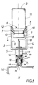
- FIG. 1 represents a schematic view, in longitudinal section, of a mode for producing the transfer device of the invention.
- Figure 2 shows a schematic view, in longitudinal section, of another embodiment of the transfer device of the invention.
- Figures 3, 4, 5 and 6 show schematic views, in section of the operation of the transfer device shown in the figure 2.
- the transfer device 1 comprises a first guide 2 capable of receiving, at least partially, a bottle 3.
- the first guide 2 is generally cylindrical in shape, the shape of the first guide depending on that of the bottle.
- the first guide can be of a shape other than cylindrical, for example parallelepiped, to adapt to bottles of a corresponding shape.
- the first guide 2 comprises a longitudinal wall 4 open to one of its ends 6 and closed at its opposite end 5.
- the first guide 2 is provided with means preventing the withdrawal of the bottle 3 from the first guide 2. These means also allow at least partial sliding of the bottle 3 in the first guide 2.
- the means preventing the removal include two elastic tabs 7 disposed on the inner face 8 of the longitudinal wall 4 of the first guide 2.
- the two tabs 7 are arranged so as to allow the introduction of the bottle 3 in the first guide 2 and to prevent its total withdrawal out of it while allowing said bottle 3 to slide in the first guide 2.
- the legs 7 deviate towards the face internal 8 of the first guide 2 under the action exerted by the neck 9 of the bottle 3.
- the neck 9 of the bottle 3 can then be introduced into the first guide 2.
- the legs 7 return to their initial position, the bottle 3 being partially introduced into the first guide 2, the neck 10 of the bottle 3 located at the legs 7.
- the legs 7 can then again move towards the internal face 8 of the first guide 2, to allow the sliding of said bottle so as to pass the body 11 of the bottle 3.
- the legs 7 are fixed to the internal face 8 of the first guide 2 by one of their ends 12, the other free end 13 of the legs 7 being directed towards the closed end of the first guide 2, so as to block the withdrawal of the bottle 3 outside the first guide 2, at the neck 10 of the bottle 3.
- the number of legs 7 may vary depending in particular on the resistance to withdrawal that one wishes to give to the transfer device 1 of the invention.
- the transfer device 1 comprises three legs 7 arranged substantially at the same level of the internal face 8 of the first guide 2 and spaced substantially evenly therebetween.
- the first guide 2 is extended on the side of the closed end 5 by a second guide 14.
- the second guide 14 is fixedly and coaxially arranged with respect to the median longitudinal axis X of the device 1, with the first guide 2.
- the second guide 14 is hollow and intended to receive the inlet orifice 15 of a solution bag 16.
- the inlet 15 includes an elastomer sleeve 28 passable by the needle 17 and self-concealing which is U-shaped and which is closed by a cover 23.
- the needle 17 passes through first the cover 23 to be in the airlock 29 formed inside the U then additional sliding brings the needle 17 into contact with the bottom 30 of the U so that it can pass through it and thus bring the interior of the solution bag with the outside.
- the second guide comprises means preventing total withdrawal of the inlet 15 outside the second guide 14 after its introduction into this one.
- the means preventing the total withdrawal have a structure identical to that of the means preventing the withdrawal of the bottle 3 and therefore comprise two elastic tabs 25 arranged on the internal face of the longitudinal wall of the second guide 14.
- the tabs 25 deviate towards the face internal of the second guide 14 under the action exerted. Blocking the withdrawal of the inlet 15 is then made between the free end 26 of the legs 25 and a circular flat 27 made on said orifice.
- the assembly formed by the pocket of solute 16 and the device 1 is then in a first position (see figure 2) in which although associated with one another, the needle 17 has not passed through the cover 23. Under the action of an additional force, the inlet 15 can then slide so that the needle is in the airlock 29 (second position shown in particular in Figure 1) then crosses the bottom 30 to put the inside of the solution bag 16 in contact with the inside of the bottle 3 (third position shown in particular in Figure 6).
- the second guide 14 comprises a hollow needle 17, substantially parallel to the median longitudinal axis X.
- the needle 17 is provided with two ends forming bevelled points 18, intended to pierce the inlet orifice 15 of the solute bag 16 on the one hand and the bottle cap 3 on the other hand.
- the needle 17 is held in place at the closed end 5 of the first guide 2, the two points 18 of the needle 17 opening for one in the first guide 2 and for the other in the second guide 14.
- the base region 19 makes it possible to prevent the needle 17 from becoming twists when piercing the bottle cap 3 or the inlet orifice 15 of the solution bag 16.
- the transfer device 1 can be made of an injectable plastic.
- the plastic used must also be able to withstand the conditions of sterilization.
- the transfer device can be made of a polymer based polyethylene, polycarbonate, polypropylene, polystyrene, as well as derivatives and / or mixtures of these products.
- the transfer device shown in Figure 1 is manufactured by injection, starting from the raw materials indicated above, the first and second guides being formed in one piece and the needle molded.
- FIG. 1 Another embodiment of the transfer device 1 is shown in the figure 2.
- the transfer device 1 comprises a first guide 2 and a second guide 14 into which open the points 18 of a needle 17.
- the second guide 14 is slidably mounted on the first guide 2.
- the second guide 14 comprises a region of smaller diameter external 20, located at the end of the second guide 14 located on the side of the first guide 2.
- This region of smaller external diameter 20 is slidably mounted in a corresponding opening made on the closed end 5 of the first guide 2.
- a more or less easy sliding of the second guide 14 can be obtained by depending on the choice of plastic materials used for the first and second guides and the external diameter of region 20 relative to the opening made on the closed end 5 of the first guide 2.
- Sliding can be further facilitated by depositing a silicone material on the region with the smallest external diameter 20.
- the sliding of the second guide 14 is limited in one direction by a lip annular 21 forming a bearing surface against the closed end 5 of the first guide 2, inside the first guide 2.
- the sliding of the second guide 14 is limited in the other direction by the return of the second guide 14 at its normal diameter, at region 22.
- the embodiment of the transfer device 1 according to the invention as illustrated in Figure 2 involves the separate manufacture of two corresponding parts to the first and second guides.
- FIGS 3, 4, 5 and 6 illustrate the operation of the transfer device according to the invention.
- FIGS. 3 to 6 the same reference numerals designate the same elements as in Figures 1 and 2.
- a transfer device 1 according to the invention is mounted, via the second guide 14, on the orifice inlet 15 of a solute bag 16 so as to make the device 1 integral and the solute bag 16.
- the other point 18 of the needle 17 located on the side of the first guide 2 is protected by a flexible self-sealing envelope 24, for example made of latex, for the purpose to guarantee the sterility of the transfer device 1.
- Such an envelope 24 can also be provided on the side of the point 18 of the needle 17 located on the side of the second guide 14.
- a bottle 3 containing for example a drug is introduced into the first guide 2 (figures 4 and 5).
- the bottle 3 is associated with the solute bag 16 by via the transfer device 1 to form a unitary assembly in which the interior of the bottle 3 and the interior of the pocket 16 are not communication.
- the solute bag 16, the device 1 and the bottle 3 are irreversibly associated with each other.
- unitary assembly is understood to mean in particular that it can be stored, sold, handled and used together.
- the stopper of the bottle 3 then comes into contact with the point 18 of the needle 17 protected by the casing 24.
- the operator can then exert a force on the solute bag 16 and on the bottle 3 so as to simultaneously cause on the one hand a sliding additional bottle 3 which leads to piercing the cap and the casing 24 by the needle 17 and on the other hand an additional sliding of the inlet orifice 15 which leads to the drilling of the bottom 30 by the other end 18 of needle 17.
- This action connects the interior of the bottle 3 with the interior of the solute bag 16, via the hollow needle 17 ( Figure 6).
- the solute bag 16 is positioned with the inlet port 15 facing the down to introduce, by exerting manual pressure on the solution bag 16, a small amount of solute inside the bottle 3 to dissolve the medicine it contains. After dissolution, the whole solution bag 16 and bottle 3 is inverted in order to transfer the contents of bottle 3 to the solution 16, the sterile air in the solution bag 16 replacing the contained liquid in bottle 3.
- the bottle 3 remains on the device 1 according to the invention, its withdrawal being prevented by the tabs 7 which block the passage of the neck 9 outside the first guide 2.
Abstract
Description
Claims (24)
- Dispositif (1) de transfert, dans une poche de soluté (16), d'une substance, par exemple médicamenteuse, contenue dans un récipient, tel qu'un flacon (3), comprenant :caractérisé en ce que le premier guide (2) est apte à recevoir non seulement le col (10) mais également la partie supérieure du corps (11) du flacon (3), et en ce que les moyens aptes à empêcher le retrait total du flacon (3) sont agencés de sorte à permettre le coulissement au moins partiel dudit flacon (3) dans le premier guide (2).un premier guide (2), de forme générale sensiblement cylindrique, ouvert à l'une de ses extrémités (6) et fermé à son autre extrémité (5) opposée à l'extrémité ouverte (6), ledit premier guide (2) comprenant des moyens aptes à empêcher le retrait total du flacon (3) hors du premier guide (2) après son introduction dans celui-ci;un second guide (14), de forme générale sensiblement cylindrique, prolongeant le premier guide (2) du côté de l'extrémité fermée (5) de celui-ci et monté de façon coaxiale avec le premier guide (2), l'extrémité du second guide (14) opposée au premier guide (2) étant ouverte et apte à recevoir l'orifice d'entrée (15) de la poche de soluté (16);un moyen de perçage des moyens de fermeture du flacon (3) et de la poche de soluté (16) respectivement, et de transfert de la substance contenue dans le flacon (3) dans la poche de soluté (16), les moyens de perçage étant disposés de façon coaxiale avec les premier (2) et second (14) guides ;
- Dispositif selon la revendication 1, caractérisé en ce que les moyens empêchant le retrait du flacon (3) comprennent au moins une patte élastique (7) ménagée sur la face interne (8) du premier guide (2), par exemple au niveau de l'extrémité ouverte (6) du premier guide (2), la patte (7) faisant saillie vers l'intérieur du premier guide (2) par l'une de ses extrémités (13) en étant dirigée vers l'extrémité fermée (5) du premier guide (2).
- Dispositif selon la revendication 2, caractérisé en ce que les pattes (7) sont fixées à la face interne (8) du premier guide (2) par l'une de leurs extrémités (12), l'autre extrémité (13) des pattes (7) étant dirigée vers l'extrémité fermée (5) du premier guide (2).
- Dispositif selon la revendication 2 ou 3, caractérisé en ce qu'il comporte trois pattes élastiques (7) disposées de façon sensiblement régulière entre elles et sensiblement au même niveau sur la face interne (8) du premier guide (2).
- Dispositif selon la revendication 1, caractérisé en ce que les moyens empêchant le retrait du flacon (3) comprennent au moins une lèvre annulaire élastique disposée sur la face interne (8) du premier guide (2), par exemple au niveau de l'extrémité ouverte (6) du premier guide (2), en faisant saillie vers l'intérieur du premier guide (2), de façon sensiblement perpendiculaire à l'axe longitudinal (X) du premier guide (2).
- Dispositif selon l'une quelconque des revendications 1 à 5, caractérisé en ce que le second guide (14) est fixé rigidement sur le premier guide (2).
- Dispositif selon l'une quelconque des revendications 1 à 5, caractérisé en ce que le second guide (14) est monté de façon coulissante sur le premier guide (2).
- Dispositif selon la revendication 7, caractérisé en ce que le second guide (14) comprend une région de plus petit diamètre externe (20), située vers l'extrémité du second guide (14) opposée à l'extrémité ouverte du second guide (14) et destinée à venir coulisser dans une ouverture de diamètre correspondant ménagée dans l'extrémité fermée (5) du premier guide (2).
- Dispositif selon la revendication 8, caractérisé en ce que la partie terminale de la région de plus petit diamètre (20) située du côté du premier guide (2) est munie d'une lèvre annulaire (21) formant une surface d'appui contre l'extrémité fermée (5) du premier guide (2), à l'intérieur de celui-ci, de façon à bloquer le coulissement du second guide (14) dans le premier guide (2).
- Dispositif selon la revendication 8 ou 9, caractérisé en ce que la région de plus petit diamètre (20) est revêtue d'une matière siliconée.
- Dispositif selon l'une quelconque des revendications 1 à 10, caractérisé en ce que les moyens de perçage des moyens de fermeture du flacon (3) et de l'orifice d'entrée (15) de la poche (16) comprennent une aiguille (17) creuse sur toute sa longueur, coaxiale avec les premier (2) et second (14) guides, les deux extrémités de l'aiguille (17) étant en forme de pointes (18) biseautées, en débouchant pour l'une dans le premier guide (2) et pour l'autre dans le second guide (14).
- Dispositif selon la revendication 11, caractérisé en ce que l'aiguille (17) est maintenue en place au niveau de l'extrémité fermée (5) du premier guide (2).
- Dispositif selon la revendication 12, caractérisé en ce qu'il comprend une région formant socle (19) du côté de l'extrémité fermée (5) du premier guide (2) ou, alternativement, du côté du second guide (14), pour renforcer la rigidité de l'aiguille (17).
- Dispositif selon la revendication 11, caractérisé en ce que l'aiguille (17) est maintenue en place au niveau de la région de plus faible diamètre (20) du second guide (14).
- Dispositif selon l'une quelconque des revendications 11 à 14, caractérisé en ce que la pointe (18) de l'aiguille (17) débouchant dans le premier guide (2) est protégée par une enveloppe souple (24), par exemple en latex.
- Dispositif selon l'une quelconque des revendications 11 à 15, caractérisé en ce que la pointe (18) de l'aiguille (17) débouchant dans le second guide (14) est protégée par une enveloppe souple auto rescellante (24), par exemple en latex.
- Dispositif selon l'une quelconque des revendications 1 à 16, caractérisé en ce qu'il est indépendant de la poche de soluté (16) et du flacon (3).
- Dispositif selon la revendication 17, caractérisé en ce que le second guide (14) comprend des moyens aptes à empêcher le retrait total de l'orifice d'entrée (15) de la poche de soluté (16) hors du second guide (14) après son introduction dans celui-ci.
- Dispositif selon la revendication 18, caractérisé en ce que les moyens empêchant le retrait de l'orifice d'entrée (15) ont une structure identique à celle des moyens empêchant le retrait du flacon (3) du premier guide (2) et sont agencés de sorte à permettre le coulissement au moins partiel dudit orifice d'entrée (15) dans le second guide (14).
- Dispositif selon l'une quelconque des revendications 1 à 16, caractérisé en ce qu'il est intégré de façon permanente et non détachable à la poche de soluté (16).
- Dispositif selon la revendication 20, caractérisé en ce qu'il est monté de façon fixe sur l'orifice d'entrée (15) de la poche de soluté (16), au niveau de l'extrémité ouverte du second guide (14).
- Dispositif selon la revendication 20 ou 21, caractérisé en ce qu'il est protégé de plus par un opercule reposant sur les parois longitudinales (4) du premier guide (2).
- Dispositif selon l'une quelconque des revendications 1 à 22, caractérisé en ce qu'il est réalisé en une matière plastique injectable et stérilisable.
- Dispositif selon la revendication 23, caractérisé en ce qu'il est réalisé à partir d'un polymère à base de polyéthylène, polycarbonate, polypropylène, polystyrène ainsi que les dérivés et/ou mélanges de ces produits.
Applications Claiming Priority (2)
| Application Number | Priority Date | Filing Date | Title |
|---|---|---|---|
| FR9902963 | 1999-03-10 | ||
| FR9902963A FR2790749B1 (fr) | 1999-03-10 | 1999-03-10 | Dispositif de transfert d'une substance contenue dans un flacon dans une poche de solute |
Publications (2)
| Publication Number | Publication Date |
|---|---|
| EP1034772A1 true EP1034772A1 (fr) | 2000-09-13 |
| EP1034772B1 EP1034772B1 (fr) | 2007-01-24 |
Family
ID=9543024
Family Applications (1)
| Application Number | Title | Priority Date | Filing Date |
|---|---|---|---|
| EP20000400612 Expired - Lifetime EP1034772B1 (fr) | 1999-03-10 | 2000-03-07 | Dispositif de transfert d'une substance contenue dans un flacon dans une poche de soluté |
Country Status (4)
| Country | Link |
|---|---|
| EP (1) | EP1034772B1 (fr) |
| AT (1) | ATE352274T1 (fr) |
| DE (1) | DE60033074D1 (fr) |
| FR (1) | FR2790749B1 (fr) |
Cited By (15)
| Publication number | Priority date | Publication date | Assignee | Title |
|---|---|---|---|---|
| FR2817465A1 (fr) * | 2000-12-06 | 2002-06-07 | Technoflex Sa | Dispositif de reconstitution notamment pour le melange de substances dans le domaine medical |
| FR2828803A1 (fr) * | 2001-08-22 | 2003-02-28 | Map France | Conditionnement de securite pour flacon a usage medical |
| WO2003066152A2 (fr) * | 2002-02-08 | 2003-08-14 | Alaris Medical Systems, Inc. | Adaptateur de flacon a soupape sans aiguille utilise pour des fermetures de flacon de differentes tailles |
| FR2863161A1 (fr) * | 2003-12-05 | 2005-06-10 | Map France | Capuchon pour conditionnement de securite pour flacon a usage medical |
| EP1917988A1 (fr) | 2006-10-31 | 2008-05-07 | Maco Pharma | Récipient équipé d'un système de transfert aseptique |
| WO2011124631A1 (fr) * | 2010-04-09 | 2011-10-13 | Sanofi-Aventis Deutschland Gmbh | Élément de raccordement de réservoir de médicament codé pourvu d'éléments de blocage pliables |
| WO2011124632A1 (fr) * | 2010-04-09 | 2011-10-13 | Sanofi-Aventis Deutschland Gmbh | Élément de raccordement à un réservoir de médicament codé pourvu d'un rebord articulé |
| US9180070B2 (en) | 2012-02-02 | 2015-11-10 | Becton Dickinson Holdings Pte. Ltd. | Adaptor for coupling to a medical container |
| USD747650S1 (en) | 2013-08-05 | 2016-01-19 | Becton Dickinson France | Blocking closure for container |
| US9549873B2 (en) | 2012-02-02 | 2017-01-24 | Becton Dickinson Holdings Pte. Ltd. | Adaptor for coupling to a medical container |
| US9668939B2 (en) | 2012-02-02 | 2017-06-06 | Becton Dickinson Holdings Pte. Ltd. | Adaptor for coupling with a medical container |
| US9713574B2 (en) | 2012-08-03 | 2017-07-25 | Becton Dickinson France | Dose counting device for coupling with a medical container |
| US10195112B2 (en) | 2012-11-26 | 2019-02-05 | Becton Dickinson France | Adaptor for multidose medical container |
| CN111474375A (zh) * | 2013-07-26 | 2020-07-31 | 积水医疗株式会社 | 试剂供给装置 |
| WO2024039713A1 (fr) * | 2022-08-16 | 2024-02-22 | Oyster Point Pharma, Inc. | Système de transfert de médicament configuré pour un transfert aseptique de produit liquide |
Families Citing this family (1)
| Publication number | Priority date | Publication date | Assignee | Title |
|---|---|---|---|---|
| FR2878737B1 (fr) | 2004-12-07 | 2007-03-16 | Maptech Soc Par Actions Simpli | Dispositif de securite pour flacon a usage medical |
Citations (5)
| Publication number | Priority date | Publication date | Assignee | Title |
|---|---|---|---|---|
| DE3016998A1 (de) * | 1979-05-02 | 1980-11-13 | Sigma Tau Ind Farmaceuti | Vorrichtung zum mischen und abgeben von zwei substanzen im sterilen zustand |
| WO1986001712A1 (fr) * | 1984-09-14 | 1986-03-27 | Baxter Travenol Laboratories, Inc. | Dispositif de reconstitution |
| WO1988001881A1 (fr) * | 1986-09-18 | 1988-03-24 | Aktiebolaget Leo | Raccord et unite jetable utilisant ledit raccord |
| FR2613220A1 (fr) * | 1987-04-06 | 1988-10-07 | Duphar Int Res | Ensemble a aiguille pour le transfert de liquides |
| FR2780878A1 (fr) * | 1998-07-10 | 2000-01-14 | Frederic Senaux | Capuchon de transfert encliquetable |
-
1999
- 1999-03-10 FR FR9902963A patent/FR2790749B1/fr not_active Expired - Fee Related
-
2000
- 2000-03-07 EP EP20000400612 patent/EP1034772B1/fr not_active Expired - Lifetime
- 2000-03-07 AT AT00400612T patent/ATE352274T1/de not_active IP Right Cessation
- 2000-03-07 DE DE60033074T patent/DE60033074D1/de not_active Expired - Lifetime
Patent Citations (5)
| Publication number | Priority date | Publication date | Assignee | Title |
|---|---|---|---|---|
| DE3016998A1 (de) * | 1979-05-02 | 1980-11-13 | Sigma Tau Ind Farmaceuti | Vorrichtung zum mischen und abgeben von zwei substanzen im sterilen zustand |
| WO1986001712A1 (fr) * | 1984-09-14 | 1986-03-27 | Baxter Travenol Laboratories, Inc. | Dispositif de reconstitution |
| WO1988001881A1 (fr) * | 1986-09-18 | 1988-03-24 | Aktiebolaget Leo | Raccord et unite jetable utilisant ledit raccord |
| FR2613220A1 (fr) * | 1987-04-06 | 1988-10-07 | Duphar Int Res | Ensemble a aiguille pour le transfert de liquides |
| FR2780878A1 (fr) * | 1998-07-10 | 2000-01-14 | Frederic Senaux | Capuchon de transfert encliquetable |
Cited By (37)
| Publication number | Priority date | Publication date | Assignee | Title |
|---|---|---|---|---|
| FR2817465A1 (fr) * | 2000-12-06 | 2002-06-07 | Technoflex Sa | Dispositif de reconstitution notamment pour le melange de substances dans le domaine medical |
| WO2002045649A1 (fr) * | 2000-12-06 | 2002-06-13 | Technoflex S.A. | Dispositif de reconstitution notamment pour le melange de substances dans le domaine medical |
| FR2828803A1 (fr) * | 2001-08-22 | 2003-02-28 | Map France | Conditionnement de securite pour flacon a usage medical |
| WO2003017916A1 (fr) * | 2001-08-22 | 2003-03-06 | M.A.P. France | Conditionnement de securite pour flacon a usage medical |
| US8177768B2 (en) | 2002-02-08 | 2012-05-15 | Carefusion 303, Inc. | Vial adapter having a needle-free valve for use with vial closures of different sizes |
| WO2003066152A2 (fr) * | 2002-02-08 | 2003-08-14 | Alaris Medical Systems, Inc. | Adaptateur de flacon a soupape sans aiguille utilise pour des fermetures de flacon de differentes tailles |
| US6875205B2 (en) | 2002-02-08 | 2005-04-05 | Alaris Medical Systems, Inc. | Vial adapter having a needle-free valve for use with vial closures of different sizes |
| CN1294889C (zh) * | 2002-02-08 | 2007-01-17 | 卡迪纳尔健康303公司 | 用于不同口径气口瓶的具有无针阀门的瓶转接器 |
| EP1797857A1 (fr) * | 2002-02-08 | 2007-06-20 | Cardinal Health 303, Inc. | Adaptateur pour flacon doté d'une vanne sans aiguille à utiliser avec des bouchons de flacon de différentes tailles |
| AU2003217342B2 (en) * | 2002-02-08 | 2009-06-18 | Carefusion 303, Inc. | Vial Adapter for Use with Vial Closures of Different Sizes |
| AU2003217342B8 (en) * | 2002-02-08 | 2009-07-23 | Carefusion 303, Inc. | Vial Adapter for Use with Vial Closures of Different Sizes |
| EP2255773A1 (fr) * | 2002-02-08 | 2010-12-01 | CareFusion 303, Inc. | Adaptateur pour flacon doté d'une vanne sans aiguille à utiliser avec des bouchons de flacon de différentes tailles |
| WO2003066152A3 (fr) * | 2002-02-08 | 2004-03-18 | Alaris Medical Syst Inc | Adaptateur de flacon a soupape sans aiguille utilise pour des fermetures de flacon de differentes tailles |
| FR2863161A1 (fr) * | 2003-12-05 | 2005-06-10 | Map France | Capuchon pour conditionnement de securite pour flacon a usage medical |
| WO2005055917A1 (fr) * | 2003-12-05 | 2005-06-23 | M.A.P. France | Capuchon pour conditionnement de securite pour flacon a usage medical |
| EP1917988A1 (fr) | 2006-10-31 | 2008-05-07 | Maco Pharma | Récipient équipé d'un système de transfert aseptique |
| US7621298B2 (en) | 2006-10-31 | 2009-11-24 | Maco Pharma, S.A. | Recipient equipped with an aseptic transfer system |
| JP2013523293A (ja) * | 2010-04-09 | 2013-06-17 | サノフィ−アベンティス・ドイチュラント・ゲゼルシャフト・ミット・ベシュレンクテル・ハフツング | ヒンジで動くフランジを備えたコード化薬物リザーバ連結エレメント |
| US9844630B2 (en) | 2010-04-09 | 2017-12-19 | Sanofi-Aventis Deutschland Gmbh | Coded drug reservoir connection element with hinged flange |
| CN102917740A (zh) * | 2010-04-09 | 2013-02-06 | 赛诺菲-安万特德国有限公司 | 具有铰接凸缘的编码药物贮存器连接元件 |
| JP2013523292A (ja) * | 2010-04-09 | 2013-06-17 | サノフィ−アベンティス・ドイチュラント・ゲゼルシャフト・ミット・ベシュレンクテル・ハフツング | 薬物リザーバの屈曲可能ロッキングエレメントを備えたコード化された連結エレメント |
| WO2011124631A1 (fr) * | 2010-04-09 | 2011-10-13 | Sanofi-Aventis Deutschland Gmbh | Élément de raccordement de réservoir de médicament codé pourvu d'éléments de blocage pliables |
| US20130253432A1 (en) * | 2010-04-09 | 2013-09-26 | Sanofi-Aventis Deutschland Gmbh | Coded drug reservoir connection element with hinged flange |
| US9061110B2 (en) | 2010-04-09 | 2015-06-23 | Sanofi-Aventis Deutschland Gmbh | Coded drug reservoir connection element with bendable locking elements |
| WO2011124632A1 (fr) * | 2010-04-09 | 2011-10-13 | Sanofi-Aventis Deutschland Gmbh | Élément de raccordement à un réservoir de médicament codé pourvu d'un rebord articulé |
| CN102917740B (zh) * | 2010-04-09 | 2017-02-08 | 赛诺菲-安万特德国有限公司 | 具有铰接凸缘的编码药物贮存器连接元件 |
| US9549873B2 (en) | 2012-02-02 | 2017-01-24 | Becton Dickinson Holdings Pte. Ltd. | Adaptor for coupling to a medical container |
| US9668939B2 (en) | 2012-02-02 | 2017-06-06 | Becton Dickinson Holdings Pte. Ltd. | Adaptor for coupling with a medical container |
| US9180070B2 (en) | 2012-02-02 | 2015-11-10 | Becton Dickinson Holdings Pte. Ltd. | Adaptor for coupling to a medical container |
| US10532005B2 (en) | 2012-02-02 | 2020-01-14 | Becton Dickinson Holdings Pte. Ltd. | Adaptor for coupling to a medical container |
| US10751252B2 (en) | 2012-02-02 | 2020-08-25 | Becton Dickinson Holdings Pte. Ltd. | Adaptor for coupling with a medical container |
| US10966903B2 (en) | 2012-02-02 | 2021-04-06 | Becton Dickinson Holdings Pte. Ltd. | Adaptor for coupling to a medical container |
| US9713574B2 (en) | 2012-08-03 | 2017-07-25 | Becton Dickinson France | Dose counting device for coupling with a medical container |
| US10195112B2 (en) | 2012-11-26 | 2019-02-05 | Becton Dickinson France | Adaptor for multidose medical container |
| CN111474375A (zh) * | 2013-07-26 | 2020-07-31 | 积水医疗株式会社 | 试剂供给装置 |
| USD747650S1 (en) | 2013-08-05 | 2016-01-19 | Becton Dickinson France | Blocking closure for container |
| WO2024039713A1 (fr) * | 2022-08-16 | 2024-02-22 | Oyster Point Pharma, Inc. | Système de transfert de médicament configuré pour un transfert aseptique de produit liquide |
Also Published As
| Publication number | Publication date |
|---|---|
| DE60033074D1 (de) | 2007-03-15 |
| FR2790749B1 (fr) | 2001-05-18 |
| ATE352274T1 (de) | 2007-02-15 |
| FR2790749A1 (fr) | 2000-09-15 |
| EP1034772B1 (fr) | 2007-01-24 |
Similar Documents
| Publication | Publication Date | Title |
|---|---|---|
| EP0403626B1 (fr) | Flacon de stockage et de transfert con u pour stocker deux composants d'une substance medicamenteuse | |
| EP0406374B1 (fr) | Flacon de stockage et de transfert con u pour stocker un composant d'une substance medicamenteuse | |
| EP1226077B1 (fr) | Dispositif de connexion pret a l'emploi | |
| EP0453555B1 (fr) | Flacon de stockage contenant un composant d'une solution medicamenteuse | |
| EP1827353B1 (fr) | Dispositif de securite pour flacon a usage medical | |
| EP1034772B1 (fr) | Dispositif de transfert d'une substance contenue dans un flacon dans une poche de soluté | |
| EP1079789B1 (fr) | Ampoule pour le conditionnement d'un liquide a usage medical | |
| FR2585577A1 (fr) | Dispositif pour connecter une extremite d'une canule de distribution d'un medicament liquide a un appareil pour relier une seringue a une fiole contenant le medicament | |
| FR2560049A1 (fr) | Dispositif de securite pour le raccordement d'une seringue avec l'ouverture d'une bouteille contenant un medicament ou d'un petit tube pour fourniture d'un medicament venant de la seringue | |
| EP1349530A1 (fr) | Ampoule pour le conditionnement et le transfert d'un liquide ou d'une poudre a usage medical | |
| WO1999036029A1 (fr) | Dispositif de confinement etanche, pour la connexion d'un recipient et d'un moyen de delivrance d'une matiere | |
| EP0732114A1 (fr) | Dispositif de perforation et ensemble de raccordement pour système d'alimentation par voie entérale et procédé de raccordement | |
| EP1949883B1 (fr) | Procédé et set de transfert d'un fluide entre deux récipients | |
| EP1345566B1 (fr) | Dispositif de reconstitution notamment pour le mélange de substances dans le domaine médical | |
| BE543440A (fr) | ||
| WO1998049994A1 (fr) | Dispositif de mise en solution d'un produit lyophilise, contenu dans une cartouche a usage unique utilisee dans un dispositif d'injection sans aiguille | |
| EP1435893B1 (fr) | Conditionnement de securite pour flacon a usage medical | |
| FR2665633A1 (fr) | Perfectionnements aux recipients a contenu sterile, notamment aux poches souples a usage medical. | |
| WO2011001125A1 (fr) | Ampoule à usage médical réalisée en matériau synthétique | |
| FR3128644A1 (fr) | Seringue préremplie (PFS) à tige de piston amovible, stockable le long du cylindre de seringue. | |
| FR2853830A1 (fr) | Capuchon de transfert a moyen d'etancheite |
Legal Events
| Date | Code | Title | Description |
|---|---|---|---|
| PUAI | Public reference made under article 153(3) epc to a published international application that has entered the european phase |
Free format text: ORIGINAL CODE: 0009012 |
|
| AK | Designated contracting states |
Kind code of ref document: A1 Designated state(s): AT BE CH CY DE DK ES FI FR GB GR IE IT LI LU MC NL PT SE |
|
| AX | Request for extension of the european patent |
Free format text: AL;LT;LV;MK;RO PAYMENT 20000320;SI |
|
| 17P | Request for examination filed |
Effective date: 20000920 |
|
| AKX | Designation fees paid |
Free format text: AT BE CH CY DE DK ES FI FR GB GR IE IT LI LU MC NL PT SE |
|
| AXX | Extension fees paid |
Free format text: RO PAYMENT 20000320 |
|
| 17Q | First examination report despatched |
Effective date: 20020314 |
|
| GRAP | Despatch of communication of intention to grant a patent |
Free format text: ORIGINAL CODE: EPIDOSNIGR1 |
|
| GRAS | Grant fee paid |
Free format text: ORIGINAL CODE: EPIDOSNIGR3 |
|
| GRAA | (expected) grant |
Free format text: ORIGINAL CODE: 0009210 |
|
| AK | Designated contracting states |
Kind code of ref document: B1 Designated state(s): AT BE CH CY DE DK ES FI FR GB GR IE IT LI LU MC NL PT SE |
|
| AX | Request for extension of the european patent |
Extension state: RO |
|
| PG25 | Lapsed in a contracting state [announced via postgrant information from national office to epo] |
Ref country code: NL Free format text: LAPSE BECAUSE OF FAILURE TO SUBMIT A TRANSLATION OF THE DESCRIPTION OR TO PAY THE FEE WITHIN THE PRESCRIBED TIME-LIMIT Effective date: 20070124 Ref country code: IE Free format text: LAPSE BECAUSE OF FAILURE TO SUBMIT A TRANSLATION OF THE DESCRIPTION OR TO PAY THE FEE WITHIN THE PRESCRIBED TIME-LIMIT Effective date: 20070124 Ref country code: AT Free format text: LAPSE BECAUSE OF FAILURE TO SUBMIT A TRANSLATION OF THE DESCRIPTION OR TO PAY THE FEE WITHIN THE PRESCRIBED TIME-LIMIT Effective date: 20070124 Ref country code: FI Free format text: LAPSE BECAUSE OF FAILURE TO SUBMIT A TRANSLATION OF THE DESCRIPTION OR TO PAY THE FEE WITHIN THE PRESCRIBED TIME-LIMIT Effective date: 20070124 Ref country code: DK Free format text: LAPSE BECAUSE OF FAILURE TO SUBMIT A TRANSLATION OF THE DESCRIPTION OR TO PAY THE FEE WITHIN THE PRESCRIBED TIME-LIMIT Effective date: 20070124 |
|
| REG | Reference to a national code |
Ref country code: GB Ref legal event code: FG4D Free format text: NOT ENGLISH |
|
| REG | Reference to a national code |
Ref country code: CH Ref legal event code: EP |
|
| REG | Reference to a national code |
Ref country code: IE Ref legal event code: FG4D Free format text: LANGUAGE OF EP DOCUMENT: FRENCH |
|
| REF | Corresponds to: |
Ref document number: 60033074 Country of ref document: DE Date of ref document: 20070315 Kind code of ref document: P |
|
| PG25 | Lapsed in a contracting state [announced via postgrant information from national office to epo] |
Ref country code: SE Free format text: LAPSE BECAUSE OF FAILURE TO SUBMIT A TRANSLATION OF THE DESCRIPTION OR TO PAY THE FEE WITHIN THE PRESCRIBED TIME-LIMIT Effective date: 20070424 |
|
| PG25 | Lapsed in a contracting state [announced via postgrant information from national office to epo] |
Ref country code: ES Free format text: LAPSE BECAUSE OF FAILURE TO SUBMIT A TRANSLATION OF THE DESCRIPTION OR TO PAY THE FEE WITHIN THE PRESCRIBED TIME-LIMIT Effective date: 20070505 |
|
| PG25 | Lapsed in a contracting state [announced via postgrant information from national office to epo] |
Ref country code: PT Free format text: LAPSE BECAUSE OF FAILURE TO SUBMIT A TRANSLATION OF THE DESCRIPTION OR TO PAY THE FEE WITHIN THE PRESCRIBED TIME-LIMIT Effective date: 20070625 |
|
| REG | Reference to a national code |
Ref country code: CH Ref legal event code: NV Representative=s name: ABREMA AGENCE BREVET ET MARQUES, GANGUILLET |
|
| NLV1 | Nl: lapsed or annulled due to failure to fulfill the requirements of art. 29p and 29m of the patents act | ||
| GBV | Gb: ep patent (uk) treated as always having been void in accordance with gb section 77(7)/1977 [no translation filed] |
Effective date: 20070124 |
|
| REG | Reference to a national code |
Ref country code: IE Ref legal event code: FD4D |
|
| PG25 | Lapsed in a contracting state [announced via postgrant information from national office to epo] |
Ref country code: GB Free format text: LAPSE BECAUSE OF FAILURE TO SUBMIT A TRANSLATION OF THE DESCRIPTION OR TO PAY THE FEE WITHIN THE PRESCRIBED TIME-LIMIT Effective date: 20070124 |
|
| PLBE | No opposition filed within time limit |
Free format text: ORIGINAL CODE: 0009261 |
|
| STAA | Information on the status of an ep patent application or granted ep patent |
Free format text: STATUS: NO OPPOSITION FILED WITHIN TIME LIMIT |
|
| 26N | No opposition filed |
Effective date: 20071025 |
|
| PG25 | Lapsed in a contracting state [announced via postgrant information from national office to epo] |
Ref country code: DE Free format text: LAPSE BECAUSE OF FAILURE TO SUBMIT A TRANSLATION OF THE DESCRIPTION OR TO PAY THE FEE WITHIN THE PRESCRIBED TIME-LIMIT Effective date: 20070425 Ref country code: MC Free format text: LAPSE BECAUSE OF NON-PAYMENT OF DUE FEES Effective date: 20070331 |
|
| PG25 | Lapsed in a contracting state [announced via postgrant information from national office to epo] |
Ref country code: IT Free format text: LAPSE BECAUSE OF FAILURE TO SUBMIT A TRANSLATION OF THE DESCRIPTION OR TO PAY THE FEE WITHIN THE PRESCRIBED TIME-LIMIT Effective date: 20070124 Ref country code: GR Free format text: LAPSE BECAUSE OF FAILURE TO SUBMIT A TRANSLATION OF THE DESCRIPTION OR TO PAY THE FEE WITHIN THE PRESCRIBED TIME-LIMIT Effective date: 20070425 |
|
| PGFP | Annual fee paid to national office [announced via postgrant information from national office to epo] |
Ref country code: CH Payment date: 20090331 Year of fee payment: 10 |
|
| PG25 | Lapsed in a contracting state [announced via postgrant information from national office to epo] |
Ref country code: CY Free format text: LAPSE BECAUSE OF FAILURE TO SUBMIT A TRANSLATION OF THE DESCRIPTION OR TO PAY THE FEE WITHIN THE PRESCRIBED TIME-LIMIT Effective date: 20070124 |
|
| PGFP | Annual fee paid to national office [announced via postgrant information from national office to epo] |
Ref country code: BE Payment date: 20090326 Year of fee payment: 10 |
|
| PG25 | Lapsed in a contracting state [announced via postgrant information from national office to epo] |
Ref country code: LU Free format text: LAPSE BECAUSE OF NON-PAYMENT OF DUE FEES Effective date: 20070307 |
|
| PGFP | Annual fee paid to national office [announced via postgrant information from national office to epo] |
Ref country code: FR Payment date: 20090325 Year of fee payment: 10 |
|
| BERE | Be: lapsed |
Owner name: MACO PHARMA Effective date: 20100331 |
|
| REG | Reference to a national code |
Ref country code: CH Ref legal event code: PL |
|
| REG | Reference to a national code |
Ref country code: FR Ref legal event code: ST Effective date: 20101130 |
|
| PG25 | Lapsed in a contracting state [announced via postgrant information from national office to epo] |
Ref country code: FR Free format text: LAPSE BECAUSE OF NON-PAYMENT OF DUE FEES Effective date: 20100331 |
|
| PG25 | Lapsed in a contracting state [announced via postgrant information from national office to epo] |
Ref country code: LI Free format text: LAPSE BECAUSE OF NON-PAYMENT OF DUE FEES Effective date: 20100331 Ref country code: BE Free format text: LAPSE BECAUSE OF NON-PAYMENT OF DUE FEES Effective date: 20100331 Ref country code: CH Free format text: LAPSE BECAUSE OF NON-PAYMENT OF DUE FEES Effective date: 20100331 |