EP1034696A1 - Schleifvorrichtung - Google Patents
Schleifvorrichtung Download PDFInfo
- Publication number
- EP1034696A1 EP1034696A1 EP00104617A EP00104617A EP1034696A1 EP 1034696 A1 EP1034696 A1 EP 1034696A1 EP 00104617 A EP00104617 A EP 00104617A EP 00104617 A EP00104617 A EP 00104617A EP 1034696 A1 EP1034696 A1 EP 1034696A1
- Authority
- EP
- European Patent Office
- Prior art keywords
- grindstone
- holder
- grinding device
- grinding
- end position
- Prior art date
- Legal status (The legal status is an assumption and is not a legal conclusion. Google has not performed a legal analysis and makes no representation as to the accuracy of the status listed.)
- Granted
Links
- 239000004575 stone Substances 0.000 claims abstract description 27
- 238000006073 displacement reaction Methods 0.000 claims abstract description 9
- 239000004459 forage Substances 0.000 claims description 3
- 230000004913 activation Effects 0.000 claims description 2
- 238000001514 detection method Methods 0.000 claims description 2
- 238000005553 drilling Methods 0.000 claims 1
- 238000003306 harvesting Methods 0.000 description 6
- 238000000034 method Methods 0.000 description 6
- 230000008569 process Effects 0.000 description 6
- ORQBXQOJMQIAOY-UHFFFAOYSA-N nobelium Chemical compound [No] ORQBXQOJMQIAOY-UHFFFAOYSA-N 0.000 description 5
- 210000003746 feather Anatomy 0.000 description 2
- 239000000463 material Substances 0.000 description 2
- 244000025254 Cannabis sativa Species 0.000 description 1
- 241001124569 Lycaenidae Species 0.000 description 1
- 244000046127 Sorghum vulgare var. technicum Species 0.000 description 1
- 230000009286 beneficial effect Effects 0.000 description 1
- 230000008859 change Effects 0.000 description 1
- 238000006243 chemical reaction Methods 0.000 description 1
- 238000010276 construction Methods 0.000 description 1
- 238000005516 engineering process Methods 0.000 description 1
- 239000003292 glue Substances 0.000 description 1
- 239000004519 grease Substances 0.000 description 1
- 230000003993 interaction Effects 0.000 description 1
- 230000001050 lubricating effect Effects 0.000 description 1
- 238000004519 manufacturing process Methods 0.000 description 1
- 230000007246 mechanism Effects 0.000 description 1
- 210000002445 nipple Anatomy 0.000 description 1
- 230000009467 reduction Effects 0.000 description 1
- 230000000284 resting effect Effects 0.000 description 1
- 230000000630 rising effect Effects 0.000 description 1
Images




Classifications
-
- A—HUMAN NECESSITIES
- A01—AGRICULTURE; FORESTRY; ANIMAL HUSBANDRY; HUNTING; TRAPPING; FISHING
- A01F—PROCESSING OF HARVESTED PRODUCE; HAY OR STRAW PRESSES; DEVICES FOR STORING AGRICULTURAL OR HORTICULTURAL PRODUCE
- A01F29/00—Cutting apparatus specially adapted for cutting hay, straw or the like
- A01F29/09—Details
- A01F29/22—Arrangement of knife sharpening devices
-
- B—PERFORMING OPERATIONS; TRANSPORTING
- B24—GRINDING; POLISHING
- B24B—MACHINES, DEVICES, OR PROCESSES FOR GRINDING OR POLISHING; DRESSING OR CONDITIONING OF ABRADING SURFACES; FEEDING OF GRINDING, POLISHING, OR LAPPING AGENTS
- B24B3/00—Sharpening cutting edges, e.g. of tools; Accessories therefor, e.g. for holding the tools
- B24B3/36—Sharpening cutting edges, e.g. of tools; Accessories therefor, e.g. for holding the tools of cutting blades
- B24B3/368—Sharpening cutting edges, e.g. of tools; Accessories therefor, e.g. for holding the tools of cutting blades installed as an accessory on another machine
-
- B—PERFORMING OPERATIONS; TRANSPORTING
- B24—GRINDING; POLISHING
- B24B—MACHINES, DEVICES, OR PROCESSES FOR GRINDING OR POLISHING; DRESSING OR CONDITIONING OF ABRADING SURFACES; FEEDING OF GRINDING, POLISHING, OR LAPPING AGENTS
- B24B49/00—Measuring or gauging equipment for controlling the feed movement of the grinding tool or work; Arrangements of indicating or measuring equipment, e.g. for indicating the start of the grinding operation
- B24B49/18—Measuring or gauging equipment for controlling the feed movement of the grinding tool or work; Arrangements of indicating or measuring equipment, e.g. for indicating the start of the grinding operation taking regard of the presence of dressing tools
- B24B49/183—Wear compensation without the presence of dressing tools
Definitions
- the invention relates to a grinding device with a Whetstone on one in a first direction slidably mounted grindstone holder and by means of an infeed device relative to the grindstone holder in a second, from the first direction different direction is movable to the grindstone to deliver a knife.
- the key idea is to make the grindstone relative to the Grinding stone holder only slidable, and not to be rotatably supported. In this way, the grindstone at Delivery only postponed, but not relative to the grindstone holder rotated around its axis. Because of the missing Rotation has the entire effective area of the grindstone constant contact with the grinding surface of the knives. The beneficial The result is a reduced one with little design effort Wear of the grindstone, faster grinding, one better grinding quality and a reduction in through uneven surface of the grindstone in the state of the Technology resulting vibrations.
- the delivery device comprises a cam or Gear wheel that is at one end position (or both end positions) the displacement of the grindstone holder by one certain angle is rotated.
- the cam or gear can in this case be fixed to a second element, the is rotatably mounted relative to the grindstone holder.
- the Rotation of the cam or gear is preferably done by a corresponding jack, which is stationary near the End point of the displacement of the grindstone holder is attached, for example to a housing or frame Grinding device.
- the grindstone on a first element is attached, which is relative to the grindstone holder positive and / or non-positive against rotation secured but slidably mounted.
- the feather key allows the first element relative to the grindstone holder, but none Rotation.
- this can be done with the grindstone connected first element a different from the circular shape Have outside and / or inside cross section.
- the anti-rotation lock if the first Element with the non-cylindrical area, in particular can be flat, slidable on the grindstone holder is present. It would also be conceivable that the first element is not direct on the grindstone holder, but on one with it connected element is present. While a positive Locking for manufacturing reasons more complex than is a non-positive locking, it will be suitable also to absorb higher torques, as with the side Moving the grindstone from one row of knives to neighboring knife row occur. It can also be a form fit combined with a non-positive locking become.
- a flat section can be used for positive locking of the first element between a wall of the grindstone holder and one connected to the grindstone holder
- Anti-rotation plate can be arranged, or alternatively or additionally positioned between ridges of the grindstone holder become. This ensures adequate security against Rotation.
- the delivery device is turned on and off can be turned off by using the grindstone holder moved into different end positions.
- a first The end position is actuated and the Move the grindstone closer to the knife to be sharpened, and in a second end position there is no delivery.
- the grindstone holder in the second end position while in the normal Grinding is moved to the first end position, in which a The grinding stone is delivered.
- a simple way and at unproblematic mechanical feasibility through suitable Control of a driving the grindstone holder (Electric) motor is an optimal grinding with subsequent finishing carried out.
- the above different end positions of the grindstone holder can be on only one side of the knife, or on both sides of the Knives can be realized.
- the control of the displacement path can, for example, via the Number of activation pulses applied to the motor (in particular with a stepper motor) or a period of time during an operating voltage is applied to the motor or a Detection of the position of the grindstone holder or one of the Motor translatory and / or rotationally driven shaft and appropriate control of the engine. So it's easy controllable whether the grinding stone is delivered - or Not. It should be noted that the grindstone holder after To reach the end position in the opposite direction is what is done by reversing the direction of movement of the Engine can be done; for example, would be a DC motor just to change the polarity.
- the delivery device of the grindstone holder works in the first end position with a device to actuate the delivery device together, in particular a pawl turning a gear.
- the second end position is then chosen such that no interaction between the Device for actuating the delivery device and the Delivery device occurs so that the delivery is omitted.
- the present invention is in a variety of Devices with knives to be sharpened can be used. she can especially on self-propelled or trailed harvesters can be used with chopping drums.
- a harvesting machine 10 shown in FIG. 1 in the manner of a self-propelled forage harvester is built on a frame 12 on carried by front and rear wheels 14 and 16 becomes.
- the harvesting machine 10 is operated by a Driver's cab 18, from which a crop receiving device 20 is visible.
- goods picked up from the ground e.g. B. corn, grass or the like is fed to a chopper drum 22, which it in small Chops pieces and gives it to a conveyor 24.
- the Well the harvesting machine 10 leaves for a vehicle traveling alongside Trailer over a rotating discharge chute 26.
- No further details of the harvesting machine 10 are required Description because it is known per se.
- the location of the Post-shredding device 28, however, is not critical so that they are also downstream of the conveyor device 24 can be provided.
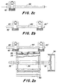
- FIG 2a is a schematic view of a chopper drum 22 and a grinding device assigned to it, as seen when viewing the harvester 10 in Figure 1 (with respect to the direction of movement) results from the front.
- the Chopper drum 22 has a number across their width and their Scope of distributed knife 38 in cooperation with a rigid shear bar 46 through the crop receiving device Cut up 20 harvested crops.
- the Chopper drum 22 includes a central shaft 32 which has a Face of the pulley 36 and belt, not shown can be driven in rotation by a motor of the harvesting machine 10.
- the shaft 34 is supported by two on both sides of the Chopping drum 22 arranged bearings on the frame 12 of the Harvester 10 off.
- the distance from the shear bar 46 is one hand the distance from the shear bar 46, on the other hand the sharpness the knife 38 critical. Is the distance from the shear bar 46 too low, the knives 38 can be damaged, it is too large, the harvested crop cannot be crushed properly become.
- the present invention relates to second mentioned problem, the sharpness of the knife 38. To after sharpen the blades 38 for a certain operating time can without the individual knife 38 or the entire The need to remove the chopper drum 22 is above the Chopper drum 22 close to that described by knives 38 Envelope a grinding device provided in essentially a grindstone 42, one associated with it Grinding stone holder 40 and an axis 44 on which the Whetstone holder 40 is slidably mounted.
- Figures 2a to 2c serve to illustrate the Operation of the grinding device.
- the chopper drum 22 rotates offset, usually in the opposite direction of rotation and / or with reduced speed compared to normal chopping.
- the grindstone holder 40 with the attached Grinding stone 42 is from a resting or shown in Figure 2c Parking position, in the side next to the chopper drum 22 is arranged over the entire width of the chopper drum 22 moved.
- the bottom of the grindstone is 22 in Contact with the knives 38, and sharpen them.
- a grinding process runs in such a way that the grindstone 42 several times over the Width of the chopper drum 22 is moved.
- FIG 3 is a partially sectioned view of the Whetstone holder 40 transverse to their direction of movement reproduced.
- the grindstone holder 40 is based on one on the axis 44, the other on a rail 54, the with a housing or frame 50 of the grinding device connected is.
- the rail 54 is approximately vertical connected between the grindstone holder 40 Ball bearings 52 and one also with the grindstone holder 40 connected counter-holder plate 56 arranged.
- the grindstone holder 40 against the Axis 44 and the ball bearing 52 presses against the rail 54.
- the counter plate 56 is over several (for example two) screws 58, only one of which is connected to the grindstone holder 40, and essentially serves to tilt the Grindstone holder 40 counter-clockwise about axis 44 to prevent when no grinding is being carried out will, e.g. B. in the parking position.
- a cable pull device 60 is provided, which is known per se is and therefore requires no further explanation. It would be alternatively also conceivable, the grindstone holder 40 over a revolving chain driven by a motor move.
- an infeed device 62 is shown in FIG shown, which has a gear 64. The function of the Delivery device 62, the grindstone 42 in the figure 2a with the reference numeral 40 ' Chopping drum 22 is delivered, is based on FIGS. 4 to 8 explained.
- FIG 4 is a view of the grinding device from above reproduced. It is indicated schematically that the Grindstone holder 40 between the one shown below Parking position and the one shown above (right in Figure 2a) Reverse position in which the second grindstone holder shown is identified by the reference symbol 40 ', is movable.
- the cable device 60 with a rope and an electrically driven linear motor 70 is also reproduced.
- other components of the Delivery device 62 at the reversed position shown above the grindstone holder 40 is provided.
- the feed device 62 comprises a pawl 68 on the frame 50 about an axis of rotation 72 which is perpendicular to the Drawing plane runs, is pivotally attached and through a Spring 66 is held in a rest position.
- the jack is 68 attached such that they against the gear 64 of the Whetstone holder 40 'bumps when the latter of their (in Figure 4 drawn above) reversing position, and that Gear 64 'rotates clockwise by one tooth.
- Jack 68 and gear 64 are shaped so that the tip of the pawl 68 first in the valley between two teeth of the gear 64 engages, and after a certain angle of rotation from outside rising flank of the following tooth against the Force of the spring 66 is pressed outwards.
- the flanks of the The teeth of the gear 64 are sawtooth-shaped asymmetrical designed to engage and disengage the pawl 68 facilitate.
- the angle of rotation of the gear 64 is 360 ° divided by the number of teeth, which is twelve in Figure 4; so the gear 64 turns clockwise by 30 ° turned. As a result, the gear 64 becomes one tooth at a time rotated clockwise when the grindstone holder 40 reached its reversal position (shown in Figure 4 above).
- the gear 64 is rotated by a suitable mechanism implemented in a feed movement of the grindstone 42 what is explained with reference to the following figures. If the Whetstone holder 40 is not fully in the reverse position is moved, but the shifting movement shortly before is interrupted, as indicated in Figure 2b, the pawl comes 68 not in contact with the gear 64, and the delivery of the Grinding stone 42 is omitted, as required for finishing.
- the gear 64 can against other gears with different Interchangeable number of teeth to the angle of rotation and thus the Delivery route, for example, to adapt to the material of the Grinding stone 42 and the knife 38 can vary.
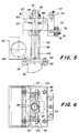
- FIGS. 5 and 6 a grindstone holder 40 is shown in FIG a first embodiment of the invention in a partially cut Rendered view.
- the grindstone 42 is on the bottom of the grindstone holder 40 at a first Plate 80 usually fixed by glue.
- the first Plate 80 is pierced at its four corners, and through which Holes 78 extend through first plate 80 is releasably attached to a second plate 84.
- the second plate 84 is connected to a block-shaped first element 82 which extends vertically and with a Internal thread is provided.
- the first element 82 is relative to the Grinding stone holder 40 slidable in the vertical direction stored, and positively against rotation relative to Grindstone holder 40 secured.
- Rotary lock plates are used for this 100 and webs 101, which can be seen in Figure 6 are and will be explained with reference to this figure.
- grindstone 42 serves an elongated second Element 86 with external thread that fits into the internal thread of the first Elements 82 is screwed into it. Act on both threads it is left-hand thread; intended to use right hand threads find, the direction of rotation of the gear 64 is to reverse what by turning the gear 64 and repositioning the pawl 68 can be done.
- the second element 86 rotates the first element 82 becomes vertical by the thread Direction shifted.
- the second element 86 is through ball bearings 88 rotatable relative to the grindstone holder 40, but not slidably mounted, and on its, the first element 82nd opposite upper part 92 rigid (and thus torque-locking) connected to the gear 64. They serve top and washers 90 arranged below the gear 64, a nut 94 and one secured with a split pin Crown nut 96, which the gear 64 rigidly with the upper part 92nd of the second element 86 connect. The result turns to Rotation of the gear 64, the entire second element 86 so that the external thread of the second element 86 relative to the Internal thread of the first element 80 rotates and the latter in vertically shifted, but due to its in Figure 6 rotation lock shown is not rotated. In Figure 5 is continue the attachment of the counter plate 56 on the Whetstone holder 40 with a screw 58, and the Fixation of the ball bearing 52 on the grindstone holder a screw 74 and washers 76 can be seen.
- the cross section of the hatched first element 82 recognizable, that with a (shown on the left) surface on a flat wall the grindstone holder 40 rests.
- the first element 82 has three step-shaped sections of different distances from said wall of the grindstone holder 40, from which the middle one receives the second element 86, and therefore spaced further from the wall while the two outer ones (upper and lower) sections are flatter, i.e. closer to the Wall lying.
- the first element 82 thus has a cross section that corresponds to a lying T.
- first element 82 On the outside Portions of the first element 82 lie above Anti-rotation plates 100 on, which by screws 98 with the Grinding stone holder 40 are connected.
- the first element 82 is thus in the grindstone holder 40 in the Drawing plane of Figure 6 vertical direction stored and by the anti-rotation plates 100 in (with respect 6) secured against rotation in the horizontal direction.
- the ball bearings 88 are used for guidance and by webs 101 of the grindstone holder 40 above and below the first element 82 into which the screws 98 engage with which the rotation lock plates 100 are attached are.
- Through grease nipples in the first element 82 and Whetstone holder 40 can ease the Thread rotation and displacement of the first element 82 get supported.
- FIGS Whetstone holder 40 '' reproduced.
- the whetstone 42 is attached to a first plate 80 which is fastened by screws 78 and nuts are fixed to a second plate 84.
- the second element 86 and its attachment to the grindstone holder 40 '' via ball bearings 88 and the attachment to Gear 64 is identical to the second shown in Figure 5 Element 86 according to the first embodiment of the invention.
- the Grinding stone holder 40 ′′ according to the second embodiment differs from the first embodiment in terms of locking the first element 102 (and the grindstone 42) against rotation: in the outer circumference of the cylindrical first Element 102 and / or in the inner circumference of the first element 102 surrounding area of the grindstone holder 40 can two diametrically opposite parallel key mounts 104 be introduced, i.e. 7 in the vertical direction extending grooves into which a key (not shown) is inserted.
- the feather key allows the first to be moved Elements 102 relative to grindstone holder 40 '' in vertical direction (with reference to Figure 8), but no rotation about the axis of the first element 102.
- Embodiment can provide means for lubricating the first Elements 102 in its plain bearing and the thread be provided.
- the first element shifts 102 with the grindstone 42 when the gear 64 rotates down, but does not turn around its axis.
Landscapes
- Engineering & Computer Science (AREA)
- Mechanical Engineering (AREA)
- Life Sciences & Earth Sciences (AREA)
- Environmental Sciences (AREA)
- Finish Polishing, Edge Sharpening, And Grinding By Specific Grinding Devices (AREA)
Abstract
Description
- Fig. 1
- eine Erntemaschine mit einer Häckseltrommel mit Schleifvorrichtung in Seitenansicht und in schematischer Darstellung,
- Fig. 2a
- eine Frontansicht einer Schleifvorrichtung in den während des Schleifens eingenommenen Endpositionen,
- Fig. 2b
- die Schleifvorrichtung in den Positionen beim Schlichten,
- Fig. 2c
- die Schleifvorrichtung in Ruheposition,
- Fig. 3
- eine teilgeschnittene vertikale Seitenansicht einer Schleifvorrichtung quer zu ihrer Bewegungsrichtung,
- Fig. 4
- eine Draufsicht auf die Schleifvorrichtung,
- Fig. 5
- eine teilgeschnittene vertikale Ansicht einer ersten Ausführungsform einer Schleifsteinhalterung,
- Fig. 6
- eine Draufsicht auf die Schleifsteinhalterung in Figur 5,
- Figur 7
- eine teilgeschnittene vertikale Ansicht einer zweiten Ausführungsform einer Schleifsteinhalterung, und
- Figur 8
- eine Draufsicht auf die Schleifsteinhalterung der Figur 7.
Claims (17)
- Schleifvorrichtung, mit einem Schleifstein (42), der an einer in einer ersten Richtung verschiebbar gelagerten Schleifsteinhalterung (40) gehalten und mittels einer Zustelleinrichtung (62) relativ zur Schleifsteinhalterung (40) in einer zweiten, von der ersten Richtung unterschiedlichen Richtung bewegbar ist, um den Schleifstein (42) einem Messer (38) zuzustellen, dadurch gekennzeichnet, daß der Schleifstein (42) durch die Zustelleinrichtung (62) ausschließlich verschoben wird.
- Schleifvorrichtung nach Anspruch 1, dadurch gekennzeichnet, daß der Schleifstein (42) an einem ersten Element (82,102) mit einem ersten Gewinde befestigt ist, das mit einem mit der Zustelleinrichtung (62) zusammenarbeitenden zweiten Gewinde zusammenwirkt, das beim Zustellen in Rotation versetzt wird.
- Schleifvorrichtung nach einem Ansprüche 1 oder 2, dadurch gekennzeichnet, daß die Zustelleinrichtung (62) ein Nocken- oder Zahnrad (64) umfaßt, das an wenigstens einer Endstellung des Verschiebeweges der Schleifsteinhalterung (40) insbesondere durch eine Klinke (68) gedreht wird.
- Schleifvorrichtung nach Anspruch 3, dadurch gekennzeichnet, daß das Nocken- oder Zahnrad (64) an einem zweiten Element (86) befestigt ist, das relativ zur Schleifsteinhalterung (40) drehbar gelagert ist.
- Schleifvorrichtung nach einem der vorhergehenden Ansprüche, dadurch gekennzeichnet, daß der Schleifstein (42) an einem ersten Element (82,102) befestigt ist, das relativ zur Schleifsteinhalterung (40) form- und/oder kraftschlüssig gegen Rotation gesichert, aber verschiebbar ist.
- Schleifvorrichtung nach Anspruch 5, dadurch gekennzeichnet, daß das erste Element (102) durch eine Paßfeder gegen Rotation gesichert ist.
- Schleifvorrichtung nach Anspruch 6, dadurch gekennzeichnet, daß die Paßfeder zwischen dem Außenumfang des ersten Elements (102) und einer es umschließenden Öffnung, insbesondere Bohrung, der Schleifsteinhalterung (40) in einer Paßfederaufnahme (104) angeordnet ist.
- Schleifvorrichtung nach einem der Ansprüche 5 bis 7, dadurch gekennzeichnet, daß das erste Element (82) einen von der Kreisform abweichenden Außen- und/oder Innenquerschnitt aufweist, mit dem das erste Element (82) an der Schleifsteinhalterung (40) verschiebbar anliegt.
- Schleifvorrichtung nach Anspruch 8, dadurch gekennzeichnet, daß ein Teilbereich des ersten Elements (82) flach ist.
- Schleifvorrichtung nach Anspruch 9, dadurch gekennzeichnet, daß der flache Teilbereich des ersten Elements (82) zwischen einer Wand der Schleifsteinhalterung (40) und einer mit der Schleifsteinhalterung (40) verbundenen Drehsicherungsplatte (100) angeordnet ist.
- Schleifvorrichtung nach Anspruch 9 oder 10, dadurch gekennzeichnet, daß das erste Element (82) zwischen Stegen (101) der Schleifsteinhalterung (44) angeordnet ist.
- Schleifvorrichtung nach einem der vorhergehenden Ansprüche, dadurch gekennzeichnet, daß die Zustelleinrichtung (62) durch Steuerung der Endstellung des Verschiebeweges der Schleifsteinhalterung (40) ein- und ausschaltbar ist.
- Schleifvorrichtung nach Anspruch 12, dadurch gekennzeichnet, daß die Schleifsteinhalterung (40) in eine erste Endstellung (40') und eine zweite Endstellung (40'') verschiebbar ist, und die Zustelleinrichtung (62) in der ersten Endstellung (40') aktiviert wird, aber in der zweiten Endstellung (40'') nicht aktiviert wird.
- Schleifvorrichtung nach Anspruch 12 oder 13, dadurch gekennzeichnet, daß die Schleifsteinhalterung (40) in der ersten Endstellung (40'), jedoch nicht in der zweiten Endstellung (40''), mit einer Vorrichtung zur Betätigung der Zustelleinrichtung (62) wechselwirkt.
- Schleifvorrichtung nach einem der Ansprüche 12 bis 14, dadurch gekennzeichnet, daß die Steuerung des Verschiebeweges über die Anzahl an einen Elektromotor (70) angelegter Aktivierungsimpulse und/oder eine Zeitdauer, während der eine Betriebsspannung an den Motor (70) angelegt wird und/oder eine Detektion der Position der Schleifsteinhalterung und/oder einer vom Motor (70) rotativ und/oder translatorisch angetriebenen Welle und entsprechende Steuerung des Motors (70) erfolgt.
- Schleifvorrichtung nach einem der vorhergehenden Ansprüche, dadurch gekennzeichnet, daß der Schleifstein (42) in vertikaler Richtung zugestellt wird.
- Erntemaschine, insbesondere selbstfahrender oder gezogener Feldhäcksler, mit einer Häckseltrommel (22) und einer Schleifvorrichtung nach einem der Ansprüche 1 bis 16.
Applications Claiming Priority (2)
| Application Number | Priority Date | Filing Date | Title |
|---|---|---|---|
| DE19910757A DE19910757A1 (de) | 1999-03-11 | 1999-03-11 | Schleifvorrichtung |
| DE19910757 | 1999-03-11 |
Publications (2)
| Publication Number | Publication Date |
|---|---|
| EP1034696A1 true EP1034696A1 (de) | 2000-09-13 |
| EP1034696B1 EP1034696B1 (de) | 2002-06-26 |
Family
ID=7900533
Family Applications (1)
| Application Number | Title | Priority Date | Filing Date |
|---|---|---|---|
| EP00104617A Expired - Lifetime EP1034696B1 (de) | 1999-03-11 | 2000-03-03 | Schleifvorrichtung |
Country Status (4)
| Country | Link |
|---|---|
| US (1) | US6450866B1 (de) |
| EP (1) | EP1034696B1 (de) |
| CA (1) | CA2300611C (de) |
| DE (2) | DE19910757A1 (de) |
Cited By (3)
| Publication number | Priority date | Publication date | Assignee | Title |
|---|---|---|---|---|
| BE1023897B1 (de) * | 2016-02-02 | 2017-09-07 | Claas Saulgau Gmbh | Schleifvorrichtung für Häckselmesser eines Häckselwerks und Häckselwerk |
| EP3925429A1 (de) * | 2020-06-17 | 2021-12-22 | CLAAS Selbstfahrende Erntemaschinen GmbH | Feldhäcksler |
| DE102014221465B4 (de) | 2014-10-22 | 2023-03-16 | Deere & Company | Schleifeinrichtung |
Families Citing this family (10)
| Publication number | Priority date | Publication date | Assignee | Title |
|---|---|---|---|---|
| DE10346116A1 (de) | 2003-10-04 | 2005-04-21 | Deere & Co | Häckseleinrichtung für einen Feldhäcksler |
| DE102012201334B4 (de) | 2012-01-31 | 2023-03-16 | Deere & Company | Feldhäcksler mit Häckselanordnung |
| DE102013101183A1 (de) * | 2013-02-07 | 2014-08-07 | Claas Selbstfahrende Erntemaschinen Gmbh | Landwirtschaftliche Arbeitsmaschine, insbesondere Feldhäcksler |
| DE102013211829B4 (de) * | 2013-06-21 | 2023-03-16 | Deere & Company | Element zum Abstützen und/oder Leiten von Erntegut in einer Erntemaschine |
| GB201420220D0 (en) * | 2014-11-13 | 2014-12-31 | Agco Int Gmbh | Knife sharpening apparatus for an agricultural machine |
| CN110026834A (zh) * | 2019-04-08 | 2019-07-19 | 四川省青城机械有限公司 | 一种成型刀在线磨刀装置 |
| DE102020126099A1 (de) | 2020-10-06 | 2022-04-07 | Deere & Company | Schleifeinrichtung für eine mit einer Anzahl an Messern versehene Häckseltrommel eines Feldhäckslers |
| DE102020128518A1 (de) | 2020-10-29 | 2022-05-05 | Deere & Company | Steueranordnung für eine Schleifeinrichtung und eine Einrichtung zur Verstellung der Position einer Gegenschneide gegenüber einer Häckseleinrichtung eines Feldhäckslers |
| DE102021104158A1 (de) | 2021-02-22 | 2022-08-25 | Deere & Company | Schleifeinrichtung für eine mit einer Anzahl an Messern versehene Häckseltrommel eines Feldhäckslers |
| CN116746378B (zh) * | 2023-08-02 | 2024-01-19 | 唐山杰盛机械制造有限公司 | 一种用于铡草机的动刀设备 |
Citations (5)
| Publication number | Priority date | Publication date | Assignee | Title |
|---|---|---|---|---|
| DE1015259B (de) * | 1951-04-14 | 1957-09-05 | Fahr Ag Maschf | Trommelhaeckselmaschine |
| US3748786A (en) * | 1970-04-08 | 1973-07-31 | Hauni Werke Koerber & Co Kg | Apparatus for sharpening rotary cutters for tobacco or the like |
| GB2028191A (en) | 1978-08-11 | 1980-03-05 | Fortschritt Veb K | Chopping apparatus, e.g. a harvester, and sharpening means therefor |
| US4640059A (en) * | 1984-03-14 | 1987-02-03 | Hauni-Werke Korber & Co. Kg. | Apparatus for grinding the knives in tobacco cutting machines |
| US4834303A (en) * | 1986-04-21 | 1989-05-30 | Ford New Holland, Inc. | Sharpening apparatus for forage harvester knives |
Family Cites Families (4)
| Publication number | Priority date | Publication date | Assignee | Title |
|---|---|---|---|---|
| US3811232A (en) * | 1972-07-10 | 1974-05-21 | Massey Ferguson Inc | Knife edge grinder for rotary reel type cutter head |
| US4189875A (en) * | 1978-07-10 | 1980-02-26 | Deere & Company | Harvester cutterhead knife sharpening device |
| US4503643A (en) * | 1982-11-15 | 1985-03-12 | Hesston Corporation | Sharpener assembly for the cutting cylinder of a crop harvester |
| DE4212398A1 (de) * | 1992-04-13 | 1993-10-14 | Land Technik Ag Schoenebeck | Feldhäcksler |
-
1999
- 1999-03-11 DE DE19910757A patent/DE19910757A1/de not_active Withdrawn
-
2000
- 2000-03-03 DE DE50000234T patent/DE50000234D1/de not_active Expired - Lifetime
- 2000-03-03 EP EP00104617A patent/EP1034696B1/de not_active Expired - Lifetime
- 2000-03-09 US US09/521,807 patent/US6450866B1/en not_active Expired - Lifetime
- 2000-03-10 CA CA002300611A patent/CA2300611C/en not_active Expired - Lifetime
Patent Citations (5)
| Publication number | Priority date | Publication date | Assignee | Title |
|---|---|---|---|---|
| DE1015259B (de) * | 1951-04-14 | 1957-09-05 | Fahr Ag Maschf | Trommelhaeckselmaschine |
| US3748786A (en) * | 1970-04-08 | 1973-07-31 | Hauni Werke Koerber & Co Kg | Apparatus for sharpening rotary cutters for tobacco or the like |
| GB2028191A (en) | 1978-08-11 | 1980-03-05 | Fortschritt Veb K | Chopping apparatus, e.g. a harvester, and sharpening means therefor |
| US4640059A (en) * | 1984-03-14 | 1987-02-03 | Hauni-Werke Korber & Co. Kg. | Apparatus for grinding the knives in tobacco cutting machines |
| US4834303A (en) * | 1986-04-21 | 1989-05-30 | Ford New Holland, Inc. | Sharpening apparatus for forage harvester knives |
Cited By (4)
| Publication number | Priority date | Publication date | Assignee | Title |
|---|---|---|---|---|
| DE102014221465B4 (de) | 2014-10-22 | 2023-03-16 | Deere & Company | Schleifeinrichtung |
| BE1023897B1 (de) * | 2016-02-02 | 2017-09-07 | Claas Saulgau Gmbh | Schleifvorrichtung für Häckselmesser eines Häckselwerks und Häckselwerk |
| EP3925429A1 (de) * | 2020-06-17 | 2021-12-22 | CLAAS Selbstfahrende Erntemaschinen GmbH | Feldhäcksler |
| US11968926B2 (en) | 2020-06-17 | 2024-04-30 | Claas Selbstfahrende Erntemaschinen Gmbh | Clamp bearing for forage harvester |
Also Published As
| Publication number | Publication date |
|---|---|
| DE19910757A1 (de) | 2000-09-14 |
| CA2300611C (en) | 2004-09-21 |
| DE50000234D1 (de) | 2002-08-01 |
| US6450866B1 (en) | 2002-09-17 |
| CA2300611A1 (en) | 2000-09-11 |
| EP1034696B1 (de) | 2002-06-26 |
Similar Documents
| Publication | Publication Date | Title |
|---|---|---|
| EP1174021B1 (de) | Schleifvorrichtung | |
| EP1034696B1 (de) | Schleifvorrichtung | |
| DE2034579B2 (de) | In einem Schneidfeldhäcksler angeordnete Vorrichtung zum Schleifen der Messer | |
| DE3307049C2 (de) | Vorrichtung zum Verstellen eines Gegenstandes | |
| DE69915452T2 (de) | Brechwalzeneinheit für ein Maiserntevorsatzgerät | |
| DE1782826A1 (de) | Freischneidendes maehwerk (anordnung eines schwadbildners) | |
| EP1174020B1 (de) | Schleifvorrichtung | |
| BE1024945B1 (de) | Häckseltrommel für einen Feldhäcksler mit in eine Außerbetriebsstellung verstellbaren Messerhaltern | |
| EP3354126B1 (de) | Häckselmund und häckseltrommel für einen feldhäcksler | |
| DE69802241T2 (de) | Mähmaschine | |
| DE102016211570B4 (de) | Antriebsanordnung zum drehzahlveränderbaren Antrieb einer mit zwei Konditionierwalzen ausgestatteten Konditioniereinrichtung eines Feldhäckslers | |
| DE2924671C2 (de) | ||
| EP0765595A1 (de) | Mähvorrichtung | |
| DE2843782C2 (de) | Kreiselheuwerbungsmaschine zum Schwadenlegen oder Schwadenwenden oder zum Zetten/Wenden | |
| DE68904246T2 (de) | Landmaschine mit mindestens einem waehrend der arbeit angetriebenen rechrad. | |
| DE3332559A1 (de) | Schaerfungseinrichtung fuer den schneidzylinder einer erntemaschine | |
| EP0818136A1 (de) | Einrichtung zum Häckseln von Pflanzen | |
| BE1028680A1 (de) | Steueranordnung für eine Schleifeinrichtung und eine Einrichtung zur Verstellung der Position einer Gegenschneide gegenüber einer Häckseleinrichtung eines Feldhäckslers | |
| DE3127078A1 (de) | Scheibenmaehmaschine | |
| DE19709398A1 (de) | Gutbearbeitungsvorrichtung | |
| DE3029502C2 (de) | ||
| DE2730869A1 (de) | Ballenpresse | |
| DD296396A5 (de) | Maehdrescher mit einem dreschwerk | |
| DE3324898A1 (de) | Schneid- und zufuehreinrichtung fuer eine gezogene oder fuer den dreipunktanbau am schlepper vorgesehene maschine zum ernten von mais o.dgl. stengelartigem erntegut | |
| DE69228637T2 (de) | Gerät zum Mähen von stehendem Getreide |
Legal Events
| Date | Code | Title | Description |
|---|---|---|---|
| PUAI | Public reference made under article 153(3) epc to a published international application that has entered the european phase |
Free format text: ORIGINAL CODE: 0009012 |
|
| AK | Designated contracting states |
Kind code of ref document: A1 Designated state(s): BE DE DK FR GB IT |
|
| AX | Request for extension of the european patent |
Free format text: AL;LT;LV;MK;RO;SI |
|
| 17P | Request for examination filed |
Effective date: 20010303 |
|
| AKX | Designation fees paid |
Free format text: BE DE DK FR GB IT |
|
| GRAG | Despatch of communication of intention to grant |
Free format text: ORIGINAL CODE: EPIDOS AGRA |
|
| 17Q | First examination report despatched |
Effective date: 20010807 |
|
| GRAG | Despatch of communication of intention to grant |
Free format text: ORIGINAL CODE: EPIDOS AGRA |
|
| GRAH | Despatch of communication of intention to grant a patent |
Free format text: ORIGINAL CODE: EPIDOS IGRA |
|
| GRAH | Despatch of communication of intention to grant a patent |
Free format text: ORIGINAL CODE: EPIDOS IGRA |
|
| GRAA | (expected) grant |
Free format text: ORIGINAL CODE: 0009210 |
|
| AK | Designated contracting states |
Kind code of ref document: B1 Designated state(s): BE DE DK FR GB IT |
|
| REG | Reference to a national code |
Ref country code: GB Ref legal event code: FG4D Free format text: NOT ENGLISH |
|
| REF | Corresponds to: |
Ref document number: 50000234 Country of ref document: DE Date of ref document: 20020801 |
|
| GBT | Gb: translation of ep patent filed (gb section 77(6)(a)/1977) |
Effective date: 20020819 |
|
| PG25 | Lapsed in a contracting state [announced via postgrant information from national office to epo] |
Ref country code: DK Free format text: LAPSE BECAUSE OF FAILURE TO SUBMIT A TRANSLATION OF THE DESCRIPTION OR TO PAY THE FEE WITHIN THE PRESCRIBED TIME-LIMIT Effective date: 20020926 |
|
| ET | Fr: translation filed | ||
| PLBE | No opposition filed within time limit |
Free format text: ORIGINAL CODE: 0009261 |
|
| STAA | Information on the status of an ep patent application or granted ep patent |
Free format text: STATUS: NO OPPOSITION FILED WITHIN TIME LIMIT |
|
| 26N | No opposition filed |
Effective date: 20030327 |
|
| PGFP | Annual fee paid to national office [announced via postgrant information from national office to epo] |
Ref country code: FR Payment date: 20120406 Year of fee payment: 13 |
|
| REG | Reference to a national code |
Ref country code: FR Ref legal event code: ST Effective date: 20131129 |
|
| PG25 | Lapsed in a contracting state [announced via postgrant information from national office to epo] |
Ref country code: FR Free format text: LAPSE BECAUSE OF NON-PAYMENT OF DUE FEES Effective date: 20130402 |
|
| PGFP | Annual fee paid to national office [announced via postgrant information from national office to epo] |
Ref country code: IT Payment date: 20140324 Year of fee payment: 15 |
|
| PGFP | Annual fee paid to national office [announced via postgrant information from national office to epo] |
Ref country code: GB Payment date: 20140327 Year of fee payment: 15 |
|
| GBPC | Gb: european patent ceased through non-payment of renewal fee |
Effective date: 20150303 |
|
| PG25 | Lapsed in a contracting state [announced via postgrant information from national office to epo] |
Ref country code: IT Free format text: LAPSE BECAUSE OF NON-PAYMENT OF DUE FEES Effective date: 20150303 |
|
| PG25 | Lapsed in a contracting state [announced via postgrant information from national office to epo] |
Ref country code: GB Free format text: LAPSE BECAUSE OF NON-PAYMENT OF DUE FEES Effective date: 20150303 |
|
| PGFP | Annual fee paid to national office [announced via postgrant information from national office to epo] |
Ref country code: DE Payment date: 20190220 Year of fee payment: 20 |
|
| PGFP | Annual fee paid to national office [announced via postgrant information from national office to epo] |
Ref country code: BE Payment date: 20190327 Year of fee payment: 20 |
|
| REG | Reference to a national code |
Ref country code: DE Ref legal event code: R071 Ref document number: 50000234 Country of ref document: DE |
|
| REG | Reference to a national code |
Ref country code: BE Ref legal event code: MK Effective date: 20200303 |