EP1034111B1 - Gable top container with pull tab - Google Patents
Gable top container with pull tab Download PDFInfo
- Publication number
- EP1034111B1 EP1034111B1 EP98951568A EP98951568A EP1034111B1 EP 1034111 B1 EP1034111 B1 EP 1034111B1 EP 98951568 A EP98951568 A EP 98951568A EP 98951568 A EP98951568 A EP 98951568A EP 1034111 B1 EP1034111 B1 EP 1034111B1
- Authority
- EP
- European Patent Office
- Prior art keywords
- container
- pull tab
- foot members
- seal
- shank
- Prior art date
- Legal status (The legal status is an assumption and is not a legal conclusion. Google has not performed a legal analysis and makes no representation as to the accuracy of the status listed.)
- Expired - Lifetime
Links
Images
Classifications
-
- B—PERFORMING OPERATIONS; TRANSPORTING
- B65—CONVEYING; PACKING; STORING; HANDLING THIN OR FILAMENTARY MATERIAL
- B65D—CONTAINERS FOR STORAGE OR TRANSPORT OF ARTICLES OR MATERIALS, e.g. BAGS, BARRELS, BOTTLES, BOXES, CANS, CARTONS, CRATES, DRUMS, JARS, TANKS, HOPPERS, FORWARDING CONTAINERS; ACCESSORIES, CLOSURES, OR FITTINGS THEREFOR; PACKAGING ELEMENTS; PACKAGES
- B65D5/00—Rigid or semi-rigid containers of polygonal cross-section, e.g. boxes, cartons or trays, formed by folding or erecting one or more blanks made of paper
- B65D5/02—Rigid or semi-rigid containers of polygonal cross-section, e.g. boxes, cartons or trays, formed by folding or erecting one or more blanks made of paper by folding or erecting a single blank to form a tubular body with or without subsequent folding operations, or the addition of separate elements, to close the ends of the body
- B65D5/06—Rigid or semi-rigid containers of polygonal cross-section, e.g. boxes, cartons or trays, formed by folding or erecting one or more blanks made of paper by folding or erecting a single blank to form a tubular body with or without subsequent folding operations, or the addition of separate elements, to close the ends of the body with end-closing or contents-supporting elements formed by folding inwardly a wall extending from, and continuously around, an end of the tubular body
- B65D5/067—Gable-top containers
- B65D5/068—Gable-top containers with supplemental means facilitating the opening, e.g. tear lines, tear tabs
-
- B—PERFORMING OPERATIONS; TRANSPORTING
- B65—CONVEYING; PACKING; STORING; HANDLING THIN OR FILAMENTARY MATERIAL
- B65D—CONTAINERS FOR STORAGE OR TRANSPORT OF ARTICLES OR MATERIALS, e.g. BAGS, BARRELS, BOTTLES, BOXES, CANS, CARTONS, CRATES, DRUMS, JARS, TANKS, HOPPERS, FORWARDING CONTAINERS; ACCESSORIES, CLOSURES, OR FITTINGS THEREFOR; PACKAGING ELEMENTS; PACKAGES
- B65D1/00—Containers having bodies formed in one piece, e.g. by casting metallic material, by moulding plastics, by blowing vitreous material, by throwing ceramic material, by moulding pulped fibrous material, by deep-drawing operations performed on sheet material
- B65D1/22—Boxes or like containers with side walls of substantial depth for enclosing contents
-
- B—PERFORMING OPERATIONS; TRANSPORTING
- B65—CONVEYING; PACKING; STORING; HANDLING THIN OR FILAMENTARY MATERIAL
- B65D—CONTAINERS FOR STORAGE OR TRANSPORT OF ARTICLES OR MATERIALS, e.g. BAGS, BARRELS, BOTTLES, BOXES, CANS, CARTONS, CRATES, DRUMS, JARS, TANKS, HOPPERS, FORWARDING CONTAINERS; ACCESSORIES, CLOSURES, OR FITTINGS THEREFOR; PACKAGING ELEMENTS; PACKAGES
- B65D13/00—Containers having bodies formed by interconnecting two or more rigid, or substantially rigid, components made wholly or mainly of the same material, other than metal, plastics, wood, or substitutes therefor
-
- B—PERFORMING OPERATIONS; TRANSPORTING
- B65—CONVEYING; PACKING; STORING; HANDLING THIN OR FILAMENTARY MATERIAL
- B65D—CONTAINERS FOR STORAGE OR TRANSPORT OF ARTICLES OR MATERIALS, e.g. BAGS, BARRELS, BOTTLES, BOXES, CANS, CARTONS, CRATES, DRUMS, JARS, TANKS, HOPPERS, FORWARDING CONTAINERS; ACCESSORIES, CLOSURES, OR FITTINGS THEREFOR; PACKAGING ELEMENTS; PACKAGES
- B65D25/00—Details of other kinds or types of rigid or semi-rigid containers
- B65D25/02—Internal fittings
- B65D25/04—Partitions
-
- B—PERFORMING OPERATIONS; TRANSPORTING
- B65—CONVEYING; PACKING; STORING; HANDLING THIN OR FILAMENTARY MATERIAL
- B65D—CONTAINERS FOR STORAGE OR TRANSPORT OF ARTICLES OR MATERIALS, e.g. BAGS, BARRELS, BOTTLES, BOXES, CANS, CARTONS, CRATES, DRUMS, JARS, TANKS, HOPPERS, FORWARDING CONTAINERS; ACCESSORIES, CLOSURES, OR FITTINGS THEREFOR; PACKAGING ELEMENTS; PACKAGES
- B65D25/00—Details of other kinds or types of rigid or semi-rigid containers
- B65D25/20—External fittings
- B65D25/22—External fittings for facilitating lifting or suspending of containers
-
- B—PERFORMING OPERATIONS; TRANSPORTING
- B65—CONVEYING; PACKING; STORING; HANDLING THIN OR FILAMENTARY MATERIAL
- B65D—CONTAINERS FOR STORAGE OR TRANSPORT OF ARTICLES OR MATERIALS, e.g. BAGS, BARRELS, BOTTLES, BOXES, CANS, CARTONS, CRATES, DRUMS, JARS, TANKS, HOPPERS, FORWARDING CONTAINERS; ACCESSORIES, CLOSURES, OR FITTINGS THEREFOR; PACKAGING ELEMENTS; PACKAGES
- B65D65/00—Wrappers or flexible covers; Packaging materials of special type or form
- B65D65/38—Packaging materials of special type or form
-
- B—PERFORMING OPERATIONS; TRANSPORTING
- B65—CONVEYING; PACKING; STORING; HANDLING THIN OR FILAMENTARY MATERIAL
- B65D—CONTAINERS FOR STORAGE OR TRANSPORT OF ARTICLES OR MATERIALS, e.g. BAGS, BARRELS, BOTTLES, BOXES, CANS, CARTONS, CRATES, DRUMS, JARS, TANKS, HOPPERS, FORWARDING CONTAINERS; ACCESSORIES, CLOSURES, OR FITTINGS THEREFOR; PACKAGING ELEMENTS; PACKAGES
- B65D75/00—Packages comprising articles or materials partially or wholly enclosed in strips, sheets, blanks, tubes, or webs of flexible sheet material, e.g. in folded wrappers
- B65D75/52—Details
- B65D75/58—Opening or contents-removing devices added or incorporated during package manufacture
- B65D75/5827—Tear-lines provided in a wall portion
- B65D75/585—Tear-lines provided in a wall portion the tear-lines being broken by deformation or bending
-
- B—PERFORMING OPERATIONS; TRANSPORTING
- B65—CONVEYING; PACKING; STORING; HANDLING THIN OR FILAMENTARY MATERIAL
- B65D—CONTAINERS FOR STORAGE OR TRANSPORT OF ARTICLES OR MATERIALS, e.g. BAGS, BARRELS, BOTTLES, BOXES, CANS, CARTONS, CRATES, DRUMS, JARS, TANKS, HOPPERS, FORWARDING CONTAINERS; ACCESSORIES, CLOSURES, OR FITTINGS THEREFOR; PACKAGING ELEMENTS; PACKAGES
- B65D81/00—Containers, packaging elements, or packages, for contents presenting particular transport or storage problems, or adapted to be used for non-packaging purposes after removal of contents
-
- B—PERFORMING OPERATIONS; TRANSPORTING
- B65—CONVEYING; PACKING; STORING; HANDLING THIN OR FILAMENTARY MATERIAL
- B65D—CONTAINERS FOR STORAGE OR TRANSPORT OF ARTICLES OR MATERIALS, e.g. BAGS, BARRELS, BOTTLES, BOXES, CANS, CARTONS, CRATES, DRUMS, JARS, TANKS, HOPPERS, FORWARDING CONTAINERS; ACCESSORIES, CLOSURES, OR FITTINGS THEREFOR; PACKAGING ELEMENTS; PACKAGES
- B65D85/00—Containers, packaging elements or packages, specially adapted for particular articles or materials
-
- C—CHEMISTRY; METALLURGY
- C09—DYES; PAINTS; POLISHES; NATURAL RESINS; ADHESIVES; COMPOSITIONS NOT OTHERWISE PROVIDED FOR; APPLICATIONS OF MATERIALS NOT OTHERWISE PROVIDED FOR
- C09D—COATING COMPOSITIONS, e.g. PAINTS, VARNISHES OR LACQUERS; FILLING PASTES; CHEMICAL PAINT OR INK REMOVERS; INKS; CORRECTING FLUIDS; WOODSTAINS; PASTES OR SOLIDS FOR COLOURING OR PRINTING; USE OF MATERIALS THEREFOR
- C09D195/00—Coating compositions based on bituminous materials, e.g. asphalt, tar, pitch
-
- C—CHEMISTRY; METALLURGY
- C09—DYES; PAINTS; POLISHES; NATURAL RESINS; ADHESIVES; COMPOSITIONS NOT OTHERWISE PROVIDED FOR; APPLICATIONS OF MATERIALS NOT OTHERWISE PROVIDED FOR
- C09J—ADHESIVES; NON-MECHANICAL ASPECTS OF ADHESIVE PROCESSES IN GENERAL; ADHESIVE PROCESSES NOT PROVIDED FOR ELSEWHERE; USE OF MATERIALS AS ADHESIVES
- C09J195/00—Adhesives based on bituminous materials, e.g. asphalt, tar, pitch
-
- B—PERFORMING OPERATIONS; TRANSPORTING
- B65—CONVEYING; PACKING; STORING; HANDLING THIN OR FILAMENTARY MATERIAL
- B65D—CONTAINERS FOR STORAGE OR TRANSPORT OF ARTICLES OR MATERIALS, e.g. BAGS, BARRELS, BOTTLES, BOXES, CANS, CARTONS, CRATES, DRUMS, JARS, TANKS, HOPPERS, FORWARDING CONTAINERS; ACCESSORIES, CLOSURES, OR FITTINGS THEREFOR; PACKAGING ELEMENTS; PACKAGES
- B65D2583/00—Containers or packages with special means for dispensing contents
-
- B—PERFORMING OPERATIONS; TRANSPORTING
- B65—CONVEYING; PACKING; STORING; HANDLING THIN OR FILAMENTARY MATERIAL
- B65D—CONTAINERS FOR STORAGE OR TRANSPORT OF ARTICLES OR MATERIALS, e.g. BAGS, BARRELS, BOTTLES, BOXES, CANS, CARTONS, CRATES, DRUMS, JARS, TANKS, HOPPERS, FORWARDING CONTAINERS; ACCESSORIES, CLOSURES, OR FITTINGS THEREFOR; PACKAGING ELEMENTS; PACKAGES
- B65D2585/00—Containers, packaging elements or packages specially adapted for particular articles or materials
Definitions
- the present invention relates to a container, notably a carton having a pull tab to assist opening of a sealed end of the carton.
- fluids such as milk or fruit juices, liquid detergents or fabric softeners and mineral or vegetable oils, and powders such as detergent powders (for convenience collectively denoted hereinafter as fluids)
- fluids for convenience collectively denoted hereinafter as fluids
- Many forms of containers are used for this purpose, but one form is a thin walled carton made from a thin card or plastic sheet material and having a generally squared or rectangular cross-section and a cuboid or brick-like overall shape.
- the contents of such a container are typically fed to the container through an open top end of the container, the other end being having been closed by folding over the basal portion of the side walls to form a boxed end to the container.
- the open top of the container is closed by forming transversely directed V folds in the upper portions of two opposed side walls, with the apexes of the Vs directed inwardly towards one another.
- This has the effect of bringing the top portions of the other two side walls of the container together to form a tented top to the container having a ridge lying along the line of indentation of the V folds.
- the ridge is then heat sealed or otherwise processed so as to secure together the opposed faces of the upper portions of the V folded and other side walls in a single linear transverse strip seal closure to the container, at least the major portion of the closure being located within the overall cross-sectional plan area of the container.
- the sealed ridge is often then folded down about a transverse fold line extending across approximately the midpoint of one of the side walls of the tented top, so as to form a flat boxed end to the container.
- a tape which can be wire-reinforced, is included in the line of the ridge, for example during folding over of the ridge material.
- This tape extends beyond the ends of the ridge to provide extensions which can be bent over to secure the folded down ridge in position by engaging the free ends of the tape under the lip formed along the edge of the boxed end where the V folded portion of the container wall is indented.
- the free ends of the extensions can be adhered or otherwise secured to the side walls of the container once the ridge has been folded down, to form a boxed end to the container.
- the seal in the gabled end at the interface between the opposing dry wall surfaces of the V fold at one end of the linear ridge seal is separated.
- This forms a pair of wings in the gabled end so that the plan view configuration from above of the ridge seal to the container adopts a Y shaped configuration in place of a single line seal.
- the top edges of the wings forming the head of the Y remain sealed together so that the container is still sealed when the ridge seal adopts this configuration.
- the wings are then bent backward to lie in line with each other, ie. so that the plan view configuration from above of the ridge seal adopts a T shaped configuration with the wings forming the head of the T.
- the free ends of the wings are then pressed inwardly towards the centre line of the upright of the T to apply a separating force to the seal at the intersection of the head and the upright of the T.
- This is intended to cause the seal between the opposed faces of the wet walls at the top of the container to separate at this intersection and to form an opening through which the contents of the container can be discharged.
- boxed end openable containers provide a simple and effective container for the storage and transport of a wide range of fluids and remain widely used.
- the material from which the additional component is formed often undergoes thermal fusion when the ridge seal is formed by a heat sealing process. This can cause the additional component to fuse together and/or to exposed wall surfaces of the container, causing the component to snap when pulled and/or to create additional sealing adjacent the ridge seal which has to be separated in order to open the container.
- the additional component is often secured in register with what is to become the pouring spout to the opened container. The contents of the container then flow over the component which may have been exposed to dirt, grease or other materials and thus cause contamination of the contents.
- in order to introduce the additional component(s) into the ridge seal it is necessary to modify the carton construction, filling and sealing processes considerably, which adds to the capital and operating costs required to implement such proposals. None of these proposals has been adopted commercially.
- the wall of the container is partially cut through so that the wall can be torn at this point to form an outlet spout without the need to separate the ridge seal or to form a pull tab from the wall of the container which can then be used to separate the ridge seal, see for example US Patent Nos 2,470,199, 5,067,613 and 5,516,037.
- Such deliberate weakening of the container wall carries the inherent risk of premature failure of the container.
- the present invention provides a boxed end container having one end formed by in-folding the upper portions of two opposed side walls of a container to form a transverse ridge structure at the upper end of the container and thus close the upper end of the container, the ridge structure being retained in the closed position by bonding together contacting surfaces of the wall material in the ridge structure to form a transverse ridge seal closure to the container, the container carrying a pull tab whereby a separating force can be applied to the ridge seal of the sealed container so as to separate at least part of the bonding of the ridge seal and thus open the container to allow discharge of its contents, characterised in that:
- the foot members are secured to the container wall so that the securement area for each foot extends longitudinally both above and below the point of rotation of the shank of the pull tab.
- the ratio d:d' has a value of from about 1:3 to 3:1, notably about 1:1.
- the securement is by means of a heat seal between the surface layers of the container wall and the material of the pull tab.
- heat seals can be in the form of line seals rather than seals extending over the full plan areas of the opposed faces of the container wall and the foot members of the pull tab. It is most unexpected that reducing the area over which the foot member is secured to the container wall does not weaken the securement of the pull tab to the container.
- the securement of the distal end of the pull tab is by means of at least two lines or areas of securement, one to each side of the longitudinal axis of the shank of the pull tab, each of which lines of securement have at least a portion or which areas of securement have an edge proximal to the point of rotation which is configured so that it extends normal to a line extending from the point of rotation of the shank of the pull tab and intersecting the line of securement or the edge of the area of securement intermediate the ends thereof.
- edge is used herein with respect to the securement means to denote the periphery of the securement means extending in the plane of the wall of the container.
- the invention therefore also provides a pull tab for use upon a boxed end container or a blank for use in the manufacture of such a container, characterised in that the pull tab in its free state comprises a generally planar member having shank member extending longitudinally between a proximal end portion adapted to be gripped and pulled by a user, and a distal end portion by which the pull tab is to be secured to a wall of the container or the blank for use in the manufacture of the container, characterised in that:
- the provision of an area between the foot members which is not secured to the wall of the container can be advantageous in that it allows the shank and the junction between the shank and the foot members to lift off the surface of the walls as the V folds are formed therein during the sealing of the container. This reduces the severity of the folding which the pull tab has to undergo and minimises the formation of a set in the material of the pull tab which could affect the way in which the pull applied to the proximal end of the pull tab is transferred to the foot members.
- the lack of securement between the foot members also allows the foot members to move laterally towards each other as tension is applied to the proximal end of the pull tab by the user during opening of the container.
- the pull tab for present use comprises a shank member having a proximal end portion by which a user can grip and pull the tab, and a distal end portion by which the shank is secured to the container.
- the transverse dimension of the shank is enlarged at the distal portion of the shank so as to provide laterally extending foot members which are secured to the container.
- the intermediate area of the distal end of the shank may or may not be secured to the container.
- the foot members extend from 1 to 5 cms to either side of the shank of the pull tab and extend at any suitable angle from the shank to provide the required d:d' ratio for the securement areas by which the foot members are secured to the wall of the container.
- the included angle between the proximal edges of the foot members and the longitudinal edges of the shank member should be less than 90°, preferably from 15 to 80°, notably about 45°, so that the forces exerted on the foot members when the shank is pulled by a user do not act to peel the securement from the container wall. Such angles also permit the edges of the areas or lines of securement to adopt the desired orientation within the plan area of the foot members.
- the longitudinal edges of the shank may intersect the line of the proximal edge of each foot member at a sharp angle. However, it is preferred to provide a radiussed intersection extending over from 1 to 5 mms of the longitudinal length of the shank. Such radiussing provides a stop to any tearing of the material of the pull tab in this location and also allows the material of the pull tab to deform in this area during formation of the V folds of the gabled end of the container and also to reduce the lifting of the proximal edge of the foot members and thus reduce the peeling force acting on the securement of the foot members to the container wall. When determining the position of the point of rotation of the shank member, allowance needs to be made for such radiussing.
- a particularly preferred form of pull tab is a generally T shaped planar member having a triangular finger ring at its proximal end joined by a shank member to a pair of generally triangular shaped foot members which extend longitudinally for substantially the same distance to either side of the point at which the feet join the shank member.
- the opposing edges of the finger ring and the foot members are substantially parallel to one another and are inclined at substantially 45° to the longitudinal axis of the shank member.
- proximal portion of the pull tab with a finger hole, ribbing or other means by which a user can grip the pull tab.
- Such forms of pull tab can be made using conventional cutting, stamping or other equipment and techniques.
- the pull tab can be made from a number of materials, depending upon the method used to secure the foot members to the container wall.
- the pull tab is secured by heat or ultra sonic welding and the pull tab is made from a material which readily welds to the container wall.
- the pull tab can be cut from a sheet of polyethylene or other low temperature fusing thermoplastic material.
- a hot melt adhesive a pressure sensitive adhesive or double sided adhesive tape
- polyethylene may not have the tensile strength required to apply sufficient force to the seal of the container without itself tearing.
- a particularly preferred material is a laminated material having one exposed face formed from a polyethylene which can be thermally bonded to the material of the container wall, and one or more plies of a high tensile material, for example a polyester. It is particularly preferred that the other exposed face of the laminate is formed from a material which has a fusion point higher than, preferably at least 40°C higher than, the fusion point of the material of the surface of the container wall so that this exposed face does not significantly fuse during the formation of the ridge seal to the container. Polyester, which has a fusion temperature about 100°C higher than that of polyethylene, is particularly preferred. The use of such a laminate material reduces the risk of the exposed faces of the pull tab bonding to one another and/or to the container wall during the heat sealing of the ridge seal.
- the pull tab can be secured to the container at any position on a wall of the container or within the ridge structure at which the secured portions of the pull tab can exert the separating force on a portion of the ridge seal axially in register with the pull tab.
- the pull tab can be secured to a tented side wall of the end of the sealed container or to the exposed side wall of the linear ridge seal.
- the distal end of the pull tab may be incorporated within the ridge structure. Since the distal portions of the pull tab are attached to opposing dry wall faces of this portion of the ridge seal, they do not impair the integrity of seal between the opposing wet walls of the ridge seal. However, securing the pull tab within the ridge structure may result in excessive creasing of that part of the distal end of the pull tab within the V fold of the ridge seal and may require the provision of abhesive or other means to prevent significant adhesion of that portion of the pull tab to the opposing portions of the ridge structure during heat sealing of the ridge structure during closing of the container after filling.
- the laterally extending feet of the pull tab be secured to one or more of the portions of the gabled end wall of the container below the ridge seal itself.
- the securement can be to the central triangular portion of the gabled end wall.
- this may require that the securement be axially removed some distance from the foot of the ridge seal and thus that the forces generated by the pull tab do not act directly upon the ridge seal and their effect on the ridge seal is reduced.
- the foot members be secured to the side roof triangle walls of the gabled end wall and, preferably, not to the central triangular end wall of the gabled end wall.
- the portion of the distal end of the shank member intermediate the foot members is not secured to the container wall.
- the container may be made from a wide range of materials, for example wax coated card, polymer coated card or a laminated plastic sheet material.
- the invention will be described hereinafter in terms of a conventional gable ended container made from a polyethylene or other thermoplastic folding and securing the appropriate opposing edges of a flat blank using conventional techniques and equipment.
- the pull tab can be applied at any suitable point during the manufacture of the container or its blank or during the filling and sealing of the assembled container, it is preferred to secure the pull tab to the blank prior to assembly of the container using a conventional heat sealing technique.
- the invention thus also provides a blank suitable for use in the manufacture of a boxed end container, which blank comprises a series of side by side connected panels adapted to be folded and secured to one another so as to form the container, the terminal portions of two of the non-adjacent ones of said panels being adapted to form the gabled end walls and together with the terminal portions of the other panels forms the transverse ridge structure of the assembled container, and which blank has a pull tab secured to at least one of the panels, characterised in that:
- each of said terminal portions of said two panels are to form the gable end walls of the container and is provided with substantially symmetrical fold lines forming a V having its apex at or adjacent the centre point of the terminal edge of the panel and its base at or adjacent the intended base of the gable end wall so as to define two laterally outward triangular areas and an intermediate triangular area of said terminal portion; and the foot members of the pull tab are secured to each of the laterally outward triangular portions of at least one of said terminal portions.
- the pull tab is located axially symmetrically about the centre line of the panel and substantially in register with that portion of terminal portion of the panel which is to form the apex of the V fold in the gable end of the assembled container.
- the pull tab can be applied to the container blank using any suitable technique.
- a rotary or linear label application technique using a tack weld adhesive or other means can be used to apply and secure the pull tab in position initially. Thereafter, a full heat weld can be applied to secure the pull tab in position.
- a full heat weld can be applied to secure the pull tab in position.
- the securement of the pull tab to the container will be described in terms of the heat welding of the foot members of the pull tab to the appropriate areas of the blank from which the container is subsequently manufactured.
- the heat welding is conveniently achieved by a conventional heat sealing technique.
- the heat weld can extend over the plan area of the foot member, but preferably is in the form of one or more line welds between the foot member and the wall material of the container.
- the ability to use line welds to secure the foot members to the container wall reduces the risk of thermal damage to the pull tab and enables the pressure required for the heat welding to be applied over small areas, thus reducing the power requirements for the heat welder.
- Such line welds can be simple continuous or discontinuous straight lines or can form a rectangle or other shape enclosing an unwelded area.
- the welds may also follow curved lines and a particularly preferred form of weld line is an arc centred upon the point of rotation of the shank of the pull tab so that all forces generated by pulling the proximal end of the pull tab are applied substantially normally to the line of the weld. If desired, several line welds may be formed at progressively increasing distances from the point of rotation.
- the welded areas extend longitudinally both proximally short of and distally beyond the point of rotation of the shank of the pull tab.
- at least one welded area to each side of the longitudinal axis of the shank of the pull tab extends continuously from proximally short of to distally beyond the point of rotation and has an edge proximal to the point of rotation which subtends over at least a portion of its length an included angle to the longitudinal axis of the shank which is from 20 to 80°, preferably about 45°.
- edges of the lines or areas of securement are adjacent to and substantially parallel to the fold lines in the container wall or of the wall of the blank defining the boundaries between the three triangular portions of the gabled end of the container so that the forces applied by the pull tab act directly on the portion of the ridge seal between the apices of the V folds.
- the ridge seal In order to assist separation of the bonding of the ridge seal, it may be preferred to provide reduced adhesion between the opposed faces of the dry walls for at least a portion, typically from 10 to 50%, of the indentation of the V folds within the ridge seal. This can be achieved by applying an abhesive agent to selected areas of the opposing dry walls which are to be incorporated into the ridge seal. Alternatively, such weakness in the ridge seal can be achieved by extending part or all of the distal end of the shank and/or of the lateral foot members into the ridge structure.
- the location of the anchorage of the pull tab on the container wall can be selected to enable sufficient separating force to be applied to the ridge seal without the need for any abhesion or other weakening of the ridge seal, thus reducing the risk of premature separation of the seal and failure of the container.
- the above preferred form of container is readily opened by partially separating the bonding between the dry walls at one end of the linear ridge seal formed by the conventional heat seal closure of the container and then applying tension to the proximal end of the pull tab to separate the bonding between the wet walls of the seal.
- the invention also provides a method for opening a boxed end openable container of the invention, which method comprises separating the seal between the dry walls at that end of the ridge seal of the container adjacent the pull tab, or deflecting the ends of the ridge seal, so as to form a ridge seal having bowed or a T or Y configuration, and applying tension to the proximal end of the pull tab so as to separate the bonding between the bonded wet wall faces of seal.
- the separation initially occurs at the intersection of the upright and head of the T or Y configured seal.
- the force applied to the bonding of the wet walls of the ridge seal by the pull tab is a peel force acting along the line of the ridge seal at this point.
- the force will usually also include a component normal to the line of the seal which acts at least in part upwardly towards the lower edge of the ridge seal and acts to impart an upward peeling force upon the ridge seal which further aids separation of the ridge seal.
- tension to the pull tab causes progressive separation of substantially the whole length of the seal to form a spout outlet to the container.
- the container may be provided with one or more score or fold lines which assist the bowing of the gable end walls and the associated side wall of the container to assist separation of the ridge seal and deployment of the spout outlet to the container.
- fold or score lines can be formed using conventional techniques and equipment.
- the surfaces of the spout which are contacted by the discharging contents of the container are those of the wet walls which have been bonded together during sealing of the container and have not been exposed to external contamination during storage and transport prior to opening of the container. Furthermore, since the pull tab is secured externally to the container and does not form part of the lip of the spout, material flowing through the spout will not contact the pull tab and will not thus be contaminated by grease, dirt, etc. on the pull tab.
- the containers of the invention can therefore be used for the packaging of foodstuffs and other materials which require to be held under sterile conditions and which must be subjected to the minimum of contamination during discharge from the container.
- the container and the pull tab can be made without any metallic components, the containers of the invention can be heated in a microwave oven.
- the containers of the invention can thus be used to contain soups or other foodstuffs which require heating before consumption. Since the containers can be readily and simply opened, risk of spillage of hot foodstuff onto a user is reduced.
- the invention thus provides a simple and effective solution to the problem of opening a boxed end openable container without the need to modify the container manufacturing or filling process significantly, thus enabling the invention to be applied to conventional equipment.
- the pull tab can be applied to an assembled or sealed container using any suitable machine located at the end of the container assembly, sealing or filling line.
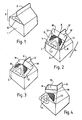
- Figure 1 is a perspective view of the boxed end openable container in the fully closed configuration carrying a pull tab
- Figures 2, 3 and 4 show the container of Figure 1 with the ridge seal partially opened, bent back to form the inverted Y configuration and with the ridge seal separated to form a spout outlet to the container
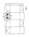
- Figure 5 shows a plan view of a blank for use in the construction of the container of Figure 1
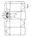
- Figure 6 shows an alternative version of the blank having additional fold lines to assist forming a full length spout to the side wall of the container
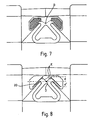
- Figure 7 shows the relationship of the edge of the heat sealed area securing the feet of the pull tab to the container wall to the point of rotation of the shank member
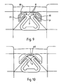
- Figures 8 to 10 show alternative forms of line seals for use in the present invention.
- the container comprises a generally rectangular or square main body portion 1, whose bottom has been closed by conventional box folds or other means, and which contains milk, fruit juice or other fluid or a fluent powder.
- the container is made from a wax or plastic coated paper or card so that it can readily be folded along score lines or the like formed in a sheet blank from which the container is made and the folded configuration secured in place by heat sealing or otherwise adhering the overlapping edge portions of the assembled container.
- the container can be made by blow or extrusion moulding a suitable plastic so that the container is formed as a unitary article with an open top which can then be closed by forming a gable end structure and ridge seal as described above.
- the container is made from a flat blank, this is folded and secured in its desired erected form by heat welding, adhesive or other securing techniques.
- the invention will be described hereinafter in terms of the use of a polyethylene or other thermoplastic polymer coated card as is conventionally used in the manufacture of such containers.
- the upper, terminal portions of the side walls of the container have been folded in upon one another to form a conventional boxed end.
- a V fold is formed in each of two opposed side walls with the apex of each V directed towards the centre line of the container.
- This has the effect of bringing the top edges of the other two side walls together to form a tented end to the container.
- the top edges of the side walls lie against one another to form a ridge 2 lying along a transverse line extending along the line of indentation of the V folds.
- the edges are sealed together by applying heat and pressure using a conventional heat sealing bar or the like to form a comparatively deep transverse seal closure along the ridge 2.
- the depth of this ridge seal is sufficient to incorporate the upper edges of the V folded walls to ensure a fluid tight closure.
- the indented portion of the end of the container is the gabled end 3 and carries a pull tab 10.
- the gabled end wall A carries two fold lines 4 and 5 forming a triangle with its apex at the point at which the wall A is folded to form the V fold as the gabled end to the container is formed.
- To each side of these lines lie inverted triangular areas B which are to form the roof faces of the gabled end of the assembled container and have their bases along the foot of the upper terminal portion of wall A which is to be incorporated into the ridge seal 2.
- Between these triangular areas B is another reversed triangular area C.
- a pull tab cut from a polyethylene/polyester laminate has a pull ring 11 at the proximal end of a shank portion 12. Extending laterally from the shank portion are two symmetrical triangular feet 13. These are secured via the polyethylene layer to the triangular areas B to either side of area C by heat welding or other means, for example adhesive or riveting. The securing extends over the shaded areas shown in the drawings and it will be noted does not extend into the intermediate portion D of the shank between the feet 13.
- the central portion of the pull tab formed from shank 12 and ring pull 11 is not secured to the wall of the container, but is free to bow away from the container during formation of the gabled end to the container and during sealing of the ridge seal. If desired, the proximal end of the ring pull 11 may be tack welded or otherwise temporarily secured to the wall of the container for transport and storage prior to use.
- the shank 12 flexes about a point D when the ring pull 11 is pulled.
- This point D is the point of rotation.
- the edge of the heat seals between the feet 13 and the walls B proximal to the point of rotation D is located closely adjacent to and substantially parallel to the fold lines 4 and 5 so that the included angle between the edge of the heat seal and the longitudinal axis of the shank of the pull tab is about 45°.
- a line drawn from the point of rotation D normal to the edge of the heat seal intersects the edge between its ends and the seal acts as a stop to prevent peeling of the heat seal.
- the heat seal area extends both distally a distance d beyond and proximally a distance d' short of the point of rotation and the ratio d:d' has a value of approximately 1:1.
- Such a container can be assembled from a blank as shown in Figure 5 using conventional techniques and equipment.
- the seal between opposed dry walls along ridge 2 is separated at that end adjacent the pull tab 10 as with a conventional container to produce a ridge which has a T plan shape as shown in Figure 2, having an upright U and wings W to the head of the T shape.
- the seal between the opposed wet walls of the wings is still intact and so the container remains sealed.
- the ridge in the head of the T is bent backwards as shown in Figure 3 to form an inverted Y plan shape to the ridge.
- the user then pulls upon the ring 11 to cause the bonding of the ridge seal at the intersection X of the upright U and the wings W to separate and form the pouring spout 15.
- the pull tab 10 remains below the lip of the spout and is not in contact with the contents of the container, thus reducing the risk of contamination of the contents as they are discharged.
- the spout 15 is comparatively short. It may therefore be desired to add the additional fold lines 20 shown in Figure 6 which extend from the apex of area C to the base of the container to permit the whole of the side wall of the container to bow outwards to form a spout extending for the full height of the container, thus aiding smooth flow of material from the container.
- the feet 13 do not readily separate from the wall material and the user can thus exert considerable force on the bonding of the ridge seal without the feet detaching from the wall.
- the pull tab was in the form of a T so that the heat seals securing the head of the T to the container wall did not extend proximally short of the point of rotation D, the pull tab readily peeled off the wall before the bonding of the ridge seal was separated.
- the feet 13 are secured to the wall by line seals 20 and the lines E from the point of rotation normal to the line of the heat seals intersect the line seal intermediate their ends.
- Such a form of attachment ensures that the pull tab remains secured to the container wall whilst the bonding of the ridge seal is separated.
- Figure 9 shows a set of line seals 30 and 31 conforming to the shape of the outline of the solid heat seal used in Figure 1;
- Figure 10 shows an arcuate line heat seal 40.
- Also shown dotted in Figure 10 is a form of the feet 13 in which they have been cut away to conform to the arcuate shape of the heat seal 40. All these variations of the heat seal of Figure 8 provide good levels of attachment of the pull tab to the container wall.
Landscapes
- Engineering & Computer Science (AREA)
- Mechanical Engineering (AREA)
- Chemical & Material Sciences (AREA)
- Life Sciences & Earth Sciences (AREA)
- Wood Science & Technology (AREA)
- Materials Engineering (AREA)
- Organic Chemistry (AREA)
- Ceramic Engineering (AREA)
- Cartons (AREA)
- Containers And Packaging Bodies Having A Special Means To Remove Contents (AREA)
- Table Devices Or Equipment (AREA)
- Glass Compositions (AREA)
- Catching Or Destruction (AREA)
- Auxiliary Devices For And Details Of Packaging Control (AREA)
- Medicines Containing Plant Substances (AREA)
- Stringed Musical Instruments (AREA)
- Packages (AREA)
Applications Claiming Priority (5)
| Application Number | Priority Date | Filing Date | Title |
|---|---|---|---|
| GBGB9722795.3A GB9722795D0 (en) | 1997-10-29 | 1997-10-29 | Container |
| GB9722795 | 1997-10-29 | ||
| GB9809805 | 1998-05-08 | ||
| GBGB9809805.6A GB9809805D0 (en) | 1998-05-08 | 1998-05-08 | Container |
| PCT/GB1998/003226 WO1999021766A1 (en) | 1997-10-29 | 1998-10-29 | Gable top container with pull tab |
Publications (2)
| Publication Number | Publication Date |
|---|---|
| EP1034111A1 EP1034111A1 (en) | 2000-09-13 |
| EP1034111B1 true EP1034111B1 (en) | 2004-03-17 |
Family
ID=26312506
Family Applications (1)
| Application Number | Title | Priority Date | Filing Date |
|---|---|---|---|
| EP98951568A Expired - Lifetime EP1034111B1 (en) | 1997-10-29 | 1998-10-29 | Gable top container with pull tab |
Country Status (17)
| Country | Link |
|---|---|
| US (1) | US6427908B1 (no) |
| EP (1) | EP1034111B1 (no) |
| JP (1) | JP4090691B2 (no) |
| CN (1) | CN1090133C (no) |
| AT (1) | ATE261854T1 (no) |
| AU (1) | AU745742B2 (no) |
| BR (1) | BR9813325A (no) |
| CA (1) | CA2307852C (no) |
| DE (1) | DE69822501T2 (no) |
| DK (1) | DK1034111T3 (no) |
| ES (1) | ES2217593T3 (no) |
| GB (1) | GB2330825B (no) |
| NO (1) | NO320689B1 (no) |
| PL (1) | PL194877B1 (no) |
| PT (1) | PT1034111E (no) |
| SA (1) | SA99200259B1 (no) |
| WO (1) | WO1999021766A1 (no) |
Families Citing this family (13)
| Publication number | Priority date | Publication date | Assignee | Title |
|---|---|---|---|---|
| US6698650B2 (en) * | 1998-02-06 | 2004-03-02 | Easycarton Limited | Opening means for gable top container |
| US6592024B2 (en) * | 2000-06-19 | 2003-07-15 | Easycarton Limited | Cable top container with pull tab |
| US20050057054A1 (en) * | 2002-01-18 | 2005-03-17 | Hopkins Kenneth Carrol | Pet bandana and sanitary device |
| US20080110918A1 (en) * | 2006-11-15 | 2008-05-15 | Lee Herbert K | Paperboard wipes carton |
| JP6116124B2 (ja) * | 2012-03-15 | 2017-04-19 | シスメックス株式会社 | 生体試料分析装置用の試薬容器及び試薬容器の製造方法 |
| GB201205243D0 (en) | 2012-03-26 | 2012-05-09 | Kraft Foods R & D Inc | Packaging and method of opening |
| GB2511560B (en) | 2013-03-07 | 2018-11-14 | Mondelez Uk R&D Ltd | Improved Packaging and Method of Forming Packaging |
| GB2511559B (en) | 2013-03-07 | 2018-11-14 | Mondelez Uk R&D Ltd | Improved Packaging and Method of Forming Packaging |
| WO2017010088A1 (ja) * | 2015-07-13 | 2017-01-19 | 凸版印刷株式会社 | 包装容器 |
| JP6759694B2 (ja) * | 2016-05-11 | 2020-09-23 | 凸版印刷株式会社 | ゲーベルトップ型包装容器 |
| US10358264B1 (en) * | 2017-05-16 | 2019-07-23 | Facebook Technologies, Llc | Hang tag for the display of boxed items |
| USD839725S1 (en) * | 2017-11-06 | 2019-02-05 | Arkansas River Valley Farms Limited Partnership | Carton with window |
| USD913086S1 (en) * | 2019-01-24 | 2021-03-16 | Arkansas River Valley Farms Limited Partnership | Carton with window |
Family Cites Families (17)
| Publication number | Priority date | Publication date | Assignee | Title |
|---|---|---|---|---|
| US2470199A (en) | 1945-09-07 | 1949-05-17 | Vivian George Stewart | Carton and secondary closure therefor |
| US2687840A (en) | 1951-02-26 | 1954-08-31 | Perga Containers Ltd | Container structure |
| US3204850A (en) | 1964-05-25 | 1965-09-07 | Phillips Petroleum Co | Gable top container |
| US3520464A (en) | 1968-03-11 | 1970-07-14 | William A Pugh Sr | Lift and pull ring container |
| DE2650092C2 (de) * | 1976-10-30 | 1982-09-23 | Milchversorgung Ingolstadt eG, 8070 Ingolstadt | Behälter für fließfähige Stoffe |
| AU8188182A (en) * | 1981-03-23 | 1982-09-30 | Newell, P.T. | Gable top carton with opening tab |
| NL8200798A (nl) * | 1982-02-26 | 1983-09-16 | Dale Adriaan Theodoor | Verpakkingshouder. |
| CA1291092C (en) * | 1988-03-11 | 1991-10-22 | Donald A. Poole | Easy opening gable top carton |
| JPH01147930U (no) * | 1988-04-04 | 1989-10-13 | ||
| US4821950A (en) | 1988-06-20 | 1989-04-18 | Aracelia Sanchez | Liquid container opening device |
| US4874126A (en) | 1989-03-29 | 1989-10-17 | Miller Lawrence G | Container opening device |
| JPH0624438A (ja) * | 1991-02-05 | 1994-02-01 | Tsunetoshi Kobayashi | 紙パック容器の開口方法 |
| GB2253608B (en) * | 1991-02-14 | 1995-02-01 | Tetra Pak Holdings Sa | Opening arrangements for cartons |
| ATE171681T1 (de) * | 1993-05-01 | 1998-10-15 | Procter & Gamble | Vorrichtung zum erleichtern des öffnens für behälter |
| WO1996029253A1 (en) * | 1994-09-12 | 1996-09-26 | Cameron Michael Kent | Sealed container with opening means |
| DK0827478T3 (da) * | 1995-05-23 | 2004-03-08 | Easycarton Ltd | Trækstrimmel til beholder |
| US5871146A (en) * | 1997-04-29 | 1999-02-16 | Onderko; Patricia | Fluid carton container with pull tab |
-
1998
- 1998-10-29 EP EP98951568A patent/EP1034111B1/en not_active Expired - Lifetime
- 1998-10-29 AU AU97528/98A patent/AU745742B2/en not_active Ceased
- 1998-10-29 DK DK98951568T patent/DK1034111T3/da active
- 1998-10-29 GB GB9823652A patent/GB2330825B/en not_active Expired - Fee Related
- 1998-10-29 DE DE69822501T patent/DE69822501T2/de not_active Expired - Lifetime
- 1998-10-29 JP JP2000517883A patent/JP4090691B2/ja not_active Expired - Fee Related
- 1998-10-29 PT PT98951568T patent/PT1034111E/pt unknown
- 1998-10-29 CA CA002307852A patent/CA2307852C/en not_active Expired - Fee Related
- 1998-10-29 WO PCT/GB1998/003226 patent/WO1999021766A1/en active IP Right Grant
- 1998-10-29 PL PL340262A patent/PL194877B1/pl not_active IP Right Cessation
- 1998-10-29 BR BR9813325-0A patent/BR9813325A/pt not_active IP Right Cessation
- 1998-10-29 AT AT98951568T patent/ATE261854T1/de not_active IP Right Cessation
- 1998-10-29 CN CN98810786A patent/CN1090133C/zh not_active Expired - Fee Related
- 1998-10-29 US US09/530,144 patent/US6427908B1/en not_active Expired - Fee Related
- 1998-10-29 ES ES98951568T patent/ES2217593T3/es not_active Expired - Lifetime
-
1999
- 1999-06-20 SA SA99200259A patent/SA99200259B1/ar unknown
-
2000
- 2000-04-28 NO NO20002252A patent/NO320689B1/no not_active IP Right Cessation
Also Published As
| Publication number | Publication date |
|---|---|
| DE69822501D1 (de) | 2004-04-22 |
| CN1278223A (zh) | 2000-12-27 |
| ES2217593T3 (es) | 2004-11-01 |
| DK1034111T3 (da) | 2004-07-12 |
| GB9823652D0 (en) | 1998-12-23 |
| AU745742B2 (en) | 2002-03-28 |
| CN1090133C (zh) | 2002-09-04 |
| ATE261854T1 (de) | 2004-04-15 |
| DE69822501T2 (de) | 2005-02-03 |
| BR9813325A (pt) | 2000-08-22 |
| AU9752898A (en) | 1999-05-17 |
| EP1034111A1 (en) | 2000-09-13 |
| PL194877B1 (pl) | 2007-07-31 |
| SA99200259B1 (ar) | 2006-10-07 |
| GB2330825B (en) | 2000-02-23 |
| NO20002252L (no) | 2000-06-27 |
| NO320689B1 (no) | 2006-01-16 |
| NO20002252D0 (no) | 2000-04-28 |
| GB2330825A (en) | 1999-05-05 |
| CA2307852C (en) | 2007-01-09 |
| PT1034111E (pt) | 2004-08-31 |
| CA2307852A1 (en) | 1999-05-06 |
| US6427908B1 (en) | 2002-08-06 |
| PL340262A1 (en) | 2001-01-29 |
| JP4090691B2 (ja) | 2008-05-28 |
| JP2001520965A (ja) | 2001-11-06 |
| WO1999021766A1 (en) | 1999-05-06 |
Similar Documents
| Publication | Publication Date | Title |
|---|---|---|
| EP1034111B1 (en) | Gable top container with pull tab | |
| EP0827478B1 (en) | Container pull tab | |
| US4712727A (en) | Gable-top container closure system | |
| JPS58125443A (ja) | 包装容器に関する装置 | |
| US4756426A (en) | Gable-top container | |
| US4792048A (en) | Gable-top container | |
| US6592024B2 (en) | Cable top container with pull tab | |
| US4813547A (en) | Gable-top container closure system | |
| EP0286313B1 (en) | Gable-top container | |
| US4869372A (en) | Gable-top container | |
| US5086928A (en) | Flat top end closure for liquid containers | |
| EP0286285B1 (en) | Gable-top container closure system | |
| US6698650B2 (en) | Opening means for gable top container | |
| RU2214954C2 (ru) | Контейнер с коробчатым концом, заготовка и оттяжное ушко для него и способ открывания такого контейнера | |
| GB2253608A (en) | Opening arrangements for cartons | |
| WO1994025352A2 (en) | Improved opening system for containers | |
| MXPA00004242A (en) | Gable top container with pull tab | |
| EP0695264B1 (en) | Improved opening system for containers | |
| EP0439958A1 (en) | Method and apparatus for constructing gable-top container closure system | |
| EP0552928A1 (en) | Container and blank for constructing same |
Legal Events
| Date | Code | Title | Description |
|---|---|---|---|
| PUAI | Public reference made under article 153(3) epc to a published international application that has entered the european phase |
Free format text: ORIGINAL CODE: 0009012 |
|
| 17P | Request for examination filed |
Effective date: 20000523 |
|
| AK | Designated contracting states |
Kind code of ref document: A1 Designated state(s): AT BE CH CY DE DK ES FI FR GB GR IE IT LI LU MC NL PT SE |
|
| 17Q | First examination report despatched |
Effective date: 20001025 |
|
| GRAP | Despatch of communication of intention to grant a patent |
Free format text: ORIGINAL CODE: EPIDOSNIGR1 |
|
| GRAS | Grant fee paid |
Free format text: ORIGINAL CODE: EPIDOSNIGR3 |
|
| GRAA | (expected) grant |
Free format text: ORIGINAL CODE: 0009210 |
|
| AK | Designated contracting states |
Kind code of ref document: B1 Designated state(s): AT BE CH CY DE DK ES FI FR GB GR IE IT LI LU MC NL PT SE |
|
| REG | Reference to a national code |
Ref country code: GB Ref legal event code: FG4D |
|
| REG | Reference to a national code |
Ref country code: CH Ref legal event code: EP |
|
| REG | Reference to a national code |
Ref country code: IE Ref legal event code: FG4D |
|
| REF | Corresponds to: |
Ref document number: 69822501 Country of ref document: DE Date of ref document: 20040422 Kind code of ref document: P |
|
| RBV | Designated contracting states (corrected) |
Designated state(s): AT BE CH CY DE DK ES FI FR GR IE IT LI LU MC NL PT SE |
|
| RAP2 | Party data changed (patent owner data changed or rights of a patent transferred) |
Owner name: EASYCARTON LIMITED |
|
| REG | Reference to a national code |
Ref country code: SE Ref legal event code: TRGR |
|
| REG | Reference to a national code |
Ref country code: CH Ref legal event code: NV Representative=s name: KIRKER & CIE SA |
|
| REG | Reference to a national code |
Ref country code: DK Ref legal event code: T3 |
|
| REG | Reference to a national code |
Ref country code: GR Ref legal event code: EP Ref document number: 20040401862 Country of ref document: GR |
|
| NLT2 | Nl: modifications (of names), taken from the european patent patent bulletin |
Owner name: EASYCARTON LIMITED |
|
| REG | Reference to a national code |
Ref country code: PT Ref legal event code: SC4A Free format text: AVAILABILITY OF NATIONAL TRANSLATION Effective date: 20040615 |
|
| REG | Reference to a national code |
Ref country code: ES Ref legal event code: FG2A Ref document number: 2217593 Country of ref document: ES Kind code of ref document: T3 |
|
| ET | Fr: translation filed | ||
| PLBE | No opposition filed within time limit |
Free format text: ORIGINAL CODE: 0009261 |
|
| STAA | Information on the status of an ep patent application or granted ep patent |
Free format text: STATUS: NO OPPOSITION FILED WITHIN TIME LIMIT |
|
| REG | Reference to a national code |
Ref country code: HK Ref legal event code: WD Ref document number: 1032574 Country of ref document: HK |
|
| 26N | No opposition filed |
Effective date: 20041220 |
|
| PGFP | Annual fee paid to national office [announced via postgrant information from national office to epo] |
Ref country code: MC Payment date: 20081117 Year of fee payment: 11 Ref country code: LU Payment date: 20081030 Year of fee payment: 11 |
|
| PGFP | Annual fee paid to national office [announced via postgrant information from national office to epo] |
Ref country code: ES Payment date: 20081127 Year of fee payment: 11 Ref country code: AT Payment date: 20081031 Year of fee payment: 11 |
|
| PGFP | Annual fee paid to national office [announced via postgrant information from national office to epo] |
Ref country code: PT Payment date: 20090317 Year of fee payment: 11 |
|
| PGFP | Annual fee paid to national office [announced via postgrant information from national office to epo] |
Ref country code: CY Payment date: 20081117 Year of fee payment: 11 |
|
| PG25 | Lapsed in a contracting state [announced via postgrant information from national office to epo] |
Ref country code: IT Free format text: LAPSE BECAUSE OF NON-PAYMENT OF DUE FEES Effective date: 20081029 |
|
| PG25 | Lapsed in a contracting state [announced via postgrant information from national office to epo] |
Ref country code: MC Free format text: LAPSE BECAUSE OF NON-PAYMENT OF DUE FEES Effective date: 20091031 |
|
| PG25 | Lapsed in a contracting state [announced via postgrant information from national office to epo] |
Ref country code: PT Free format text: LAPSE BECAUSE OF NON-PAYMENT OF DUE FEES Effective date: 20100429 |
|
| PG25 | Lapsed in a contracting state [announced via postgrant information from national office to epo] |
Ref country code: AT Free format text: LAPSE BECAUSE OF NON-PAYMENT OF DUE FEES Effective date: 20091029 |
|
| PG25 | Lapsed in a contracting state [announced via postgrant information from national office to epo] |
Ref country code: CY Free format text: LAPSE BECAUSE OF NON-PAYMENT OF DUE FEES Effective date: 20091029 |
|
| PGFP | Annual fee paid to national office [announced via postgrant information from national office to epo] |
Ref country code: FR Payment date: 20101110 Year of fee payment: 13 |
|
| PGFP | Annual fee paid to national office [announced via postgrant information from national office to epo] |
Ref country code: CH Payment date: 20101029 Year of fee payment: 13 |
|
| PGFP | Annual fee paid to national office [announced via postgrant information from national office to epo] |
Ref country code: BE Payment date: 20101105 Year of fee payment: 13 |
|
| REG | Reference to a national code |
Ref country code: ES Ref legal event code: FD2A Effective date: 20110411 |
|
| PG25 | Lapsed in a contracting state [announced via postgrant information from national office to epo] |
Ref country code: LU Free format text: LAPSE BECAUSE OF NON-PAYMENT OF DUE FEES Effective date: 20091029 |
|
| PG25 | Lapsed in a contracting state [announced via postgrant information from national office to epo] |
Ref country code: ES Free format text: LAPSE BECAUSE OF NON-PAYMENT OF DUE FEES Effective date: 20110329 |
|
| PGRI | Patent reinstated in contracting state [announced from national office to epo] |
Ref country code: IT Effective date: 20110616 |
|
| PG25 | Lapsed in a contracting state [announced via postgrant information from national office to epo] |
Ref country code: ES Free format text: LAPSE BECAUSE OF NON-PAYMENT OF DUE FEES Effective date: 20091030 |
|
| BERE | Be: lapsed |
Owner name: *EASYCARTON LTD Effective date: 20111031 |
|
| REG | Reference to a national code |
Ref country code: CH Ref legal event code: PL |
|
| REG | Reference to a national code |
Ref country code: FR Ref legal event code: ST Effective date: 20120629 |
|
| PG25 | Lapsed in a contracting state [announced via postgrant information from national office to epo] |
Ref country code: BE Free format text: LAPSE BECAUSE OF NON-PAYMENT OF DUE FEES Effective date: 20111031 Ref country code: CH Free format text: LAPSE BECAUSE OF NON-PAYMENT OF DUE FEES Effective date: 20111031 Ref country code: LI Free format text: LAPSE BECAUSE OF NON-PAYMENT OF DUE FEES Effective date: 20111031 |
|
| PG25 | Lapsed in a contracting state [announced via postgrant information from national office to epo] |
Ref country code: FR Free format text: LAPSE BECAUSE OF NON-PAYMENT OF DUE FEES Effective date: 20111102 |
|
| REG | Reference to a national code |
Ref country code: PT Ref legal event code: MM4A Free format text: LAPSE DUE TO NON-PAYMENT OF FEES Effective date: 20100429 |
|
| PGFP | Annual fee paid to national office [announced via postgrant information from national office to epo] |
Ref country code: DK Payment date: 20131011 Year of fee payment: 16 |
|
| PGFP | Annual fee paid to national office [announced via postgrant information from national office to epo] |
Ref country code: DE Payment date: 20131010 Year of fee payment: 16 Ref country code: SE Payment date: 20131018 Year of fee payment: 16 |
|
| PGFP | Annual fee paid to national office [announced via postgrant information from national office to epo] |
Ref country code: GR Payment date: 20131009 Year of fee payment: 16 Ref country code: FI Payment date: 20131022 Year of fee payment: 16 |
|
| PGFP | Annual fee paid to national office [announced via postgrant information from national office to epo] |
Ref country code: IE Payment date: 20141031 Year of fee payment: 17 |
|
| PGFP | Annual fee paid to national office [announced via postgrant information from national office to epo] |
Ref country code: NL Payment date: 20141031 Year of fee payment: 17 |
|
| REG | Reference to a national code |
Ref country code: DE Ref legal event code: R119 Ref document number: 69822501 Country of ref document: DE |
|
| REG | Reference to a national code |
Ref country code: SE Ref legal event code: EUG |
|
| REG | Reference to a national code |
Ref country code: GR Ref legal event code: ML Ref document number: 20040401862 Country of ref document: GR Effective date: 20150505 |
|
| PG25 | Lapsed in a contracting state [announced via postgrant information from national office to epo] |
Ref country code: SE Free format text: LAPSE BECAUSE OF NON-PAYMENT OF DUE FEES Effective date: 20141030 Ref country code: DE Free format text: LAPSE BECAUSE OF NON-PAYMENT OF DUE FEES Effective date: 20150501 Ref country code: FI Free format text: LAPSE BECAUSE OF NON-PAYMENT OF DUE FEES Effective date: 20141029 |
|
| REG | Reference to a national code |
Ref country code: DK Ref legal event code: EBP Effective date: 20141031 |
|
| PG25 | Lapsed in a contracting state [announced via postgrant information from national office to epo] |
Ref country code: GR Free format text: LAPSE BECAUSE OF NON-PAYMENT OF DUE FEES Effective date: 20150505 |
|
| PG25 | Lapsed in a contracting state [announced via postgrant information from national office to epo] |
Ref country code: DK Free format text: LAPSE BECAUSE OF NON-PAYMENT OF DUE FEES Effective date: 20141031 |
|
| PGFP | Annual fee paid to national office [announced via postgrant information from national office to epo] |
Ref country code: IT Payment date: 20151023 Year of fee payment: 18 |
|
| REG | Reference to a national code |
Ref country code: NL Ref legal event code: MM Effective date: 20151101 |
|
| REG | Reference to a national code |
Ref country code: IE Ref legal event code: MM4A |
|
| PG25 | Lapsed in a contracting state [announced via postgrant information from national office to epo] |
Ref country code: NL Free format text: LAPSE BECAUSE OF NON-PAYMENT OF DUE FEES Effective date: 20151101 |
|
| PG25 | Lapsed in a contracting state [announced via postgrant information from national office to epo] |
Ref country code: IE Free format text: LAPSE BECAUSE OF NON-PAYMENT OF DUE FEES Effective date: 20151029 |
|
| PG25 | Lapsed in a contracting state [announced via postgrant information from national office to epo] |
Ref country code: IT Free format text: LAPSE BECAUSE OF NON-PAYMENT OF DUE FEES Effective date: 20161029 |
|
| PG25 | Lapsed in a contracting state [announced via postgrant information from national office to epo] |
Ref country code: CY Free format text: LAPSE BECAUSE OF FAILURE TO SUBMIT A TRANSLATION OF THE DESCRIPTION OR TO PAY THE FEE WITHIN THE PRESCRIBED TIME-LIMIT Effective date: 20040317 |
|
| RIC2 | Information provided on ipc code assigned after grant |
Ipc: B65D 5/06 20060101AFI19990518BHEP |