EP1033245A1 - Sprühfeuchtwerk mit hoher effektiver Sprühfrequenz - Google Patents
Sprühfeuchtwerk mit hoher effektiver Sprühfrequenz Download PDFInfo
- Publication number
- EP1033245A1 EP1033245A1 EP00102164A EP00102164A EP1033245A1 EP 1033245 A1 EP1033245 A1 EP 1033245A1 EP 00102164 A EP00102164 A EP 00102164A EP 00102164 A EP00102164 A EP 00102164A EP 1033245 A1 EP1033245 A1 EP 1033245A1
- Authority
- EP
- European Patent Office
- Prior art keywords
- spray
- nozzles
- spray nozzles
- rows
- individual phase
- Prior art date
- Legal status (The legal status is an assumption and is not a legal conclusion. Google has not performed a legal analysis and makes no representation as to the accuracy of the status listed.)
- Granted
Links
- 238000005507 spraying Methods 0.000 title claims 3
- 238000013016 damping Methods 0.000 title 1
- 239000007921 spray Substances 0.000 claims abstract description 177
- 230000001360 synchronised effect Effects 0.000 claims abstract description 14
- 230000010363 phase shift Effects 0.000 claims description 24
- 238000007639 printing Methods 0.000 claims description 16
- 238000000034 method Methods 0.000 claims description 7
- 230000003213 activating effect Effects 0.000 claims 1
- 238000006073 displacement reaction Methods 0.000 abstract 2
- 238000009826 distribution Methods 0.000 description 3
- 238000005516 engineering process Methods 0.000 description 3
- 230000004913 activation Effects 0.000 description 2
- 238000007645 offset printing Methods 0.000 description 2
- 230000000737 periodic effect Effects 0.000 description 2
- 230000002411 adverse Effects 0.000 description 1
- 230000000712 assembly Effects 0.000 description 1
- 238000000429 assembly Methods 0.000 description 1
- 238000004040 coloring Methods 0.000 description 1
- 230000001934 delay Effects 0.000 description 1
- 230000000694 effects Effects 0.000 description 1
- 238000009434 installation Methods 0.000 description 1
- 230000001788 irregular Effects 0.000 description 1
- 238000004519 manufacturing process Methods 0.000 description 1
- 239000003595 mist Substances 0.000 description 1
- 238000001556 precipitation Methods 0.000 description 1
- 239000005871 repellent Substances 0.000 description 1
- 230000000717 retained effect Effects 0.000 description 1
- 239000000758 substrate Substances 0.000 description 1
- XLYOFNOQVPJJNP-UHFFFAOYSA-N water Substances O XLYOFNOQVPJJNP-UHFFFAOYSA-N 0.000 description 1
Images



Classifications
-
- B—PERFORMING OPERATIONS; TRANSPORTING
- B41—PRINTING; LINING MACHINES; TYPEWRITERS; STAMPS
- B41F—PRINTING MACHINES OR PRESSES
- B41F7/00—Rotary lithographic machines
- B41F7/20—Details
- B41F7/24—Damping devices
- B41F7/30—Damping devices using spraying elements
Definitions
- the present invention relates generally to a spray device for a printing press, in particular for a web-fed offset printing machine, according to the preamble of Claim 1.
- Controlling the amount and distribution of dampening solution is extremely important: At insufficient moistening there is a risk that the ink will not print Spreads sections. If the humidification is too strong, the excess dampening solution must be used caught and derived, and there is a risk of damage to the Too much moisture. An even, precisely dosed Applying dampening solution is therefore desirable.
- the spray dampening system for a printing press comprises a large number of spray nozzles, which in particular on a surface of a target element a dampening roller in a printing unit directed spray jets.
- Each of the spray nozzles goes through a spray cycle with a specified spray frequency and an individual Spray phase shift, the individual spray phase shifts such are synchronized that the effective frequency of the applied to the surface Spray jets are higher than the specified frequency.
- dampening solution in one Spray dampening system of a printing press uses a variety of dampening solutions Spray nozzles sprayed onto a surface of a target element in the printing unit, each the spray nozzles a spray cycle with a predetermined frequency and an individual Spray phase shift goes through.
- the individual spray phase shifts are synchronized so that the effective frequency of the applied to the surface Spray jets are higher than the specified frequency.
- the present invention provides an increased effective frequency of Spray jets reached, which goes beyond the limits of individual nozzles.
- Spray dampening systems and the quality of the dampening solution application can be significantly increased.
- the benefits of a pulsed spray dampening system are retained while the one achieved
- the result of the moistening is equivalent to a continuous dampening solution application.
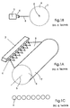
- FIG. 1A shows a perspective view of a spray dampening system of the prior art with a spray bar 2, spray nozzles 4 and a generally cylindrical one Longitudinal axis 5 rotatable roller 6.
- a pressurized, over the spray bar 2nd supplied dampening solution is in the form of spray or spray mist 8 on the Moving surface 7 of the roller 6 applied by the spray nozzles 4 periodically be opened and closed.
- the spray nozzles generally go through the cycle at the same time and with a common frequency, which is based on various parameters, e.g. B. the printing speed can be varied.
- Figure 1B shows a cross section of the spray dampening unit of the prior art shown in FIG. 1A Technology. From Fig. 1C, as well as from Fig. 1A and 1B it can be seen that the spray nozzles of the spray dampening system of the prior art in a to the longitudinal axis 5 of the roller 6 in Are arranged essentially parallel row.
- 2A, 2B and 2C is an embodiment of an inventive Spray dampening system shown.
- a series of spray nozzles 40a, 40b and 40c are arranged, each with a fountain solution spray 80 on the surface 62 of the rotating about the longitudinal axis 64, in Align substantially cylindrical roller 60.
- the spray nozzles are above the surface 62 arranged in a rectangular array of M x N nozzles, as shown in Fig. 2C M is the number of rows and N is the number of columns. In the illustrated For example, M is three and N is eight.
- the spray nozzle assemblies 40a, 40b and 40c are activated periodically, i.e. H. with a predetermined frequency f opened and closed. According to the present In the exemplary embodiment, the nozzles are synchronized as follows:
- the nozzle arrangements thus spray one after the other, starting with the nozzle arrangement 40a.
- the sequence is preferably cyclical, ie 40a, 40b, 40c, 40a, 40b, 40c etc.
- the phase shifts between the nozzle arrangements 40a and 40b and between the nozzle arrangements 40b and 40c are preferably identical, so that the time period between the activation of the spray nozzle arrangements is always the same is.
- the nozzles of the different nozzle arrangements preferably have the same pulse length, ie the time during which the nozzles are open is preferably the same for all nozzles.
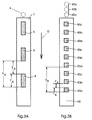
- FIG. 3A shows a schematic top view of a developed section of the surface 7 of the roller 6 of the spray dampening system of the prior art shown and described in FIGS. 1A, 1B and 1C.
- the spray areas 9 symbolize in a simplified manner the dampening solution application generated by means of individual, sequential spray jets from the nozzles 4 on the surface 7, while the latter moves past the nozzle 4 in the direction D due to the rotary movement of the roller 6.
- X A shows the cycle length of the nozzle 4.
- X A depends on the frequency of the nozzle and the (tangential) surface speed of the surface 7.
- the length Y A of the spray area and the length Z A of the dry area depend on the working cycle of the nozzle and the surface speed of the surface 7.
- FIG. 3B shows a schematic top view of a developed section of the surface 62 of the roller 60 of the embodiment of the spray dampening device according to the invention shown in FIGS. 2A, 2B and 2C and described above.
- Three spray nozzles 40a, 40b and 40c are shown, which represent a column of the M x N spray nozzle arrangement shown in FIG. 2C.
- the spray areas 90a, 90b and 90c represent, in simplified form, the application of dampening solution to the surface 62 by the individual fountain solution spray jets which are emitted one after the other from the spray nozzles 40a, 40b and 40c, while the latter moves in the direction D due to the rotary movement of the roller 60 moved past the nozzles.
- the nozzles 40a, 40b and 40c are opened and closed cyclically one after the other, this being done out of phase and preferably synchronized in time.
- the frequency f of one nozzle is the same for all nozzles 40a, 40b and 40c.
- X B shows the cycle length of a nozzle.
- Y B and Z B represent the length of a spray area and a dry area, respectively, on surface 62.
- the frequency f of the nozzle cycle is equal to the frequency of the prior art spray dampener shown in Figure 3A, and the (tangential) surface speed is Area 62 is equal to the surface speed of area 7 of the prior art spray dampener shown in FIG.
- the cycle length X B is equal to the cycle length X A of the prior art spray dampener shown in FIG. 3A.
- the cycle time of the nozzles 40a, 40b and 40c is selected such that the length Y B of the spray area is one third of the length Y A of the spray area of the prior art spray dampening device shown in FIG. 3A and the length Z B of the dry one Area corresponds to a third of the length Z A of the dry area of the prior art spray dampening device shown in FIG. 3A.
- the spray nozzles are in groups 41 on one Spray bar 20 arranged, each group, for example, three spray nozzles 41d, 41e and 41f includes.
- the three nozzles in a group are aligned in the same way, so that they are in the Spray on substantially the same area of surface 62 of roller 60 judge.
- the three nozzles of each group are out of phase activated one after the other.
- the spray nozzle 41d is first opened and closed again. A predetermined time later, the spray nozzle 41e is opened and closed again, and again the same period later, the spray nozzle 41f opened and closed again.
- the three spray nozzles of the other groups 41 are preferably according to the same time delay pattern, i.e. H. at the same time and with same frequency, activated. In other embodiments of the present invention different delay patterns and nozzle frequencies can be used.
- Each spray nozzle group is one of the embodiments of the present described herein Spray dampening according to the invention produces an essentially that in FIG. 3B corresponding spray pattern shown, but the nozzles are arranged to save space.
- FIG. 5B a plurality of spray bars 20 corresponding to the embodiment shown in FIG. 5A Groups 41 of three nozzles 41d, 41e and 41f are provided, so that a rectangular M x N arrangement of nozzle groups in M rows and N columns results.
- 5B is one exemplary arrangement of three rows a, b and c of spray strips 20a, 20b and 20c shown.
- the nozzles of each group preferably activated with a time delay pattern and are preferably with the corresponding nozzles of another group, as described above with reference to FIG. 5A and a single spray bar 20 is described.
- the nozzle rows a, b and c are preferably activated with a phase shift relative to one another, so that the nozzles on the spray bar 20b are synchronized to be one predetermined period of time after the corresponding nozzles on the spray bar 20a activated and the nozzles on the spray bar 20c are synchronized to be one predetermined period of time after the corresponding nozzles on the spray bar 20b activated become.
- the time delays between the spray bars are preferably identical.
- the phase shift based on the Nozzle group columns occur so that the nozzle groups in the individual columns of the M x N arrangement are out of phase with respect to another column. That way you can the nozzle arrangement uses a two-dimensional phase shift.
- nozzle arrangements are also conceivable, e.g. B. in triangular shape, as well as alternative Combinations of nozzle groups in regular or irregular geometric Arrangements with different numbers of nozzles per group. It can too different phase shift patterns, e.g. B. also with different working cycles of the nozzles.
Landscapes
- Engineering & Computer Science (AREA)
- Mechanical Engineering (AREA)
- Rotary Presses (AREA)
- Nozzles (AREA)
Abstract
Description
- Fig. 1A
- eine perspektivische Darstellung des Sprühfeuchtwerks des Standes der Technik;
- Fig. 1B
- einen Querschnitt eines Sprühfeuchtwerks des Standes der Technik von Fig. 1A;
- Fig. 1C
- eine schematische Darstellung der Sprühdüsenanordnung des Sprühfeuchtwerks nach dem Stand der Technik von Fig. 1A;
- Fig. 2A
- eine perspektivische Darstellung einer Ausführungsform eines Sprühfeuchtwerks gemäß der vorliegenden Erfindung;
- Fig. 2B
- einen schematischen Querschnitt des Sprühfeuchtwerks von Fig. 2A;
- Fig. 2C
- eine schematische Ansicht der Sprühdüsenanordnung des Sprühfeuchtwerks von Fig. 2A;
- Fig. 3A
- eine schematische Draufsicht auf einen abgewickelten Abschnitt der Oberfläche einer Walze des in Fig. 1A gezeigten Sprühfeuchtwerks des Standes der Technik zur Darstellung der Sprühdichte der Vorrichtung;
- Fig. 3B
- eine schematische Draufsicht auf einen abgewickelten Abschnitt der Oberfläche einer Walze des in Fig. 2A gezeigten erfindungsgemäßen Sprühfeuchtwerks, zur Darstellung der Sprühdichte der Vorrichtung;
- Fig. 4
- eine schematische Ansicht der Sprühdüsenanordnung gemäß einer weiteren Ausführungsform der vorliegenden Erfindung mit einer Anordnung von versetzt angeordneten Sprühdüsen;
- Fig. 5A
- eine schematische Ansicht der Sprühdüsenanordnung gemäß einer weiteren Ausführungsform der vorliegenden Erfindung mit in Gruppen angeordneten Sprühdüsen; und
- Fig. 5B
- eine schematische Ansicht der Sprühdüsenanordnung gemäß einer weiteren Ausführungsform der vorliegenden Erfindung mit drei Reihen von Sprühdüsengruppen.
- 2
- Sprühleiste
- 4
- Sprühdüsen
- 5
- Längsachse
- 6
- zylindrische Walze
- 7
- Oberfläche
- 8
- Sprühstrahl
- 9
- Sprühbereich
- 20
- Sprühleiste
- 20a, 20b, 20c
- Sprühleiste
- 41
- Sprühdüsengruppe
- 60
- zylindrische Walze
- 62
- Oberfläche
- 64
- Längsachse
- 80
- Sprühstrahl
- 40a, 40b, 40c
- Sprühdüse
- 41d, 41e, 41f
- Sprühdüse
- 90a, 90b, 90c
- Sprühbereich
- D
- Drehrichtung
- M
- Anzahl der Düsenreihen
- N
- Anzahl der Düsenspalten
- XA
- Zykluslänge der Düse 4
- XB
- Zykluslänge der Düsen 40a, 40b, 40c
- YA
- Länge des Sprühbereichs
- YB
- Länge des Sprühbereichs
- ZB
- Länge des trockenen Bereichs
- ZA
- Länge des trockenen Bereichs
Claims (13)
- Sprühvorrichtung für eine Druckmaschine mit einer Vielzahl von Sprühdüsen (40a, 40b, 40c, 41d, 41e, 41f) zum Aufbringen von Sprühstrahlen (80) auf eine Oberfläche (62) eines Zielelements (60) der Druckmaschine,
dadurch gekennzeichnet,dass jede der Sprühdüsen (40a, 40b, 40c, 41d, 41e, 41f) einen Zyklus mit einer vorgegebenen Frequenz und einer vorgegebenen Phasenverschiebung durchläuft,
wobei die individuellen Phasenverschiebungen der Düsen derart synchronisiert sind, dass die effektive Frequenz der auf die Oberfläche (62) gerichteten Sprühstrahlen (80) größer als die vorgegebene Frequenz ist. - Vorrichtung nach Anspruch 1,
dadurch gekennzeichnet,dass die Sprühdüsen in einer Vielzahl M von Reihen angeordnet sind, wobei M eine ganze Zahl ist, dass jede der Reihen mindestens eine Sprühdüse (40a, 40b, 40c, 41d, 41e, 41f) aufweist, und dass die individuelle Phasenverschiebung der mindestens einen Sprühdüse (40a, 40b, 40c, 41d, 41e, 41f) einer Reihe der individuellen Phasenverschiebung der Reihe entspricht, wobei die individuellen Phasenverschiebungen der Reihen derart synchronisiert sind, dass die effektive Frequenz der auf die Oberfläche (62) gerichteten Sprühstrahlen (80) dem M-fachen der vorgegebenen Frequenz entspricht. - Vorrichtung nach Anspruch 2,
dadurch gekennzeichnet,dass sich die Oberfläche (62) bezüglich der Sprühdüsen (40a, 40b, 40c, 41d, 41e, 41f) bewegt und dass die Vielzahl von Sprühdüsenreihen im Wesentlichen orthogonal zu der Bewegungsrichtung (D) des Zielelements (60) verlaufen. - Vorrichtung nach Anspruch 1,
dadurch gekennzeichnet,dass das Zielelement (60) eine rotierende Walze ist. - Vorrichtung nach Anspruch 1,
dadurch gekennzeichnet,dass die Sprühdüsen (40a, 40b, 40c, 41d, 41e, 41f) in einer Vielzahl von Reihen angeordnet sind, so dass sie eine Sprühdüsenanordnung bilden. - Vorrichtung nach Anspruch 1,
dadurch gekennzeichnet,dass die Sprühdüsen (41d, 41e, 41f) in mindestens einer Reihe angeordnet sind unddass die Sprühdüsen (41d, 41e, 41f) einer jeden der mindestens einen Reihe in einer Vielzahl von Gruppen (41) angeordnet sind, wobei jede Gruppe (41) mindestens zwei Sprühdüsen (41d, 41e, 41f) umfasst. - Vorrichtung nach Anspruch 6,
dadurch gekennzeichnet,dass die Sprühdüsen (41d, 41e, 41f) einer Gruppe (41) derart ausgerichtet sind,dass sie einen Sprühstrahl (80) auf im Wesentlichen denselben Bereich richten. - Vorrichtung nach Anspruch 6, dadurch gekennzeichnet,dass jede Gruppe (41) eine identische Anzahl von Sprühdüsen (41d, 41e, 41f) umfasst und dass die Phasenverschiebungen der Sprühdüsen (41d, 41e, 41f) in einer Gruppe (41) derart synchronisiert sind, dass die effektive Frequenz der auf die Oberfläche (62) gerichteten Sprühstrahlen (80) der vorgegebenen Frequenz multipliziert mit der Anzahl der Sprühdüsen (41d, 41e, 41f) pro Gruppe (41) entspricht.
- Vorrichtung nach Anspruch 1,
dadurch gekennzeichnet,dass die Oberfläche (62) eine Walze ist, dass die Sprühdüsen (40a, 40b, 40c, 41d, 41e, 41f) in einer Vielzahl von M Reihen angeordnet sind, wobei M eine ganze Zahl ist, dass die Reihen orthogonal zu einer Längsachse der Walze verlaufen und mindestens eine Sprühdüse (40a, 40b, 40c, 41d, 41e, 41f) umfassen, deren individuelle Phasenverschiebung der individuellen Phasenverschiebung einer Reihe entspricht, wobei die individuellen Phasenverschiebungen der Reihen derart synchronisiert sind, dass die effektive Frequenz der auf die Oberfläche (62) des Zielelements (60) gerichteten Sprühstrahlen (80) dem M-fachen der vorgegebenen Frequenz entspricht. - Verfahren zum Aufbringen von Feuchtmittel in einer Druckmaschine
gekennzeichnet durch
die folgenden Verfahrensschritte:Aufsprühen eines Feuchtmittels in Form von Sprühstrahlen auf eine Oberfläche eines Zielelements der Druckmaschine mittels einer Vielzahl von Sprühdüsen;und Aktivieren der Sprühdüsen mit einer vorgegebenen Frequenz und einer individuellen Phasenverschiebung, wobei die individuellen Phasenverschiebungen derart synchronisiert sind, dass die effektive Frequenz der auf die Oberfläche gerichteten Sprühstrahlen größer als die vorgegebene Frequenz ist. - Verfahren nach Anspruch 10,
dadurch gekennzeichnet,dass die Sprühdüsen in einer Vielzahl von M Reihen angeordnet sind, dass M eine ganze Zahl ist, dass die Reihen jeweils mindestens eine Sprühdüse umfassen, dass die individuelle Phasenverschiebung der mindestens einen Sprühdüse in einer Reihe der individuellen Phasenverschiebung einer Reihe entspricht und die individuellen Phasenverschiebungen der Reihen derart synchronisiert sind, dass die effektive Frequenz der auf die Oberfläche gerichteten Sprühstrahlen das M-fache der vorgegebenen Frequenz beträgt. - Verfahren nach Anspruch 11,
dadurch gekennzeichnet,dass sich die Oberfläche bezüglich der Sprühdüsen bewegt und dass die Vielzahl von Sprühdüsenreihen im Wesentlichen orthogonal zu der Bewegungsrichtung der sich bewegenden Oberfläche verlaufen. - Verfahren nach einem der Ansprüche 10 bis 12,
dadurch gekennzeichnet,dass das Zielelement eine Walze ist.
Applications Claiming Priority (2)
| Application Number | Priority Date | Filing Date | Title |
|---|---|---|---|
| US259927 | 1999-03-01 | ||
| US09/259,927 US6327974B1 (en) | 1999-03-01 | 1999-03-01 | Spray dampening device having high effective spray frequency and method of using |
Publications (2)
| Publication Number | Publication Date |
|---|---|
| EP1033245A1 true EP1033245A1 (de) | 2000-09-06 |
| EP1033245B1 EP1033245B1 (de) | 2002-05-15 |
Family
ID=22987021
Family Applications (1)
| Application Number | Title | Priority Date | Filing Date |
|---|---|---|---|
| EP00102164A Expired - Lifetime EP1033245B1 (de) | 1999-03-01 | 2000-02-08 | Sprühfeuchtwerk mit hoher effektiver Sprühfrequenz |
Country Status (5)
| Country | Link |
|---|---|
| US (1) | US6327974B1 (de) |
| EP (1) | EP1033245B1 (de) |
| JP (1) | JP2000246864A (de) |
| AT (1) | ATE217577T1 (de) |
| DE (2) | DE50000164D1 (de) |
Cited By (4)
| Publication number | Priority date | Publication date | Assignee | Title |
|---|---|---|---|---|
| EP2117843B1 (de) * | 2006-11-24 | 2012-02-01 | manroland AG | Verfahren zum betreiben eines feuchtwerks, feuchtwerk sowie druckwerk |
| DE102014218451A1 (de) | 2014-09-15 | 2016-03-17 | Koenig & Bauer Ag | Vorrichtungen und Verfahren zur Einstellung und/oder Änderung eines sich in Richtung Druckbreite erstreckenden Profils in der Feuchtmittelführung sowie Druckwerk mit einer Vorrichtung zur Einstellung und/oder Änderung des Profils |
| WO2016041642A1 (de) * | 2014-09-15 | 2016-03-24 | Koenig & Bauer Ag | Einstellung und/oder änderung eines profils in der feuchtmittelführung eines druckwerks |
| DE102014218452A1 (de) | 2014-09-15 | 2016-04-07 | Koenig & Bauer Ag | Vorrichtungen und Verfahren zur Einstellung und/oder Änderung eines sich in Richtung Druckbreite erstreckenden Profils in der Feuchtmittelführung sowie Druckwerk mit einer Vorrichtung zur Einstellung und/oder Änderung des Profils |
Families Citing this family (8)
| Publication number | Priority date | Publication date | Assignee | Title |
|---|---|---|---|---|
| US6758938B1 (en) * | 1999-08-31 | 2004-07-06 | Micron Technology, Inc. | Delivery of dissolved ozone |
| DE10258325B4 (de) * | 2002-10-25 | 2005-08-18 | Koenig & Bauer Ag | Verfahren zur Einstellung eines Sprühfeuchtwerks |
| DE10317470B4 (de) * | 2003-04-16 | 2005-10-06 | Technotrans Ag | Sprühfeuchtwerk |
| KR20050041907A (ko) * | 2003-10-31 | 2005-05-04 | 발드윈-저팬 리미티드 | 축임물 공급장치 |
| US20070045453A1 (en) * | 2005-08-23 | 2007-03-01 | Goss International Americas, Inc. | Central manifold supply for spray bar |
| US20100064917A1 (en) * | 2006-11-24 | 2010-03-18 | Goss International Montataire Sa | Printing machine and corresponding method |
| DE102007043857A1 (de) * | 2007-09-14 | 2009-03-19 | Manroland Ag | Verfahren zum Betreiben einer Rollendruckmaschine |
| DE102018104534B3 (de) | 2018-02-28 | 2019-04-25 | Baldwin Technology Gmbh | Sprührohr und druckmaschinenwalzen-reinigungsvorrichtung mit einem sprührohr |
Citations (5)
| Publication number | Priority date | Publication date | Assignee | Title |
|---|---|---|---|---|
| US4469024A (en) * | 1982-10-18 | 1984-09-04 | Press Machinery Corporation | Fluid dispensing apparatus such as spray dampener for printing press and method of dispensing |
| US4649818A (en) * | 1985-07-22 | 1987-03-17 | Ryco Graphic Manufacturing, Inc. | Variable frequency pulsed spray dampening system |
| US4708058A (en) * | 1985-10-10 | 1987-11-24 | Smith Rpm Corporation | Water pulse spray dampening system and method for printing presses |
| EP0325381A2 (de) * | 1988-01-19 | 1989-07-26 | Jimek Ab | Eine Kontrollvorrichtung zur Betätigung einer Befeuchtungssprühanordnung |
| EP0341384A2 (de) * | 1988-05-09 | 1989-11-15 | Rockwell International Corporation | Durch Mikroprozessor gesteuerte Anfeuchtvorrichtung einer Druckmaschine |
Family Cites Families (8)
| Publication number | Priority date | Publication date | Assignee | Title |
|---|---|---|---|---|
| US4064801A (en) | 1975-08-12 | 1977-12-27 | Ryco Graphic Manufacturing, Inc. | Spray dampening system for offset printing |
| US4198907A (en) | 1977-05-05 | 1980-04-22 | Ryco Graphic Manufacturing Inc. | Spray dampening system for offset printing with page control assembly |
| US4211258A (en) | 1977-05-05 | 1980-07-08 | Ryco Graphic Manufacturing, Inc. | Spray dampening system for offset printing with page control assembly |
| US4465714A (en) * | 1982-08-11 | 1984-08-14 | Fmc Corporation | Sequentially pulsed spraying system |
| US4815375A (en) | 1985-07-22 | 1989-03-28 | Ryco Graphic Manufacturing, Inc. | Spray dampening system having alternate application control |
| DE3545535A1 (de) * | 1985-12-21 | 1987-07-02 | Mailaender Fa J G | Verfahren zum auftragen von feuchtmittel und/oder farbe auf eine offset-druckform und vorrichtung zur durchfuehrung des verfahrens |
| US5038681A (en) * | 1988-01-19 | 1991-08-13 | Jimek International Ab | Control method and apparatus for spray dampener |
| JP2964229B2 (ja) * | 1997-07-11 | 1999-10-18 | 株式会社東京機械製作所 | 湿し水供給装置 |
-
1999
- 1999-03-01 US US09/259,927 patent/US6327974B1/en not_active Expired - Lifetime
-
2000
- 2000-02-08 AT AT00102164T patent/ATE217577T1/de not_active IP Right Cessation
- 2000-02-08 DE DE50000164T patent/DE50000164D1/de not_active Expired - Lifetime
- 2000-02-08 EP EP00102164A patent/EP1033245B1/de not_active Expired - Lifetime
- 2000-02-10 DE DE10005908A patent/DE10005908A1/de not_active Withdrawn
- 2000-03-01 JP JP2000056271A patent/JP2000246864A/ja active Pending
Patent Citations (5)
| Publication number | Priority date | Publication date | Assignee | Title |
|---|---|---|---|---|
| US4469024A (en) * | 1982-10-18 | 1984-09-04 | Press Machinery Corporation | Fluid dispensing apparatus such as spray dampener for printing press and method of dispensing |
| US4649818A (en) * | 1985-07-22 | 1987-03-17 | Ryco Graphic Manufacturing, Inc. | Variable frequency pulsed spray dampening system |
| US4708058A (en) * | 1985-10-10 | 1987-11-24 | Smith Rpm Corporation | Water pulse spray dampening system and method for printing presses |
| EP0325381A2 (de) * | 1988-01-19 | 1989-07-26 | Jimek Ab | Eine Kontrollvorrichtung zur Betätigung einer Befeuchtungssprühanordnung |
| EP0341384A2 (de) * | 1988-05-09 | 1989-11-15 | Rockwell International Corporation | Durch Mikroprozessor gesteuerte Anfeuchtvorrichtung einer Druckmaschine |
Cited By (6)
| Publication number | Priority date | Publication date | Assignee | Title |
|---|---|---|---|---|
| EP2117843B1 (de) * | 2006-11-24 | 2012-02-01 | manroland AG | Verfahren zum betreiben eines feuchtwerks, feuchtwerk sowie druckwerk |
| DE102014218451A1 (de) | 2014-09-15 | 2016-03-17 | Koenig & Bauer Ag | Vorrichtungen und Verfahren zur Einstellung und/oder Änderung eines sich in Richtung Druckbreite erstreckenden Profils in der Feuchtmittelführung sowie Druckwerk mit einer Vorrichtung zur Einstellung und/oder Änderung des Profils |
| WO2016041642A1 (de) * | 2014-09-15 | 2016-03-24 | Koenig & Bauer Ag | Einstellung und/oder änderung eines profils in der feuchtmittelführung eines druckwerks |
| DE102014218452A1 (de) | 2014-09-15 | 2016-04-07 | Koenig & Bauer Ag | Vorrichtungen und Verfahren zur Einstellung und/oder Änderung eines sich in Richtung Druckbreite erstreckenden Profils in der Feuchtmittelführung sowie Druckwerk mit einer Vorrichtung zur Einstellung und/oder Änderung des Profils |
| US9908322B2 (en) | 2014-09-15 | 2018-03-06 | Koenig & Bauer Ag | Device and method for adjusting and/or modifying a profile in the supply of dampening medium, extending in the direction of the printing width, and printing unit having a device for adjusting and/or modifying the profile |
| DE102014218451B4 (de) | 2014-09-15 | 2018-05-03 | Koenig & Bauer Ag | Vorrichtungen und Verfahren zur Einstellung und/oder Änderung eines sich in Richtung Druckbreite erstreckenden Profils in der Feuchtmittelführung sowie Druckwerk mit einer Vorrichtung zur Einstellung und/oder Änderung des Profils |
Also Published As
| Publication number | Publication date |
|---|---|
| ATE217577T1 (de) | 2002-06-15 |
| JP2000246864A (ja) | 2000-09-12 |
| DE10005908A1 (de) | 2000-09-07 |
| DE50000164D1 (de) | 2002-06-20 |
| US6327974B1 (en) | 2001-12-11 |
| EP1033245B1 (de) | 2002-05-15 |
Similar Documents
| Publication | Publication Date | Title |
|---|---|---|
| EP0881330B1 (de) | Verfahren und Vorrichtung zum Auftragen eines flüssigen oder pastösen Auftragmediums auf eine laufende Oberfläche | |
| EP1033245B1 (de) | Sprühfeuchtwerk mit hoher effektiver Sprühfrequenz | |
| EP0429852B1 (de) | Druckwerksturm bestehend aus mindestens zwei übereinander angeordneten Satellitendruckwerken | |
| EP0137313A1 (de) | Vorrichtung für Tintenschreibeinrichtungen zum Beschreiben eines Aufzeichnungsträgers | |
| EP1243414A1 (de) | Druckverfahren | |
| DE4136670C2 (de) | Verfahren zum Bedrucken eines Trägermaterials mit Hilfe eines Tintenstrahldruckers | |
| EP1022137A1 (de) | Digitale Farbdosierung | |
| DE19921632B4 (de) | Rollenrotations-Druckmaschine mit einer Vorrichtung zum Umlenken einer nassen oder feuchten bedruckten Bahn | |
| EP0305796A2 (de) | Feuchtwerk für Offset-Druckmaschinen | |
| DE3311237A1 (de) | Verfahren und vorrichtung zur herstellung einer druckform | |
| DE2403615A1 (de) | Vorrichtung zur oertlichen behandlung eines kontinuierlich laufenden produktes durch stossweises aufspritzen eines sich unter starkem druck befindlichen fluessigen behandlungsmediums | |
| DE29713744U1 (de) | Leim- und/oder Befeuchtungseinrichtung | |
| DE7442188U (de) | Befeuchtungseinrichtung fuer eine offset-druckmaschine | |
| DE2912862A1 (de) | Faerbevorrichtung zur erzeugung eines zufaelligen musters | |
| DE3545535A1 (de) | Verfahren zum auftragen von feuchtmittel und/oder farbe auf eine offset-druckform und vorrichtung zur durchfuehrung des verfahrens | |
| DE60009213T2 (de) | Verfahren und Vorrichtung zur Herstellung von dessinierten Papier | |
| DE69007582T2 (de) | Verfahren und Anordnung zum Reinigen von Führungsrollen. | |
| DE4425199A1 (de) | Verfahren zum Bedrucken von Wellpappe sowie Einrichtung zur Durchführung des Verfahrens | |
| EP2155499B1 (de) | Druckmaschine und druckverfahren hierfür | |
| EP0132626A2 (de) | Vorrichtung zum Befeuchten der Druckplatte an Rotationsdruckmaschinen | |
| EP1670641A1 (de) | Tiefdruckwerk | |
| DE3150946A1 (de) | "vorrichtung zum entzundern eines stahlstrangs" | |
| DE3111195A1 (de) | Farbwerk, insbesondere fuer offsetdruckmaschinen | |
| EP2008815B1 (de) | Verfahren und Vorrichtung zum Auftragen eines Feuchtmittels oder einer Farbe | |
| EP4392261B1 (de) | Verfahren zum drucken wenigstens einer präzisen linie mittels inkjet-druck |
Legal Events
| Date | Code | Title | Description |
|---|---|---|---|
| PUAI | Public reference made under article 153(3) epc to a published international application that has entered the european phase |
Free format text: ORIGINAL CODE: 0009012 |
|
| 17P | Request for examination filed |
Effective date: 20000713 |
|
| AK | Designated contracting states |
Kind code of ref document: A1 Designated state(s): AT BE CH CY DE DK ES FI FR GB GR IE IT LI LU MC NL PT SE |
|
| AX | Request for extension of the european patent |
Free format text: AL;LT;LV;MK;RO;SI |
|
| AKX | Designation fees paid |
Free format text: AT BE CH CY DE DK ES FI FR GB GR IE IT LI LU MC NL PT SE |
|
| GRAG | Despatch of communication of intention to grant |
Free format text: ORIGINAL CODE: EPIDOS AGRA |
|
| GRAG | Despatch of communication of intention to grant |
Free format text: ORIGINAL CODE: EPIDOS AGRA |
|
| GRAH | Despatch of communication of intention to grant a patent |
Free format text: ORIGINAL CODE: EPIDOS IGRA |
|
| 17Q | First examination report despatched |
Effective date: 20011008 |
|
| GRAH | Despatch of communication of intention to grant a patent |
Free format text: ORIGINAL CODE: EPIDOS IGRA |
|
| GRAA | (expected) grant |
Free format text: ORIGINAL CODE: 0009210 |
|
| AK | Designated contracting states |
Kind code of ref document: B1 Designated state(s): AT BE CH CY DE DK ES FI FR GB GR IE IT LI LU MC NL PT SE |
|
| PG25 | Lapsed in a contracting state [announced via postgrant information from national office to epo] |
Ref country code: IT Free format text: LAPSE BECAUSE OF FAILURE TO SUBMIT A TRANSLATION OF THE DESCRIPTION OR TO PAY THE FEE WITHIN THE PRESCRIBED TIME-LIMIT;WARNING: LAPSES OF ITALIAN PATENTS WITH EFFECTIVE DATE BEFORE 2007 MAY HAVE OCCURRED AT ANY TIME BEFORE 2007. THE CORRECT EFFECTIVE DATE MAY BE DIFFERENT FROM THE ONE RECORDED. Effective date: 20020515 Ref country code: NL Free format text: LAPSE BECAUSE OF FAILURE TO SUBMIT A TRANSLATION OF THE DESCRIPTION OR TO PAY THE FEE WITHIN THE PRESCRIBED TIME-LIMIT Effective date: 20020515 Ref country code: IE Free format text: LAPSE BECAUSE OF FAILURE TO SUBMIT A TRANSLATION OF THE DESCRIPTION OR TO PAY THE FEE WITHIN THE PRESCRIBED TIME-LIMIT Effective date: 20020515 Ref country code: FI Free format text: LAPSE BECAUSE OF FAILURE TO SUBMIT A TRANSLATION OF THE DESCRIPTION OR TO PAY THE FEE WITHIN THE PRESCRIBED TIME-LIMIT Effective date: 20020515 |
|
| REF | Corresponds to: |
Ref document number: 217577 Country of ref document: AT Date of ref document: 20020615 Kind code of ref document: T |
|
| REG | Reference to a national code |
Ref country code: GB Ref legal event code: FG4D Free format text: NOT ENGLISH Ref country code: CH Ref legal event code: EP |
|
| REG | Reference to a national code |
Ref country code: IE Ref legal event code: FG4D Free format text: GERMAN |
|
| REF | Corresponds to: |
Ref document number: 50000164 Country of ref document: DE Date of ref document: 20020620 |
|
| GBT | Gb: translation of ep patent filed (gb section 77(6)(a)/1977) |
Effective date: 20020720 |
|
| PG25 | Lapsed in a contracting state [announced via postgrant information from national office to epo] |
Ref country code: SE Free format text: LAPSE BECAUSE OF FAILURE TO SUBMIT A TRANSLATION OF THE DESCRIPTION OR TO PAY THE FEE WITHIN THE PRESCRIBED TIME-LIMIT Effective date: 20020815 Ref country code: DK Free format text: LAPSE BECAUSE OF FAILURE TO SUBMIT A TRANSLATION OF THE DESCRIPTION OR TO PAY THE FEE WITHIN THE PRESCRIBED TIME-LIMIT Effective date: 20020815 |
|
| PG25 | Lapsed in a contracting state [announced via postgrant information from national office to epo] |
Ref country code: PT Free format text: LAPSE BECAUSE OF FAILURE TO SUBMIT A TRANSLATION OF THE DESCRIPTION OR TO PAY THE FEE WITHIN THE PRESCRIBED TIME-LIMIT Effective date: 20020816 |
|
| NLV1 | Nl: lapsed or annulled due to failure to fulfill the requirements of art. 29p and 29m of the patents act | ||
| ET | Fr: translation filed | ||
| PG25 | Lapsed in a contracting state [announced via postgrant information from national office to epo] |
Ref country code: ES Free format text: LAPSE BECAUSE OF FAILURE TO SUBMIT A TRANSLATION OF THE DESCRIPTION OR TO PAY THE FEE WITHIN THE PRESCRIBED TIME-LIMIT Effective date: 20021128 |
|
| REG | Reference to a national code |
Ref country code: IE Ref legal event code: FD4D Ref document number: 1033245E Country of ref document: IE |
|
| PG25 | Lapsed in a contracting state [announced via postgrant information from national office to epo] |
Ref country code: CY Free format text: LAPSE BECAUSE OF FAILURE TO SUBMIT A TRANSLATION OF THE DESCRIPTION OR TO PAY THE FEE WITHIN THE PRESCRIBED TIME-LIMIT Effective date: 20030208 Ref country code: AT Free format text: LAPSE BECAUSE OF NON-PAYMENT OF DUE FEES Effective date: 20030208 Ref country code: LU Free format text: LAPSE BECAUSE OF NON-PAYMENT OF DUE FEES Effective date: 20030208 |
|
| PGFP | Annual fee paid to national office [announced via postgrant information from national office to epo] |
Ref country code: FR Payment date: 20030219 Year of fee payment: 4 |
|
| PG25 | Lapsed in a contracting state [announced via postgrant information from national office to epo] |
Ref country code: MC Free format text: LAPSE BECAUSE OF NON-PAYMENT OF DUE FEES Effective date: 20030228 Ref country code: BE Free format text: LAPSE BECAUSE OF NON-PAYMENT OF DUE FEES Effective date: 20030228 |
|
| PLBE | No opposition filed within time limit |
Free format text: ORIGINAL CODE: 0009261 |
|
| STAA | Information on the status of an ep patent application or granted ep patent |
Free format text: STATUS: NO OPPOSITION FILED WITHIN TIME LIMIT |
|
| 26N | No opposition filed |
Effective date: 20030218 |
|
| PG25 | Lapsed in a contracting state [announced via postgrant information from national office to epo] |
Ref country code: GB Free format text: LAPSE BECAUSE OF NON-PAYMENT OF DUE FEES Effective date: 20040208 |
|
| PG25 | Lapsed in a contracting state [announced via postgrant information from national office to epo] |
Ref country code: CH Free format text: LAPSE BECAUSE OF NON-PAYMENT OF DUE FEES Effective date: 20040229 Ref country code: LI Free format text: LAPSE BECAUSE OF NON-PAYMENT OF DUE FEES Effective date: 20040229 |
|
| GBPC | Gb: european patent ceased through non-payment of renewal fee |
Effective date: 20040208 |
|
| REG | Reference to a national code |
Ref country code: CH Ref legal event code: PL |
|
| PG25 | Lapsed in a contracting state [announced via postgrant information from national office to epo] |
Ref country code: FR Free format text: LAPSE BECAUSE OF NON-PAYMENT OF DUE FEES Effective date: 20041029 |
|
| REG | Reference to a national code |
Ref country code: FR Ref legal event code: ST |
|
| PG25 | Lapsed in a contracting state [announced via postgrant information from national office to epo] |
Ref country code: GR Free format text: LAPSE BECAUSE OF NON-PAYMENT OF DUE FEES Effective date: 20020515 |
|
| PGFP | Annual fee paid to national office [announced via postgrant information from national office to epo] |
Ref country code: DE Payment date: 20110225 Year of fee payment: 12 |
|
| REG | Reference to a national code |
Ref country code: DE Ref legal event code: R119 Ref document number: 50000164 Country of ref document: DE Effective date: 20120901 |
|
| PG25 | Lapsed in a contracting state [announced via postgrant information from national office to epo] |
Ref country code: DE Free format text: LAPSE BECAUSE OF NON-PAYMENT OF DUE FEES Effective date: 20120901 |