EP1031729A2 - Tank für die Speicherung und Austreibung einer Flüssigkeit - Google Patents
Tank für die Speicherung und Austreibung einer Flüssigkeit Download PDFInfo
- Publication number
- EP1031729A2 EP1031729A2 EP99117880A EP99117880A EP1031729A2 EP 1031729 A2 EP1031729 A2 EP 1031729A2 EP 99117880 A EP99117880 A EP 99117880A EP 99117880 A EP99117880 A EP 99117880A EP 1031729 A2 EP1031729 A2 EP 1031729A2
- Authority
- EP
- European Patent Office
- Prior art keywords
- ring
- tube flange
- internal surface
- structural envelope
- tightening ring
- Prior art date
- Legal status (The legal status is an assumption and is not a legal conclusion. Google has not performed a legal analysis and makes no representation as to the accuracy of the status listed.)
- Granted
Links
- 239000007788 liquid Substances 0.000 title claims description 23
- 230000008878 coupling Effects 0.000 claims description 7
- 238000010168 coupling process Methods 0.000 claims description 7
- 238000005859 coupling reaction Methods 0.000 claims description 7
- 230000001154 acute effect Effects 0.000 claims description 6
- 238000005520 cutting process Methods 0.000 claims description 3
- 238000007599 discharging Methods 0.000 claims description 3
- 239000003380 propellant Substances 0.000 abstract description 4
- 239000000446 fuel Substances 0.000 abstract description 3
- 238000006073 displacement reaction Methods 0.000 description 2
- 230000000694 effects Effects 0.000 description 2
- 230000007423 decrease Effects 0.000 description 1
- 230000005489 elastic deformation Effects 0.000 description 1
- 230000007613 environmental effect Effects 0.000 description 1
- 239000000463 material Substances 0.000 description 1
- 239000012528 membrane Substances 0.000 description 1
- 239000002184 metal Substances 0.000 description 1
- 230000002093 peripheral effect Effects 0.000 description 1
- 238000007789 sealing Methods 0.000 description 1
Images
Classifications
-
- F—MECHANICAL ENGINEERING; LIGHTING; HEATING; WEAPONS; BLASTING
- F15—FLUID-PRESSURE ACTUATORS; HYDRAULICS OR PNEUMATICS IN GENERAL
- F15B—SYSTEMS ACTING BY MEANS OF FLUIDS IN GENERAL; FLUID-PRESSURE ACTUATORS, e.g. SERVOMOTORS; DETAILS OF FLUID-PRESSURE SYSTEMS, NOT OTHERWISE PROVIDED FOR
- F15B1/00—Installations or systems with accumulators; Supply reservoir or sump assemblies
- F15B1/02—Installations or systems with accumulators
- F15B1/04—Accumulators
- F15B1/08—Accumulators using a gas cushion; Gas charging devices; Indicators or floats therefor
- F15B1/10—Accumulators using a gas cushion; Gas charging devices; Indicators or floats therefor with flexible separating means
- F15B1/12—Accumulators using a gas cushion; Gas charging devices; Indicators or floats therefor with flexible separating means attached at their periphery
- F15B1/14—Accumulators using a gas cushion; Gas charging devices; Indicators or floats therefor with flexible separating means attached at their periphery by means of a rigid annular supporting member
-
- F—MECHANICAL ENGINEERING; LIGHTING; HEATING; WEAPONS; BLASTING
- F15—FLUID-PRESSURE ACTUATORS; HYDRAULICS OR PNEUMATICS IN GENERAL
- F15B—SYSTEMS ACTING BY MEANS OF FLUIDS IN GENERAL; FLUID-PRESSURE ACTUATORS, e.g. SERVOMOTORS; DETAILS OF FLUID-PRESSURE SYSTEMS, NOT OTHERWISE PROVIDED FOR
- F15B2201/00—Accumulators
- F15B2201/20—Accumulator cushioning means
- F15B2201/205—Accumulator cushioning means using gas
-
- F—MECHANICAL ENGINEERING; LIGHTING; HEATING; WEAPONS; BLASTING
- F15—FLUID-PRESSURE ACTUATORS; HYDRAULICS OR PNEUMATICS IN GENERAL
- F15B—SYSTEMS ACTING BY MEANS OF FLUIDS IN GENERAL; FLUID-PRESSURE ACTUATORS, e.g. SERVOMOTORS; DETAILS OF FLUID-PRESSURE SYSTEMS, NOT OTHERWISE PROVIDED FOR
- F15B2201/00—Accumulators
- F15B2201/30—Accumulator separating means
- F15B2201/315—Accumulator separating means having flexible separating means
- F15B2201/3151—Accumulator separating means having flexible separating means the flexible separating means being diaphragms or membranes
-
- F—MECHANICAL ENGINEERING; LIGHTING; HEATING; WEAPONS; BLASTING
- F15—FLUID-PRESSURE ACTUATORS; HYDRAULICS OR PNEUMATICS IN GENERAL
- F15B—SYSTEMS ACTING BY MEANS OF FLUIDS IN GENERAL; FLUID-PRESSURE ACTUATORS, e.g. SERVOMOTORS; DETAILS OF FLUID-PRESSURE SYSTEMS, NOT OTHERWISE PROVIDED FOR
- F15B2201/00—Accumulators
- F15B2201/30—Accumulator separating means
- F15B2201/315—Accumulator separating means having flexible separating means
- F15B2201/3156—Accumulator separating means having flexible separating means characterised by their attachment
-
- F—MECHANICAL ENGINEERING; LIGHTING; HEATING; WEAPONS; BLASTING
- F15—FLUID-PRESSURE ACTUATORS; HYDRAULICS OR PNEUMATICS IN GENERAL
- F15B—SYSTEMS ACTING BY MEANS OF FLUIDS IN GENERAL; FLUID-PRESSURE ACTUATORS, e.g. SERVOMOTORS; DETAILS OF FLUID-PRESSURE SYSTEMS, NOT OTHERWISE PROVIDED FOR
- F15B2201/00—Accumulators
- F15B2201/40—Constructional details of accumulators not otherwise provided for
- F15B2201/41—Liquid ports
-
- F—MECHANICAL ENGINEERING; LIGHTING; HEATING; WEAPONS; BLASTING
- F15—FLUID-PRESSURE ACTUATORS; HYDRAULICS OR PNEUMATICS IN GENERAL
- F15B—SYSTEMS ACTING BY MEANS OF FLUIDS IN GENERAL; FLUID-PRESSURE ACTUATORS, e.g. SERVOMOTORS; DETAILS OF FLUID-PRESSURE SYSTEMS, NOT OTHERWISE PROVIDED FOR
- F15B2201/00—Accumulators
- F15B2201/40—Constructional details of accumulators not otherwise provided for
- F15B2201/415—Gas ports
Definitions
- the invention relates to the field of machine building, and more particularly concerns devices comprising a pneumohydraulic reservoir with elastic separating diaphragm, designed for the liquid storage providing the possibility for its expulsion by the gas pressure, and may be used for expulsing the starting fuel when starting the liquid-propellant rocket engine.
- Pneumohydraulic reservoirs comprise a hemispherical structural envelope with a connection for filling and discharging the liquid, that is leak-proof connected to a spherical bottom provided with a connection for feeding the control gas and a hemispherical elastic diaphragm, the base of which has a cylinder part tightened up and fastened on the wall of hemispherical structural envelope (US, 4117866, C1. 138-130, 1978, or US, 4335751, C1. 138-130, 1982).
- the diaphragm cylinder part is tightened to the tank body by the coaxially located metal rings, and in another case - due to providing the diaphragm end part with a ring projection that fits into a ring groove in the tank body and by using the tightening shaped ring.
- a tank for the liquid storage and expulsion comprising a structural envelope made in a form of hemisphere and integrated by its end with the end of tube flange located along the longitudinal axis of hemisphere and having a ring groove in its internal surface, a connection for liquid fill and release that is mounted in the structural envelope, a tightening ring located coaxially with the longitudinal axis of the structural envelope, an elastic diaphragm fastened between the tube flange and the tightening ring that is made in a form of hemisphere integrated with a cylinder with an end projection made on the external surface of its base that fits into the ring groove of the tube flange, the external surface of the tightening ring and internal surface of the tube flange having a form of a cylinder in the places of location of the end projection and the ring groove, a bottom made in a form of a part of a sphere providing a possibility for its end influence upon the end of
- the main disadvantage of the known devices is in the underdeveloped design of the places in which the flexible diaphragm is fastened to the structural envelope. This results in the reduced operation lifetime for the device in general.
- the devices are not reliable in the case of operation under high pressure (150-250 kgf/cm 2 ) because it is impossible to reach the required reduction force for the peripheral part of the diaphragm.
- the diaphragm pulling proceeds during the tank draining, and the end part of the diaphragm is pulled out of the mounting place as a result of this.
- the object of the invention is to secure a high reliability for the device operation at high pressure (150-250 kgf/cm 2 ).
- the invention results in increasing the reliability of fastening the flexible diaphragm to a structural envelope of the tank.
- the tank for the liquid storage and expulsion comprising a structural envelope made in a form of hemisphere and integrated by its end with the end of tube flange located along the longitudinal axis of hemisphere and having a ring groove in its internal surface, a connection for filling and releasing the liquid that is mounted in the structural envelope, a tightening ring located coaxially with the longitudinal axis of the structural envelope, an elastic diaphragm fastened between the tube flange and the tightening ring and made in a form of hemisphere integrated with a cylinder by its end with an end projection made on the external surface of its base that fits into the ring groove of the tube flange, the external surface of the tightening ring and internal surface of the tube flange having a form of a cylinder in the places of location of the end projection and the ring groove, a bottom made in a form of a part of a sphere providing a possibility for its end influence upon the end of the
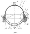
- FIG.1 is a general appearance of the tank for the liquid storage and expulsion presented as its longitudinal cross-section.
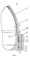
- FIG.2 is the detail I of FIG.1 in the enlarged scale.
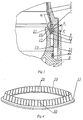
- FIG.3 is a tank attachment point with the diaphragm mounting during the assembling.
- FIG.4 is a thin-walled ring.
- a tank for the liquid storage and expulsion comprises a structural envelope 1 made in a form of hemisphere, and a tube flange 2 integrated by its end with the end of structural envelope 1.
- the tube flange 2 is located along the longitudinal axis of the said hemisphere of the structural envelope 1, and a ring groove 3 is made in its internal surface.
- the connection 4 for filling and discharging the liquid is mounted in the structural envelope 1.
- the tightening ring 5 is located coaxially with the longitudinal axis of the structural envelope 1.
- the elastic diaphragm 6 is fastened between the tube flange 2 and the tightening ring 5 and is made in a form of hemisphere integrated by its end with the cylinder provided with an end projection 7 on the external surface of its base, that fits into the ring groove 3 of the tube flange 2.
- the external surface of the tightening ring 5 and internal surface of the tube flange 2 are made in a form of a cylinder in the place of the end projection 7 location in the ring groove 3.
- the device has a bottom 8 made in a form of a part of a sphere providing a possibility for its end influence upon the end of the tightening ring 5 and leak-proof connection of the structural envelope 1 to the tube flange 2.
- Connection 9 for the control gas feed is mounted in the bottom 8.
- a thin-walled ring 10 is introduced into the design (FIG. 1, 2, 3, 4), that is provided with a shoulder 11 (FIG. 2, 3, 4), and that is mounted between the tightening ring 5 and an elastic diaphragm 6 in the place of location of its ring projection 7.
- the tube flange 2 is provided with a ring projection 12 (FIG.3), located on the internal surface of the tube flange 2 from the side of the bottom 8 ahead of the ring groove 3. From the side of the bottom 8 the tightening ring 5 is made with the lateral flange 13 (FIG.3) to tighten the shoulder 11 of the thin-walled ring 10 to the ring projection 12 of the tube flange 2 by it.
- the bottom 8 (FIG.1) is made hollow with a space 14, and its internal surface has holes 15.
- a splitter 16 is introduced into the space 14 of the bottom 8 in the place of location of the connection 9 for the control gas feed.
- a thin-walled ring 10 (FIG.4) is made with longitudinal cuttings 19 in its wall to form elastic tabs 20 out of the wall.
- a thin-walled ring 10 fits into the cylinder turning in the structural envelope 1 and is loaded by the tightening ring 5 (FIG. 1, 2, 3).
- the angle of slope of the thin-walled ring 10 tapered surface generatrix to the longitudinal axis of the structural envelope 1 being equal to the angle of slope a of the tightening ring 5 tapered part generatrix.
- the required elastic deformation of elastic tabs 20 (FIG.4) is reached by this and by the proper selection of material for the thin-walled ring 10.
- the splitter 16 (FIG.1) may be made in a form of a plate with perforated holes 21 the edges of which are fastened to the internal surface of the bottom 8 inside the space 14 connected to the connection 9 for the control gas feed.
- the splitter 16 with holes 21 is used for securing the uniform effect of the gas flow upon the elastic diaphragm 6.
- Other design members may be used also for splitting the control gas flow.
- the internal surface of the tightening ring 5 may be made to have a curvature radius R (FIG.1) and integrated with the internal surface of the bottom 8 providing a possibility for complementing a part of the sphere of the bottom 8 internal surface together with the internal surface of the tightening ring 5 up to a hemisphere.
- a gasket 22 (FIG. 1, 2, 3) may be used in the design for raising the quality of joints. From the side of the bottom 8 it is mounted ahead of the ring groove 3 between the internal surface of the tube flange 2 and external surface of the bottom 8 being in contact with the tube flange 2.
- the bottom 8 may be connected to the structural envelope 1 by different means.
- a coupling nut 23 may be used for connecting the bottom 8 and a tube flange 2 of the structural envelope 1 by a threaded connection of the said flange 2 and a coupling nut 23.
- the said threaded connection may be additionally sealed by a weld.
- FIG.3 shows the assembly sequence for the tank designed for the liquid storage and expulsion.
- the elastic diaphragm 6 is installed into the structural envelope 1 in such a way that the end projection 7 fits into the ring groove 3.
- the thin-walled ring 10 and the tightening ring 5 are mounted after that.
- the tightening ring 5 is inserted into the structural envelope 1 until the shoulder 11 of the thin-walled ring 10 fits on the ring projection 12 of the tube flange 2 (FIG.3).
- the use of the thin-walled ring 10 allows to rule out the axial force F (FIG.3) during the assembling, that seeks to pull the end projection 7 of the elastic diaphragm 6 out of the ring groove 3, and to distribute it in such a way that its effect on the end projection 7 in the axial direction is excluded substantially completely.
- a radial force F 1 is created as a result of this that occurs at the moment of contact of the tightening ring 5 and the thin-walled ring 10 and influences upon the end projection 7 of the elastic diaphragm 6.
- the elastic tabs 20 of the thin-walled ring 10 are radially deformed gradually as the tightening ring 5 moves during the assembling.
- the end projection 7 of the elastic diaphragm 6 goes into the ring groove 3 of the tube flange 2 securing the guaranteed sealing of the elastic diaphragm 6 relative to the structural envelope 1.
- the presence of elastic tabs 20 decreases the force of the tightening ring 5 friction against the end projection 7 of the elastic diaphragm 6 and increases the reliability of the structure as a whole, that is especially important under the operation conditions of the elastic diaphragm 6 at multiple displacements under the conditions of high environmental pressure of up to 250 kgf/cm 2 .
- the device operates in the following way.
- the tank is filled with the liquid through the connection 4, the elastic diaphragm 6 being displaced on the bottom 8.
- the control gas is fed through the connection 9 after that, by the action of which the diaphragm 6 is returned into the initial position expulsing the liquid through the connection 4.
- the proposed design of the elastic diaphragm end part attachment point secures the leak-proofness at high pressure and multiple (over 450) displacements and provides an opportunity for the elastic envelope reverse bend substantially without its tension.
- the propellant tank is designed for the liquid storage and expulsion, for the starting fuel of liquid-propellant rocket engines mainly.
- the invention may be used in the fields of engineering requiring the liquid media storage and expulsion into the corresponding hydraulic lines, in the gas and oil industry for example.
Landscapes
- Engineering & Computer Science (AREA)
- Physics & Mathematics (AREA)
- Fluid Mechanics (AREA)
- Mechanical Engineering (AREA)
- General Engineering & Computer Science (AREA)
- Filling Or Discharging Of Gas Storage Vessels (AREA)
- Supply Devices, Intensifiers, Converters, And Telemotors (AREA)
- Details Of Rigid Or Semi-Rigid Containers (AREA)
Applications Claiming Priority (2)
| Application Number | Priority Date | Filing Date | Title |
|---|---|---|---|
| RU99103516 | 1999-02-23 | ||
| RU99103516/28A RU2158699C1 (ru) | 1999-02-23 | 1999-02-23 | Бак для хранения и вытеснения жидкости |
Publications (3)
| Publication Number | Publication Date |
|---|---|
| EP1031729A2 true EP1031729A2 (de) | 2000-08-30 |
| EP1031729A3 EP1031729A3 (de) | 2003-05-07 |
| EP1031729B1 EP1031729B1 (de) | 2008-02-27 |
Family
ID=20216230
Family Applications (1)
| Application Number | Title | Priority Date | Filing Date |
|---|---|---|---|
| EP99117880A Expired - Lifetime EP1031729B1 (de) | 1999-02-23 | 1999-09-10 | Tank für die Speicherung und Austreibung einer Flüssigkeit |
Country Status (4)
| Country | Link |
|---|---|
| US (1) | US6129236A (de) |
| EP (1) | EP1031729B1 (de) |
| DE (1) | DE69938226T2 (de) |
| RU (1) | RU2158699C1 (de) |
Cited By (5)
| Publication number | Priority date | Publication date | Assignee | Title |
|---|---|---|---|---|
| WO2002079653A1 (de) * | 2001-03-31 | 2002-10-10 | Hydac Technology Gmbh | Hydropneumatischer druckspeicher |
| EP2447544A2 (de) | 2010-10-29 | 2012-05-02 | MT Aerospace AG | Behälter zum Aufnehmen, Speichern und Abgeben von gasförmigen, flüssigen und festen Medien sowie dessen Verwendung |
| DE102011117489A1 (de) * | 2011-10-27 | 2013-05-02 | Astrium Gmbh | Treibstofftank |
| WO2020018565A1 (en) * | 2018-07-16 | 2020-01-23 | Moog Inc. | Three-dimensional monolithic diaphragm tank |
| CN115673691A (zh) * | 2022-11-16 | 2023-02-03 | 兰州空间技术物理研究所 | 一种推进剂贮箱法兰外形及安装孔精度安装保证方法 |
Families Citing this family (20)
| Publication number | Priority date | Publication date | Assignee | Title |
|---|---|---|---|---|
| DE19615422A1 (de) | 1996-04-19 | 1997-11-20 | Boehringer Ingelheim Kg | Zweikammer-Kartusche für treibgasfreie Dosieraerosole |
| US6685691B1 (en) | 1998-02-27 | 2004-02-03 | Boehringer Ingelheim Gmbh | Container for a medicinal liquid |
| US7963955B2 (en) * | 1998-02-27 | 2011-06-21 | Boehringer Ingelheim International Gmbh | Container for a medicinal liquid |
| DE19851404A1 (de) * | 1998-11-07 | 2000-05-11 | Boehringer Ingelheim Int | Druckausgleichsvorrichtung für einen Doppelbehälter |
| DE19940713A1 (de) | 1999-02-23 | 2001-03-01 | Boehringer Ingelheim Int | Kartusche für eine Flüssigkeit |
| US6199717B1 (en) * | 2000-06-09 | 2001-03-13 | Fu-Jen Tsai | Container for storing and supplying water under pressure |
| US6786364B2 (en) * | 2001-08-08 | 2004-09-07 | Mcbride Dale | Transportable storage with an autonomous dispensing system |
| US6726052B1 (en) * | 2003-03-19 | 2004-04-27 | The United States Of America As Represented By The Secretary Of The Army | Collapsible fluid transport tank |
| DE10340292A1 (de) * | 2003-09-02 | 2005-04-14 | Mahle Gmbh | Kolben für einen Verbrennungsmotor |
| DE102005029746B4 (de) * | 2005-06-24 | 2017-10-26 | Boehringer Ingelheim International Gmbh | Zerstäuber |
| US8079126B2 (en) * | 2008-01-25 | 2011-12-20 | Pratt & Whitney Rocketdyne, Inc. | Friction stir welded bladder fuel tank |
| DE102008014773A1 (de) * | 2008-03-18 | 2009-10-08 | Delo Industrieklebstoffe Gmbh & Co. Kg | Behälter für fließfähige Substanzen |
| EP2182294B1 (de) * | 2008-10-28 | 2017-03-01 | Reflex Winkelmann GmbH | Druckausdehnungsgefäß |
| ITGE20130010A1 (it) * | 2013-01-24 | 2014-07-25 | Enosis Srl | Dispositivo per la protezione di un liquido dall'ossidazione |
| WO2015048179A1 (en) | 2013-09-24 | 2015-04-02 | Pentair Residential Filtration, Llc | Pressure vessel system and method |
| KR20150046644A (ko) * | 2013-10-22 | 2015-04-30 | 삼성전자주식회사 | 나노 임프린트용 레진 디스펜서 |
| IT201600108035A1 (it) * | 2016-10-26 | 2018-04-26 | Hutchinson Srl | Smorzatore per una linea di fluido, in particolare una linea del carburante per un motore a combustione interna |
| CN110219750A (zh) * | 2019-05-28 | 2019-09-10 | 西安航天动力研究所 | 一种高可靠高压起动箱 |
| CN112284658B (zh) * | 2020-09-17 | 2023-02-14 | 沈阳航天新光集团有限公司 | 增强非金属隔膜贮箱抗振能力的方法及试验方法 |
| US12013131B2 (en) * | 2022-07-29 | 2024-06-18 | Dab Pumps S.P.A. | Expansion vessel with membrane, pump comprising the expansion vessel and relative manufacturing method |
Citations (2)
| Publication number | Priority date | Publication date | Assignee | Title |
|---|---|---|---|---|
| US4117866A (en) | 1973-11-13 | 1978-10-03 | Gerhard Bohm | Hollow body and method of making the same |
| US4335751A (en) | 1979-08-15 | 1982-06-22 | Kazuo Sugimura | Accumulator |
Family Cites Families (12)
| Publication number | Priority date | Publication date | Assignee | Title |
|---|---|---|---|---|
| DE877517C (de) * | 1945-08-21 | 1953-05-26 | Jean Mercier | Druckakkumulator |
| US2880759A (en) * | 1956-06-06 | 1959-04-07 | Bendix Aviat Corp | Hydro-pneumatic energy storage device |
| US3222498A (en) * | 1962-05-11 | 1965-12-07 | American Radiator & Standard | Vapor generator |
| DE1525476A1 (de) * | 1966-03-01 | 1969-07-10 | Langen & Co | Hydro-pneumatischer Druckspeicher |
| US3750367A (en) * | 1972-03-28 | 1973-08-07 | Mead Corp | Web sterilizing system |
| DE2817011A1 (de) * | 1978-04-19 | 1979-10-25 | Bosch Gmbh Robert | Druckbehaelter |
| US4364416A (en) * | 1981-09-25 | 1982-12-21 | Vsi Corporation | Low cost accumulator device |
| US4763805A (en) * | 1984-11-20 | 1988-08-16 | Amoco Corporation | Underground tank assembly with internal bladder |
| US4817830A (en) * | 1986-10-31 | 1989-04-04 | Ecodyne Corporation | Pressure vessel with a bladder |
| US5176178A (en) * | 1991-02-20 | 1993-01-05 | Aos Holding Company | Accumulator with randomly uniplanar bladder collapse |
| DE4121857A1 (de) * | 1991-07-02 | 1993-01-07 | Ladoco Ag | Druckbehaelter fuer gase, fluessigkeiten, pastoese produkte oder dergleichen |
| US5427152A (en) * | 1991-09-21 | 1995-06-27 | Hydac Technology Gmbh | Hydraulic accumulator with dividing wall supported by connecting and retaining parts |
-
1999
- 1999-02-23 RU RU99103516/28A patent/RU2158699C1/ru not_active IP Right Cessation
- 1999-09-02 US US09/388,798 patent/US6129236A/en not_active Expired - Lifetime
- 1999-09-10 DE DE69938226T patent/DE69938226T2/de not_active Expired - Lifetime
- 1999-09-10 EP EP99117880A patent/EP1031729B1/de not_active Expired - Lifetime
Patent Citations (2)
| Publication number | Priority date | Publication date | Assignee | Title |
|---|---|---|---|---|
| US4117866A (en) | 1973-11-13 | 1978-10-03 | Gerhard Bohm | Hollow body and method of making the same |
| US4335751A (en) | 1979-08-15 | 1982-06-22 | Kazuo Sugimura | Accumulator |
Cited By (15)
| Publication number | Priority date | Publication date | Assignee | Title |
|---|---|---|---|---|
| WO2002079653A1 (de) * | 2001-03-31 | 2002-10-10 | Hydac Technology Gmbh | Hydropneumatischer druckspeicher |
| DE10116235A1 (de) * | 2001-03-31 | 2002-10-17 | Hydac Technology Gmbh | Hydropneumatischer Druckspeicher |
| US6857450B2 (en) | 2001-03-31 | 2005-02-22 | Hydac Technology Gmbh | Hydropneumatic pressure reservoir |
| EP1517048A2 (de) | 2001-03-31 | 2005-03-23 | HYDAC Technology GmbH | Hydropneumatischer Druckspeicher |
| EP1517048A3 (de) * | 2001-03-31 | 2005-11-09 | HYDAC Technology GmbH | Hydropneumatischer Druckspeicher |
| DE102010050113A1 (de) | 2010-10-29 | 2012-05-31 | Mt Aerospace Ag | Behälter zum Aufnehmen, Speichern und Abgeben von gasförmigen, flüssigen und festen Medien sowie dessen Verwendung |
| EP2447544A2 (de) | 2010-10-29 | 2012-05-02 | MT Aerospace AG | Behälter zum Aufnehmen, Speichern und Abgeben von gasförmigen, flüssigen und festen Medien sowie dessen Verwendung |
| DE102011117489A1 (de) * | 2011-10-27 | 2013-05-02 | Astrium Gmbh | Treibstofftank |
| EP2636602A1 (de) * | 2011-10-27 | 2013-09-11 | Astrium GmbH | Treibstofftank |
| DE102011117489B4 (de) * | 2011-10-27 | 2015-04-02 | Astrium Gmbh | Treibstofftank |
| US9052062B2 (en) | 2011-10-27 | 2015-06-09 | Astrium Gmbh | Fuel tank with separating membrane |
| WO2020018565A1 (en) * | 2018-07-16 | 2020-01-23 | Moog Inc. | Three-dimensional monolithic diaphragm tank |
| US11067037B2 (en) | 2018-07-16 | 2021-07-20 | Moog Inc. | Three-dimensional monolithic diaphragm tank |
| US11920542B2 (en) | 2018-07-16 | 2024-03-05 | Moog Inc. | Three-dimensional monolithic diaphragm tank |
| CN115673691A (zh) * | 2022-11-16 | 2023-02-03 | 兰州空间技术物理研究所 | 一种推进剂贮箱法兰外形及安装孔精度安装保证方法 |
Also Published As
| Publication number | Publication date |
|---|---|
| DE69938226D1 (de) | 2008-04-10 |
| RU2158699C1 (ru) | 2000-11-10 |
| EP1031729A3 (de) | 2003-05-07 |
| US6129236A (en) | 2000-10-10 |
| DE69938226T2 (de) | 2009-03-26 |
| EP1031729B1 (de) | 2008-02-27 |
Similar Documents
| Publication | Publication Date | Title |
|---|---|---|
| EP1031729B1 (de) | Tank für die Speicherung und Austreibung einer Flüssigkeit | |
| US3984132A (en) | Bulkhead fitting | |
| EP1818592B1 (de) | Verbindungsstruktur für einen kunststoffschlauch | |
| US4213619A (en) | Sealing insert for the tight connection of two pipes | |
| KR100251258B1 (ko) | 고압 금속 배관의 접속 헤드 및 그 고압 배관이 접속되는 공통 레일 | |
| KR940003795A (ko) | 액체 용기용 튜브 | |
| SE468527B (sv) | Grenroerskoppling till ett huvudroer foer braensle under hoegt tryck | |
| US4401325A (en) | Flexible pipe coupling | |
| EP3346178A1 (de) | Hochdruck behälter | |
| SE518314C2 (sv) | Bränslefördelningsrör | |
| US10697590B2 (en) | High pressure tank | |
| US5407092A (en) | Profiled thickness bonded rolling diaphragm tank | |
| GB1592306A (en) | Hydraulic control cylinders | |
| US4598937A (en) | Pipe having a double flared end | |
| US6749184B2 (en) | Air spring and method for making the same | |
| US4460050A (en) | Pipe driving attachment | |
| US4033593A (en) | Seal for large annular openings | |
| US20230383768A1 (en) | Diaphragm for a Fluid Storage Tank | |
| US4351363A (en) | Hydro-pneumatic pressure vessel | |
| US4148495A (en) | Sealing means for a membrane filtration unit | |
| GB2064652A (en) | Pressure vessels | |
| US3940032A (en) | Rolling diaphragms for expelling liquids | |
| US4201246A (en) | Pressure accumulator | |
| US4705546A (en) | Fuel collection in surface tension fuel tanks | |
| JP3762467B2 (ja) | 細径金属管と可撓ホースとの接続構造 |
Legal Events
| Date | Code | Title | Description |
|---|---|---|---|
| PUAI | Public reference made under article 153(3) epc to a published international application that has entered the european phase |
Free format text: ORIGINAL CODE: 0009012 |
|
| AK | Designated contracting states |
Kind code of ref document: A2 Designated state(s): AT BE CH CY DE DK ES FI FR GB GR IE IT LI LU MC NL PT SE |
|
| AX | Request for extension of the european patent |
Free format text: AL;LT;LV;MK;RO;SI |
|
| PUAL | Search report despatched |
Free format text: ORIGINAL CODE: 0009013 |
|
| AK | Designated contracting states |
Designated state(s): AT BE CH CY DE DK ES FI FR GB GR IE IT LI LU MC NL PT SE |
|
| AX | Request for extension of the european patent |
Extension state: AL LT LV MK RO SI |
|
| RIC1 | Information provided on ipc code assigned before grant |
Ipc: 7F 02K 9/50 B Ipc: 7F 15B 1/18 B Ipc: 7F 15B 1/14 A |
|
| 17P | Request for examination filed |
Effective date: 20031107 |
|
| AKX | Designation fees paid |
Designated state(s): DE FR GB IT SE |
|
| RAP1 | Party data changed (applicant data changed or rights of an application transferred) |
Owner name: OTKRYTOE AKTSIONERNOE OBSCHESTVO NAUCHNO-PROIZVODS |
|
| 17Q | First examination report despatched |
Effective date: 20040820 |
|
| RAP1 | Party data changed (applicant data changed or rights of an application transferred) |
Owner name: OTKRYTOE AKTSIONERNOE OBSCHESTVO "NPO ENERGOMASH |
|
| GRAP | Despatch of communication of intention to grant a patent |
Free format text: ORIGINAL CODE: EPIDOSNIGR1 |
|
| GRAS | Grant fee paid |
Free format text: ORIGINAL CODE: EPIDOSNIGR3 |
|
| GRAA | (expected) grant |
Free format text: ORIGINAL CODE: 0009210 |
|
| AK | Designated contracting states |
Kind code of ref document: B1 Designated state(s): DE FR GB IT SE |
|
| REG | Reference to a national code |
Ref country code: GB Ref legal event code: FG4D |
|
| REF | Corresponds to: |
Ref document number: 69938226 Country of ref document: DE Date of ref document: 20080410 Kind code of ref document: P |
|
| REG | Reference to a national code |
Ref country code: SE Ref legal event code: TRGR |
|
| ET | Fr: translation filed | ||
| PLBE | No opposition filed within time limit |
Free format text: ORIGINAL CODE: 0009261 |
|
| STAA | Information on the status of an ep patent application or granted ep patent |
Free format text: STATUS: NO OPPOSITION FILED WITHIN TIME LIMIT |
|
| 26N | No opposition filed |
Effective date: 20081128 |
|
| REG | Reference to a national code |
Ref country code: FR Ref legal event code: PLFP Year of fee payment: 17 |
|
| REG | Reference to a national code |
Ref country code: FR Ref legal event code: PLFP Year of fee payment: 18 |
|
| REG | Reference to a national code |
Ref country code: FR Ref legal event code: PLFP Year of fee payment: 19 |
|
| PGFP | Annual fee paid to national office [announced via postgrant information from national office to epo] |
Ref country code: IT Payment date: 20170922 Year of fee payment: 19 Ref country code: GB Payment date: 20170929 Year of fee payment: 19 |
|
| PGFP | Annual fee paid to national office [announced via postgrant information from national office to epo] |
Ref country code: SE Payment date: 20170926 Year of fee payment: 19 |
|
| PGFP | Annual fee paid to national office [announced via postgrant information from national office to epo] |
Ref country code: FR Payment date: 20171002 Year of fee payment: 19 Ref country code: DE Payment date: 20171130 Year of fee payment: 19 |
|
| REG | Reference to a national code |
Ref country code: DE Ref legal event code: R119 Ref document number: 69938226 Country of ref document: DE |
|
| REG | Reference to a national code |
Ref country code: SE Ref legal event code: EUG |
|
| GBPC | Gb: european patent ceased through non-payment of renewal fee |
Effective date: 20180910 |
|
| PG25 | Lapsed in a contracting state [announced via postgrant information from national office to epo] |
Ref country code: SE Free format text: LAPSE BECAUSE OF NON-PAYMENT OF DUE FEES Effective date: 20180911 |
|
| PG25 | Lapsed in a contracting state [announced via postgrant information from national office to epo] |
Ref country code: DE Free format text: LAPSE BECAUSE OF NON-PAYMENT OF DUE FEES Effective date: 20190402 Ref country code: IT Free format text: LAPSE BECAUSE OF NON-PAYMENT OF DUE FEES Effective date: 20180910 |
|
| PG25 | Lapsed in a contracting state [announced via postgrant information from national office to epo] |
Ref country code: FR Free format text: LAPSE BECAUSE OF NON-PAYMENT OF DUE FEES Effective date: 20180930 |
|
| PG25 | Lapsed in a contracting state [announced via postgrant information from national office to epo] |
Ref country code: GB Free format text: LAPSE BECAUSE OF NON-PAYMENT OF DUE FEES Effective date: 20180910 |