US10697590B2 - High pressure tank - Google Patents
High pressure tank Download PDFInfo
- Publication number
- US10697590B2 US10697590B2 US15/920,581 US201815920581A US10697590B2 US 10697590 B2 US10697590 B2 US 10697590B2 US 201815920581 A US201815920581 A US 201815920581A US 10697590 B2 US10697590 B2 US 10697590B2
- Authority
- US
- United States
- Prior art keywords
- cap
- liner
- opening
- passage
- gas vent
- Prior art date
- Legal status (The legal status is an assumption and is not a legal conclusion. Google has not performed a legal analysis and makes no representation as to the accuracy of the status listed.)
- Active, expires
Links
- 239000012530 fluid Substances 0.000 claims abstract description 41
- 239000011347 resin Substances 0.000 claims abstract description 24
- 229920005989 resin Polymers 0.000 claims abstract description 24
- 239000000463 material Substances 0.000 claims description 23
- 238000003780 insertion Methods 0.000 claims description 19
- 230000037431 insertion Effects 0.000 claims description 19
- 230000000149 penetrating effect Effects 0.000 claims description 4
- 238000007599 discharging Methods 0.000 abstract 1
- 239000007789 gas Substances 0.000 description 50
- 230000035882 stress Effects 0.000 description 42
- UFHFLCQGNIYNRP-UHFFFAOYSA-N Hydrogen Chemical compound [H][H] UFHFLCQGNIYNRP-UHFFFAOYSA-N 0.000 description 33
- 239000000446 fuel Substances 0.000 description 6
- 239000012466 permeate Substances 0.000 description 6
- 230000000717 retained effect Effects 0.000 description 5
- 230000000694 effects Effects 0.000 description 3
- 229910052751 metal Inorganic materials 0.000 description 3
- 239000002184 metal Substances 0.000 description 3
- 230000008646 thermal stress Effects 0.000 description 3
- 229920002430 Fibre-reinforced plastic Polymers 0.000 description 2
- 230000008901 benefit Effects 0.000 description 2
- 239000011151 fibre-reinforced plastic Substances 0.000 description 2
- 230000014759 maintenance of location Effects 0.000 description 2
- 230000004048 modification Effects 0.000 description 2
- 238000012986 modification Methods 0.000 description 2
- 229910052782 aluminium Inorganic materials 0.000 description 1
- XAGFODPZIPBFFR-UHFFFAOYSA-N aluminium Chemical compound [Al] XAGFODPZIPBFFR-UHFFFAOYSA-N 0.000 description 1
- 230000003247 decreasing effect Effects 0.000 description 1
- 239000001257 hydrogen Substances 0.000 description 1
- 229910052739 hydrogen Inorganic materials 0.000 description 1
- 239000007788 liquid Substances 0.000 description 1
- 230000002093 peripheral effect Effects 0.000 description 1
- 238000011144 upstream manufacturing Methods 0.000 description 1
Images


Classifications
-
- F—MECHANICAL ENGINEERING; LIGHTING; HEATING; WEAPONS; BLASTING
- F16—ENGINEERING ELEMENTS AND UNITS; GENERAL MEASURES FOR PRODUCING AND MAINTAINING EFFECTIVE FUNCTIONING OF MACHINES OR INSTALLATIONS; THERMAL INSULATION IN GENERAL
- F16J—PISTONS; CYLINDERS; SEALINGS
- F16J12/00—Pressure vessels in general
-
- F—MECHANICAL ENGINEERING; LIGHTING; HEATING; WEAPONS; BLASTING
- F17—STORING OR DISTRIBUTING GASES OR LIQUIDS
- F17C—VESSELS FOR CONTAINING OR STORING COMPRESSED, LIQUEFIED OR SOLIDIFIED GASES; FIXED-CAPACITY GAS-HOLDERS; FILLING VESSELS WITH, OR DISCHARGING FROM VESSELS, COMPRESSED, LIQUEFIED, OR SOLIDIFIED GASES
- F17C1/00—Pressure vessels, e.g. gas cylinder, gas tank, replaceable cartridge
- F17C1/16—Pressure vessels, e.g. gas cylinder, gas tank, replaceable cartridge constructed of plastics materials
-
- F—MECHANICAL ENGINEERING; LIGHTING; HEATING; WEAPONS; BLASTING
- F17—STORING OR DISTRIBUTING GASES OR LIQUIDS
- F17C—VESSELS FOR CONTAINING OR STORING COMPRESSED, LIQUEFIED OR SOLIDIFIED GASES; FIXED-CAPACITY GAS-HOLDERS; FILLING VESSELS WITH, OR DISCHARGING FROM VESSELS, COMPRESSED, LIQUEFIED, OR SOLIDIFIED GASES
- F17C13/00—Details of vessels or of the filling or discharging of vessels
- F17C13/06—Closures, e.g. cap, breakable member
-
- F—MECHANICAL ENGINEERING; LIGHTING; HEATING; WEAPONS; BLASTING
- F17—STORING OR DISTRIBUTING GASES OR LIQUIDS
- F17C—VESSELS FOR CONTAINING OR STORING COMPRESSED, LIQUEFIED OR SOLIDIFIED GASES; FIXED-CAPACITY GAS-HOLDERS; FILLING VESSELS WITH, OR DISCHARGING FROM VESSELS, COMPRESSED, LIQUEFIED, OR SOLIDIFIED GASES
- F17C1/00—Pressure vessels, e.g. gas cylinder, gas tank, replaceable cartridge
- F17C1/02—Pressure vessels, e.g. gas cylinder, gas tank, replaceable cartridge involving reinforcing arrangements
-
- F—MECHANICAL ENGINEERING; LIGHTING; HEATING; WEAPONS; BLASTING
- F17—STORING OR DISTRIBUTING GASES OR LIQUIDS
- F17C—VESSELS FOR CONTAINING OR STORING COMPRESSED, LIQUEFIED OR SOLIDIFIED GASES; FIXED-CAPACITY GAS-HOLDERS; FILLING VESSELS WITH, OR DISCHARGING FROM VESSELS, COMPRESSED, LIQUEFIED, OR SOLIDIFIED GASES
- F17C2201/00—Vessel construction, in particular geometry, arrangement or size
- F17C2201/01—Shape
- F17C2201/0104—Shape cylindrical
- F17C2201/0109—Shape cylindrical with exteriorly curved end-piece
-
- F—MECHANICAL ENGINEERING; LIGHTING; HEATING; WEAPONS; BLASTING
- F17—STORING OR DISTRIBUTING GASES OR LIQUIDS
- F17C—VESSELS FOR CONTAINING OR STORING COMPRESSED, LIQUEFIED OR SOLIDIFIED GASES; FIXED-CAPACITY GAS-HOLDERS; FILLING VESSELS WITH, OR DISCHARGING FROM VESSELS, COMPRESSED, LIQUEFIED, OR SOLIDIFIED GASES
- F17C2203/00—Vessel construction, in particular walls or details thereof
- F17C2203/01—Reinforcing or suspension means
- F17C2203/011—Reinforcing means
- F17C2203/012—Reinforcing means on or in the wall, e.g. ribs
-
- F—MECHANICAL ENGINEERING; LIGHTING; HEATING; WEAPONS; BLASTING
- F17—STORING OR DISTRIBUTING GASES OR LIQUIDS
- F17C—VESSELS FOR CONTAINING OR STORING COMPRESSED, LIQUEFIED OR SOLIDIFIED GASES; FIXED-CAPACITY GAS-HOLDERS; FILLING VESSELS WITH, OR DISCHARGING FROM VESSELS, COMPRESSED, LIQUEFIED, OR SOLIDIFIED GASES
- F17C2203/00—Vessel construction, in particular walls or details thereof
- F17C2203/06—Materials for walls or layers thereof; Properties or structures of walls or their materials
- F17C2203/0602—Wall structures; Special features thereof
- F17C2203/0604—Liners
-
- F—MECHANICAL ENGINEERING; LIGHTING; HEATING; WEAPONS; BLASTING
- F17—STORING OR DISTRIBUTING GASES OR LIQUIDS
- F17C—VESSELS FOR CONTAINING OR STORING COMPRESSED, LIQUEFIED OR SOLIDIFIED GASES; FIXED-CAPACITY GAS-HOLDERS; FILLING VESSELS WITH, OR DISCHARGING FROM VESSELS, COMPRESSED, LIQUEFIED, OR SOLIDIFIED GASES
- F17C2203/00—Vessel construction, in particular walls or details thereof
- F17C2203/06—Materials for walls or layers thereof; Properties or structures of walls or their materials
- F17C2203/0602—Wall structures; Special features thereof
- F17C2203/0612—Wall structures
- F17C2203/0614—Single wall
- F17C2203/0619—Single wall with two layers
-
- F—MECHANICAL ENGINEERING; LIGHTING; HEATING; WEAPONS; BLASTING
- F17—STORING OR DISTRIBUTING GASES OR LIQUIDS
- F17C—VESSELS FOR CONTAINING OR STORING COMPRESSED, LIQUEFIED OR SOLIDIFIED GASES; FIXED-CAPACITY GAS-HOLDERS; FILLING VESSELS WITH, OR DISCHARGING FROM VESSELS, COMPRESSED, LIQUEFIED, OR SOLIDIFIED GASES
- F17C2203/00—Vessel construction, in particular walls or details thereof
- F17C2203/06—Materials for walls or layers thereof; Properties or structures of walls or their materials
- F17C2203/0634—Materials for walls or layers thereof
- F17C2203/0658—Synthetics
- F17C2203/0663—Synthetics in form of fibers or filaments
-
- F—MECHANICAL ENGINEERING; LIGHTING; HEATING; WEAPONS; BLASTING
- F17—STORING OR DISTRIBUTING GASES OR LIQUIDS
- F17C—VESSELS FOR CONTAINING OR STORING COMPRESSED, LIQUEFIED OR SOLIDIFIED GASES; FIXED-CAPACITY GAS-HOLDERS; FILLING VESSELS WITH, OR DISCHARGING FROM VESSELS, COMPRESSED, LIQUEFIED, OR SOLIDIFIED GASES
- F17C2205/00—Vessel construction, in particular mounting arrangements, attachments or identifications means
- F17C2205/03—Fluid connections, filters, valves, closure means or other attachments
- F17C2205/0302—Fittings, valves, filters, or components in connection with the gas storage device
- F17C2205/0305—Bosses, e.g. boss collars
-
- F—MECHANICAL ENGINEERING; LIGHTING; HEATING; WEAPONS; BLASTING
- F17—STORING OR DISTRIBUTING GASES OR LIQUIDS
- F17C—VESSELS FOR CONTAINING OR STORING COMPRESSED, LIQUEFIED OR SOLIDIFIED GASES; FIXED-CAPACITY GAS-HOLDERS; FILLING VESSELS WITH, OR DISCHARGING FROM VESSELS, COMPRESSED, LIQUEFIED, OR SOLIDIFIED GASES
- F17C2209/00—Vessel construction, in particular methods of manufacturing
- F17C2209/23—Manufacturing of particular parts or at special locations
- F17C2209/234—Manufacturing of particular parts or at special locations of closing end pieces, e.g. caps
-
- F—MECHANICAL ENGINEERING; LIGHTING; HEATING; WEAPONS; BLASTING
- F17—STORING OR DISTRIBUTING GASES OR LIQUIDS
- F17C—VESSELS FOR CONTAINING OR STORING COMPRESSED, LIQUEFIED OR SOLIDIFIED GASES; FIXED-CAPACITY GAS-HOLDERS; FILLING VESSELS WITH, OR DISCHARGING FROM VESSELS, COMPRESSED, LIQUEFIED, OR SOLIDIFIED GASES
- F17C2221/00—Handled fluid, in particular type of fluid
- F17C2221/01—Pure fluids
- F17C2221/012—Hydrogen
-
- F—MECHANICAL ENGINEERING; LIGHTING; HEATING; WEAPONS; BLASTING
- F17—STORING OR DISTRIBUTING GASES OR LIQUIDS
- F17C—VESSELS FOR CONTAINING OR STORING COMPRESSED, LIQUEFIED OR SOLIDIFIED GASES; FIXED-CAPACITY GAS-HOLDERS; FILLING VESSELS WITH, OR DISCHARGING FROM VESSELS, COMPRESSED, LIQUEFIED, OR SOLIDIFIED GASES
- F17C2270/00—Applications
- F17C2270/01—Applications for fluid transport or storage
- F17C2270/0165—Applications for fluid transport or storage on the road
- F17C2270/0184—Fuel cells
-
- Y—GENERAL TAGGING OF NEW TECHNOLOGICAL DEVELOPMENTS; GENERAL TAGGING OF CROSS-SECTIONAL TECHNOLOGIES SPANNING OVER SEVERAL SECTIONS OF THE IPC; TECHNICAL SUBJECTS COVERED BY FORMER USPC CROSS-REFERENCE ART COLLECTIONS [XRACs] AND DIGESTS
- Y02—TECHNOLOGIES OR APPLICATIONS FOR MITIGATION OR ADAPTATION AGAINST CLIMATE CHANGE
- Y02E—REDUCTION OF GREENHOUSE GAS [GHG] EMISSIONS, RELATED TO ENERGY GENERATION, TRANSMISSION OR DISTRIBUTION
- Y02E60/00—Enabling technologies; Technologies with a potential or indirect contribution to GHG emissions mitigation
- Y02E60/30—Hydrogen technology
- Y02E60/32—Hydrogen storage
-
- Y02E60/321—
Definitions
- the present invention relates to a high pressure tank that includes a liner that can contain a fluid inside and is made of resin, a reinforced layer that covers an outer surface of the liner, and a cap that includes a supply/discharge hole that is formed to supply and discharge the fluid to and from an interior of the liner.
- High pressure tanks are widely used as containers that contain fluids such as gases and liquids.
- a high pressure tank is mounted on a fuel cell vehicle as a container for a hydrogen gas to be supplied to a fuel cell system.
- a high pressure tank of this type is known to include a liner that can contain a fluid inside and is made of resin, a reinforced layer that covers an outer surface of the liner and is made of fiber-reinforced plastics, and a cap that includes a supply/discharge hole that is formed therein to supply and discharge a fluid to and from an interior of the liner.
- This supply/discharge hole is provided with, for example, a valve. By operating the valve, it is possible to supply the fluid to the interior of the liner and discharge the fluid contained inside the liner via the supply/discharge hole.
- a release path communicating the covered portion and an outside of the reinforced layer may be formed in a cap. That is, a first opening at one end of the release path is formed on a surface of the cap in contact with an outer surface of the liner (referred to as a contact surface below), and a second opening at the other end of the release path is formed on another surface of the cap facing outside the reinforced layer (referred to as an open surface below).
- the fluid at the covered portion is guided from the first opening into the release path, and the guided fluid is released outside the reinforced layer via the second opening. Therefore, a cross-sectional area perpendicular to a longitudinal direction of the release path (also simply referred to as a cross-sectional area below), and areas of the first opening and the second opening are set to sufficiently allow the fluid to pass therethrough.
- Japanese Laid-Open Patent Publication No. 11-210988 proposes making a cross-sectional area at one end of the release path and an area of the first opening larger than the other portion of the release path, and arranging a porous sheet that can allow a fluid to permeate at these enlarged cross-sectional portions. That is, the fluid is enabled to be guided to the release path via the porous sheet so that the fluid is prevented from retaining at the covered portion. Further, the porous sheet is arranged to be flush with the periphery of the first opening of a contact surface inside the enlarged portion, so that the contact surface is brought into contact with the outer surface of the liner along with the porous sheet, avoiding the above-mentioned stress concentration.
- the interior of the liner is highly pressurized at more than 100 MPa, for example.
- a significantly high load is applied to the porous sheet interposed between the outer surface of the liner and the cap. It is not easy to make the porous sheet that can withstand the load while keeping porosity.
- a temperature of the high pressure tank changes in a wide range from high to low.
- materials that constitute the porous sheet and the cap have different linear expansion coefficients, a thermal stress caused by the changes in temperature also needs to be considered.
- the porous sheet interposed at the enlarged cross-sectional portion of the release path it is difficult to design a high pressure tank that can prevent both the retention of the fluid at the covered portion and the above-mentioned stress concentration for a long period of time.
- a main object of the present invention is to provide a high pressure tank that can prevent a fluid from retaining between an outer surface of a liner and a reinforced layer, and effectively improve durability of the liner by a simple configuration.
- One embodiment of the present invention is a high pressure tank that includes: a resin liner configured to contain a fluid; a reinforced layer covering an outer surface of the liner; and a cap including a supply/discharge hole configured to supply and discharge the fluid to and from the liner, wherein the outer surface of the liner includes a reinforced-layer-facing surface facing toward the reinforced layer, and a cap-facing surface facing toward the cap; a gas vent passage is formed in the cap, and includes at one end a first opening facing toward the cap-facing surface and at the other end a second opening facing toward at least one of an inside of the supply/discharge hole and an outside of the reinforced layer; and a cross-sectional area of the gas vent passage at one end perpendicular to its longitudinal direction and an area of the first opening are smaller than a cross-sectional area of the gas vent passage at another portion perpendicular to the longitudinal direction.
- the cross-sectional area perpendicular to the longitudinal direction at the one end of the gas vent passage (also simply referred to as a cross-sectional area below), and the area of the first opening are smaller than the cross-sectional areas of the other portions of the gas vent passage.
- the cross-sectional area of the other portion of the gas vent passage is made lager than the area of the first opening to let the fluid flow through the gas vent passage smoothly. Consequently, it is possible to effectively guide the fluid between the reinforced layer and the reinforced-layer-facing surface into the supply/discharge hole or outside the reinforced layer. Consequently, it is possible to prevent buckling of the liner.
- this high pressure tank where the area of the first opening of the gas vent passage is made smaller than the cross-sectional area of the other portion can prevent the liner from suffering from stress concentration and creep, and the fluid from being retained between the outer surface of the liner and the reinforced layer. As a result, it is possible to effectively improve durability of the liner.
- the area of the first opening is preferably set such that a maximum shear stress generated at the portion of the liner facing toward the first opening is equal to or less than 1 ⁇ 2 of a yield stress S of the resin material constituting the liner.
- the yield stress S of the resin material described herein is a reference stress at which the resin material is plastically deformed, and basically refers to an elastic limit. However, the yield stress S may be 0.2% offset when it is difficult to measure the elastic limit.
- a diameter D of the first opening, a thickness T of the facing portion, and a maximum filling pressure P of the fluid and the yield stress S preferably satisfy a relationship of D ⁇ S ⁇ T ⁇ 2/P.
- the maximum shear stress ⁇ C can be equal to or less than 1 ⁇ 2 of the yield stress S of the resin material ( ⁇ C ⁇ 1 ⁇ 2S). Consequently, it is possible to more effectively prevent creep from being formed in the liner as described above.
- the high pressure tank may further include a plug inserted in an insertion hole formed in the cap to open toward the cap-facing surface, and at least part of a plug passage penetrating the plug may form the one end of the gas vent passage, and a cap passage formed in the cap may form the other end of the gas vent passage, and the first opening may be formed in an end surface of one end of the plug facing toward the cap-facing surface.
- the one end of the gas vent passage has the cross-sectional area that needs to be made smaller than the other portion of the gas vent passage, and therefore is difficult to be formed. Even such one end of the gas vent passage can be easily formed by using the plug. That is, the plug can be formed separately from the cap. Moreover, the plug only needs to have a shape that is insertable in the insertion hole of the cap, and therefore can be of an easy and simple shape. The plug passage can also be easily formed to penetrate through this plug. Consequently, it is possible to make the cross-sectional area of the entire plug passage small or form a portion of a small cross-sectional area at one end of the plug passage. By inserting the plug with the plug passage formed therein in the insertion hole that communicates with the cap passage, it is possible to easily form the gas vent passage formed by the cap passage and the plug passage.
- the high pressure tank may further include a plug inserted in an insertion hole formed in the cap to open toward the cap-facing surface, and at least part of a groove passage formed on a surface of the plug may form the one end of the gas vent passage, and a cap passage formed in the cap may form the other end of the gas vent passage, and the first opening may be formed in an end surface on one end of the plug facing toward the cap-facing surface.
- the groove passage can also be easily formed in the plug. Consequently, it is possible to easily form the gas vent passage having a small cross-sectional area on the one end.
- the plug is preferably made of the material same as the material of the cap.
- the cap and the plug can have the same linear expansion coefficient.
- FIG. 1 is a schematic cross-sectional view of a high pressure tank according to an embodiment of the present invention along an axial direction of a cylindrical portion of the high pressure tank;
- FIG. 2 is an enlarged cross-sectional view of a cap side of the high pressure tank shown in FIG. 1 ;
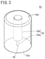
- FIG. 3 is a perspective view of a plug in FIG. 1 ;
- FIG. 4 is a view for explaining a shear stress generated at a portion of a liner
- FIG. 5 is a perspective view of the plug according to a modification.
- FIG. 6 is an enlarged cross-sectional view of the cap side of the high pressure tank according to another embodiment.
- the high pressure tank according to the present invention is mounted on, for example, a fuel cell vehicle, and is suitably used to contain a hydrogen gas to be supplied to a fuel cell system.
- the present embodiment will describe an example where the high pressure tank contains a hydrogen gas as a fluid to be supplied to the fuel cell system, yet is not limited to this in particular.
- the high pressure tank according to the present invention can contain fluid other than the hydrogen gas.
- a high pressure tank 10 mainly includes a reinforced layer 12 , a liner 14 and a cap 16 .
- the reinforced layer 12 is made of fiber-reinforced plastics, and covers an outer surface of the liner 14 .
- the liner 14 is a hollow body made of resin, and can contain a hydrogen gas inside. More specifically, the liner 14 includes a main body portion 18 having an outer surface covered by the reinforced layer 12 , a dented portion 20 that is bent inward of the main body portion 18 , and a cylindrical portion 22 that protrudes outward of the main body portion 18 from the dented portion 20 . That is, an outer surface of the main body portion 18 of the outer surface of the liner 14 is a reinforced-layer-facing surface 24 that faces toward the reinforced layer 12 . Outer surfaces of the dented portion 20 and the cylindrical portion 22 are a cap-facing surface 26 that faces toward the cap 16 as described below.
- a thin portion 22 a is formed on a protrusion end (distal end) side of the cylindrical portion 22 .
- a male screw 22 b is formed on a side closer to a proximal end than the thin portion 22 a of the cylindrical portion 22 .
- the thin portion 22 a is a portion thinner than the other portions.
- the thickness of the thin portion 22 a is preferably 1 mm or more to provide sufficient rigidity.
- a cap 16 is fitted onto the cylindrical portion 22 .
- the cap 16 is made of metal, for example, and has a protrusion portion 28 of a cylindrical shape and a shoulder portion 30 that extends radially outward from the proximal end of the protrusion portion 28 .
- a supply/discharge hole 32 is formed, penetrating along an axial direction of the protrusion portion 28 .
- An end surface 30 a of the shoulder portion 30 on a side opposite to the protrusion portion 28 is in contact with an outer surface of the dented portion 20 of the liner.
- a circumferential surface 30 b of the shoulder portion 30 on a side of the protrusion portion 28 is covered by the reinforced layer 12 together with the liner 14 . That is, the cap 16 has a shape that the shoulder portion 30 is covered together with the liner 14 by the reinforced layer 12 and the protrusion portion 28 is exposed and protrudes through an opening of the reinforced layer 12 .
- An outer diameter of the protrusion portion 28 is substantially constant.
- an inner diameter of the protrusion portion 28 i.e., a diameter of the supply/discharge hole 32 varies by location. More specifically, the supply/discharge hole 32 includes a medium inner diameter hole 34 located on the side of the protrusion portion 28 in the axial direction, a large inner diameter hole 36 located on a side of the shoulder portion 30 , and a small inner diameter hole 38 formed between the medium inner diameter hole 34 and the large inner diameter hole 36 .
- the cylindrical portion 22 is inserted in the large inner diameter hole 36 .
- an outer circumferential surface of the cylindrical portion 22 is disposed along an inner circumferential surface of the large inner diameter hole 36 . That is, it is possible to supply the hydrogen gas from the medium inner diameter hole 34 and the small inner diameter hole 38 of the supply/discharge hole 32 to the liner 14 via the interior of the cylindrical portion 22 . Further, it is possible to discharge the hydrogen gas inside the liner 14 via the interior of the cylindrical portion 22 and the small inner diameter hole 38 and the medium inner diameter hole 34 of the supply/discharge hole 32 .
- a direction from the distal end side to the proximal end side of the cylindrical portion 22 is a supply direction (the arrow direction in FIG. 1 ) of the hydrogen gas for the liner 14 .
- the direction from the proximal end side to the distal end side of the cylindrical portion 22 is a discharge direction of the hydrogen gas contained in the liner 14 .
- An inner diameter of the large inner diameter hole 36 is set to a size matching an outer diameter of the cylindrical portion 22 . More specifically, an inner diameter of a portion of the large inner diameter hole 36 facing toward the thin portion 22 a is smaller than an inner diameter of a portion on a side closer to the proximal end than the thin portion 22 a .
- An inner wall of the large inner diameter hole 36 includes, at a portion facing toward the thin portion 22 a of the cylindrical portion 22 , a seal groove 40 of an annular shape along a circumferential direction of the large inner diameter hole 36 , and at a portion facing toward the male screw 22 b of the cylindrical portion 22 , a female screw 42 to be screwed with the male screw 22 b.
- a seal member 44 formed by an O ring is disposed inside the seal groove 40 .
- a distance (seal gap) between an inner wall surface of the seal groove 40 and the outer circumferential surface of the thin portion 22 a is set to maintain a compressed state of the seal member 44 therebetween.
- the male screw 22 b and the female screw 42 are screwed to form a bonding portion 46 that bonds the outer circumferential surface of the cylindrical portion 22 and the inner circumferential surface of the large inner diameter hole 36 .
- An insertion hole 50 and a cap passage 52 are further formed in the cap 16 and respectively have circular cross-sectional shapes.
- the insertion hole 50 has a predetermined length from the end surface 30 a of the shoulder portion 30 to the protrusion portion 28 , and communicates with one end of the cap passage 52 .
- the insertion hole 50 has a diameter larger than that of the cap passage 52 . Therefore, a step surface 54 formed between the insertion hole 50 and the cap passage 52 by a difference of their diameters.
- the insertion hole 50 and the cap passage 52 are formed in plural in the cap 16 at constant intervals in a circumferential direction.
- a plug 56 is inserted in the insertion hole 50 .
- the plug 56 is a cylindrical body formed by the same material as that of the cap 16 , and includes a plug passage 58 formed therein to penetrate the plug 56 along the axial direction.
- the plug passage 58 includes a small diameter passage 58 a formed on one end side in the axial direction of the plug 56 , and a large diameter passage 58 b formed on the other end side.
- a first opening 60 at one end of the small diameter passage 58 a is formed in one end surface 56 a of the plug 56 .
- the plug 56 is inserted in the insertion hole 50 such that the one end surface 56 a of this plug 56 and the end surface 30 a of the shoulder portion 30 are flush with each other. That is, the first opening 60 of the small diameter passage 58 a faces toward an outer surface (cap-facing surface 26 ) of the dented portion 20 of the liner 14 .
- An opening at the other end of the large diameter passage 58 b is formed in another end surface 56 b of the plug 56 .
- the other end surface 56 b of the plug 56 is in contact with the step surface 54 .
- the cap passage 52 has the substantially same diameter as that of the large diameter passage 58 b of the plug passage 58 , and has one end open toward a bottom surface of the insertion hole 50 .
- the cap passage 52 extends through the cap 16 linearly along, for example, a first direction from the insertion hole 50 to the protrusion portion 28 , and further extending linearly along a second direction toward an inner circumferential surface of the medium inner diameter hole 34 with an angle with respect to the first direction.
- a second opening 62 on the other end of the cap passage 52 is formed in the inner circumferential surface of the medium inner diameter hole 34 .
- a gas vent passage 64 includes one end open toward an outer surface of the dented portion 20 and the other end open toward the supply/discharge hole 32 , and is formed by the plug passage 58 and the cap passage 52 .
- a cross-sectional area perpendicular to a longitudinal direction of the small diameter passage 58 a (also simply referred to as a cross-sectional area below) that forms the one end of the gas vent passage 64 , and an area of the first opening 60 are smaller than the other portions (the large diameter passage 58 b and the cap passage 52 ).
- the cross-sectional area of the small diameter passage 58 a and the area of the first opening 60 are the same.
- the small diameter passage 58 a , the large diameter passage 58 b and the cap passage 52 respectively have constant cross-sectional areas along the extension direction.
- the area of the first opening 60 is preferably set such that a maximum shear stress ⁇ C generated at a portion 14 a of the liner 14 facing toward the first opening 60 (see FIG. 4 ) is equal to or less than 1 ⁇ 2 of a yield stress S of a resin material that constitutes the liner 14 .
- the yield stress S is a reference stress at which the resin material plastically deforms, and basically refers to an elastic limit.
- the yield stress S may be 0.2% offset.
- the area of the first opening 60 is preferably set such that a diameter D of the first opening 60 , a thickness T of the facing portion 14 a , a maximum filling pressure P of the hydrogen gas and the yield stress S satisfy a relationship of D ⁇ S ⁇ T ⁇ 2/P.
- a collar 70 is further disposed inside the large inner diameter hole 36 to support the cylindrical portion 22 .
- the collar 70 is made of metal, for example, and includes a head portion 72 of an annular shape and a cylinder portion 74 of a cylindrical shape integrally formed with the head portion 72 .
- a passage hole 76 is formed, penetrating the collar 70 along the axial direction of the cylinder portion 74 .
- a circumferential surface of the head portion 72 is formed in a tapered shape whose diameter expands from one end surface on the upstream side to the other end surface on the downstream side in the supply direction.
- one end surface of the head portion 72 comes into contact with a step surface formed between the small inner diameter hole 38 and the large inner diameter hole 36 , and the other end surface of the head portion 72 comes into contact with a distal end surface of the cylindrical portion 22 .
- the cylinder portion 74 is inserted on an inner side of the cylindrical portion 22 , so that the passage hole 76 communicates with the medium inner diameter hole 34 and the small inner diameter hole 38 of the supply/discharge hole 32 and the interior of the liner 14 .
- An outer circumferential surface of the cylinder portion 74 extends along the inner circumferential surface of the large inner diameter hole 36 with the cylindrical portion 22 interposed therebetween. That is, the cylindrical portion 22 is sandwiched between the outer circumferential surface of the cylinder portion 74 and the inner circumferential surface of the large inner diameter hole 36 .
- the cylinder portion 74 is preferably press-fitted in the cylindrical portion 22 .
- the cylinder portion 74 presses the cylindrical portion 22 toward the inner circumferential surface of the large inner diameter hole 36 .
- the outer circumferential surface of the cylindrical portion 22 comes into pressing contact with the inner circumferential surface of the large inner diameter hole 36 . Consequently, it is easy to keep the seal gap constant.
- the collar 70 employs a simple configuration including only the head portion 72 and the cylinder portion 74 , and therefore can be easily attached to the large inner diameter hole 36 and the cylindrical portion 22 .
- the high pressure tank 10 is basically configured as described above. As described above, in this high pressure tank 10 , the high pressure hose is connected with the supply/discharge hole 32 of the cap 16 with a solenoid valve interposed therebetween to supply the hydrogen gas from a hydrogen supply source (not shown) into the liner 14 via the supply/discharge hole 32 and the passage hole 76 . When the hydrogen gas supplied in this way pressurizes the interior of the high pressure tank 10 . In other words, when the hydrogen gas filling the liner 14 applies a high pressure, the hydrogen gas inside readily permeates the liner 14 .
- the hydrogen gas between the outer surface of the dented portion 20 and the end surface 30 a of the shoulder portion 30 is guided from the first openings 60 into the gas vent passages 64 , and flows toward the other end side of the gas vent passages 64 . Then, the hydrogen gas is released to the supply/discharge hole 32 via the second openings 62 . Consequently, even when the hydrogen gas permeates the liner 14 , it is possible to prevent the hydrogen gas from retaining between the reinforced-layer-facing surface 24 and the reinforced layer 12 .
- the cross-sectional area on the one end side (small diameter passage 58 a ) of the gas vent passage 64 and the area of the first opening 60 are set smaller than the cross-sectional areas of the other portions (the large diameter passage 58 b and the cap passage 52 ) of the gas vent passage 64 . Consequently, even when the pressure applied by the hydrogen gas is lowered, it is possible to reduce a shear stress generated at the facing portion 14 a of the liner 14 . As a result, it is possible to prevent stress concentration and creep at and about the facing portion 14 a of the liner 14 .
- the area of the first opening 60 is preferably set such that, when the filling pressure of the hydrogen gas is maximum, i.e., when the filling pressure is the maximum filling pressure P, the maximum shear stress ⁇ C generated at the facing portion 14 a is equal to or less than 1 ⁇ 2 of the yield stress S of the resin material.
- the maximum shear stress theory Tesca theory
- yield stress S yield stress S
- the other portions (the large diameter passage 58 b and the cap passage 52 ) of the gas vent passage 64 have the cross-sectional areas larger than the area of the first opening 60 to let the hydrogen gas flow smoothly through the gas vent passages 64 . Consequently, it is possible to effectively guide the hydrogen gas between the reinforced layer 12 and the reinforced-layer-facing surface 24 to the supply/discharge hole 32 . That is, it is possible to effectively prevent the hydrogen gas from being retained between the reinforced layer 12 and the reinforced-layer-facing surface 24 .
- the hydrogen gas contained in the liner 14 can be discharged via an on-off valve attached to the medium inner diameter hole 34 , and is supplied to a pipe connected to the fuel cell system (none of which is shown).
- the hydrogen gas is prevented from retaining as described above, so that it is possible to prevent buckling.
- the area of the first opening 60 of the gas vent passage 64 is made smaller than the cross-sectional areas of the other portions.
- the gas vent passage 64 is formed by the plug passage 58 and the cap passage 52 .
- the one end side of the gas vent passage 64 is required to have the cross-sectional area made smaller than the other portions of the gas vent passage 64 , and therefore is difficult to be formed. Even such one end of the gas vent passage 64 is formed easily by providing as the small diameter passage 58 a of the plug passage 58 .
- the plug 56 can be formed separately from the cap 16 . Moreover, the plug 56 only needs to have a shape that is insertable in the insertion hole 50 of the cap 16 , and therefore can be of an easy and simple shape. The plug passage 58 can also be easily formed to penetrate through this plug 56 .
- the plug 56 is preferably formed by the material same as that of the cap 16 .
- the cap 16 and the plug 56 can have the same linear expansion coefficient.
- the plug 56 has the plug passage 58 formed of the small diameter passage 58 a and the large diameter passage 58 b having different diameters.
- the plug passage 58 may be formed only of the small diameter passage 58 a .
- the entire plug passage 58 forms the one end of the gas vent passage 64 with the cross-sectional area smaller than the other portions of the gas vent passage 64 .
- the small diameter passage 58 a , the large diameter passage 58 b and the cap passage 52 respectively have the constant cross-sectional areas along the extension direction, yet are not limited to these in particular.
- the small diameter passage 58 a may have a tapered shape having a diameter decreasing toward one end side, and have a portion with a cross-sectional area different from the area of the first opening 60 .
- at least the area of the first opening 60 is preferably set such that the maximum shear stress generated at the facing portion 14 a is equal to or less than 1 ⁇ 2 of the yield stress S of the resin material.
- the high pressure tank 10 may include a plug 80 according to a modification shown in FIG. 5 instead of the plug 56 .
- this plug 80 employs the same configuration as that of the plug 56 except that, instead of the plug passage 58 , a groove passage 82 is formed in a surface, and is inserted in the insertion hole 50 . That is, the plug 80 includes one end surface 80 a that faces toward the outer surface of the dented portion 20 , another end surface 80 b that is in contact with the step surface 54 , and a side surface 80 c that faces toward the inner surface of the insertion hole 50 .
- the groove passage 82 is formed by a pair of first groove passages 82 a that are formed in the side surface 80 c extending along the axial direction of the plug 80 , and a second groove passage 82 b that is formed in the other end surface 80 b extending along a diametrical direction of the plug 80 .
- the pair of first groove passages 82 a are disposed at both ends in the diametrical direction of the plug 80 , and have a semicircular cross-sectional shape. Hence, first openings 86 on the one ends of the first groove passages 82 a are formed into semicircles at both ends in the diametrical direction of the one end surface 80 a of the plug 80 . The area of the first opening 86 and the cross-sectional area of the first groove passage 82 a are set smaller than the cross-sectional area of the cap passage 52 .
- the second groove passage 82 b communicates the other end sides of the pair of first groove passages 82 a , and communicates the other ends of the first groove passages 82 a to the cap passage 52 .
- first groove passages 82 a form the one end of the gas vent passage 64
- the cap passage 52 forms the other end of the gas vent passage 64 .
- This gas vent passage 64 can guide the hydrogen gas having been guided into the first groove passages 82 a via the two first openings 86 to the cap passage 52 via the second groove passage 82 b , and discharge the hydrogen gas from the second opening 62 into the supply/discharge hole 32 .
- the groove passage 82 can also be easily formed in the plug 80 . Consequently, it is possible to easily form the gas vent passage 64 having one end with the small cross-sectional area.
- the cross-sectional area of the one end (groove passage 82 ) of the gas vent passage 64 formed by the groove passage 82 and the cap passage 52 , and the area of the first opening 86 are also smaller than the cross-sectional area of the other portion (cap passage 52 ). Consequently, even when the high pressure tank 10 includes the gas vent passage 64 formed by the groove passage 82 and the cap passage 52 , it is possible to obtain the same function and effect as the configuration including the gas vent passages 64 formed by the plug passage 58 and the cap passage 52 .
- the area of the first opening 86 is preferably set such that the maximum shear stress generated at the portion 14 a of the liner 14 facing toward the first opening 86 is equal to or less than 1 ⁇ 2 of the yield stress S of the resin material.
- a circumferential length of the first opening 86 may be set to the same as or smaller than the circumference of the first opening 60 of the circular shape.
- the high pressure tank 10 includes the plugs 56 , 80 , and the plugs 56 , 80 form the one ends of the gas vent passages 64 .
- the high pressure tank 10 is not limited to this.
- the high pressure tank 10 may not include the plugs 56 , 80 , and may include gas vent passages 90 directly and integrally formed with the cap 16 . That is, a cross-sectional area at one end 92 and the area of the first opening 60 of this gas vent passage 90 are smaller than cross-sectional areas of another portion 94 .
- the high pressure tank 10 can provide the function and effect same as those of the high pressure tank 10 including the gas vent passage 64 .
- Components shown in FIG. 6 and having the same or similar functions and effects as those in FIG. 2 will be assigned with the same reference numerals, and will not be described in detail.
- the second opening 62 is formed in the inner circumferential surface of the medium inner diameter hole 34 yet is not limited to these in particular.
- the second opening 62 can be formed anywhere as long as the hydrogen gas between the reinforced-layer-facing surface 24 of the liner 14 and the reinforced layer 12 can be guided to the outside of the reinforced layer 12 .
- the second opening 62 may be formed in the outer circumferential surface or the protrusion end surface of the protrusion portion 28 which is exposed from the opening of the reinforced layer 12 .
- the second openings 62 may be formed in the inner circumferential surface of the supply/discharge hole 32 at a location other than the medium inner diameter hole 34 .
- the other portion of the gas vent passage 64 such as the cap passage 52 is one passage, yet is not limited to this in particular and may be branched into a plurality of passages.
- the second opening 62 is also provided in plural at the other end of the gas vent passage 64 .
- the plug passage 58 may be provided with a plurality of small diameter passages 58 a.
- the shapes of the first opening 60 and the second opening 62 , and the cross-sectional shapes of the plug passage 58 , the cap passage 52 and the gas vent passage 90 are respectively circular, and the shapes of the first opening 86 and the cross-sectional shape of the groove passage 82 are semicircular.
- these shapes are not limited to these in particular, and may have various shapes such as polygonal shapes and elliptical shapes.
Landscapes
- Engineering & Computer Science (AREA)
- General Engineering & Computer Science (AREA)
- Mechanical Engineering (AREA)
- Filling Or Discharging Of Gas Storage Vessels (AREA)
Abstract
Description
τC=(P×π×D 2/4)/π×D×T=(D×P)/(4×T)
τC=(P×π×D 2/4)/π×D×T=(D×P)/(4×T)
Claims (8)
Applications Claiming Priority (2)
| Application Number | Priority Date | Filing Date | Title |
|---|---|---|---|
| JP2017-053085 | 2017-03-17 | ||
| JP2017053085A JP6487480B2 (en) | 2017-03-17 | 2017-03-17 | High pressure tank |
Publications (2)
| Publication Number | Publication Date |
|---|---|
| US20180266631A1 US20180266631A1 (en) | 2018-09-20 |
| US10697590B2 true US10697590B2 (en) | 2020-06-30 |
Family
ID=63521038
Family Applications (1)
| Application Number | Title | Priority Date | Filing Date |
|---|---|---|---|
| US15/920,581 Active 2038-07-20 US10697590B2 (en) | 2017-03-17 | 2018-03-14 | High pressure tank |
Country Status (3)
| Country | Link |
|---|---|
| US (1) | US10697590B2 (en) |
| JP (1) | JP6487480B2 (en) |
| CN (1) | CN108626394B (en) |
Cited By (1)
| Publication number | Priority date | Publication date | Assignee | Title |
|---|---|---|---|---|
| US11085583B2 (en) * | 2018-03-07 | 2021-08-10 | Honda Motor Co., Ltd. | High pressure tank apparatus and method of controlling same |
Families Citing this family (5)
| Publication number | Priority date | Publication date | Assignee | Title |
|---|---|---|---|---|
| JP7219604B2 (en) * | 2018-12-17 | 2023-02-08 | 本田技研工業株式会社 | High pressure tank device and fluid discharge method |
| JP6843898B2 (en) | 2019-01-11 | 2021-03-17 | 本田技研工業株式会社 | Vehicle with high pressure gas container |
| JP6896800B2 (en) * | 2019-06-28 | 2021-06-30 | 本田技研工業株式会社 | High pressure gas container |
| JP7420598B2 (en) * | 2020-03-09 | 2024-01-23 | 本田技研工業株式会社 | Gas control system and gas control method |
| JP7472819B2 (en) * | 2021-02-15 | 2024-04-23 | トヨタ自動車株式会社 | High Pressure Tank |
Citations (4)
| Publication number | Priority date | Publication date | Assignee | Title |
|---|---|---|---|---|
| US3137405A (en) * | 1961-12-18 | 1964-06-16 | North American Aviation Inc | Pressure vessel |
| JPH11210988A (en) | 1998-01-23 | 1999-08-06 | Honda Motor Co Ltd | Base structure of compressed natural gas container |
| US20110240655A1 (en) * | 2010-04-01 | 2011-10-06 | Gm Global Technology Operations, Inc. | Temperature regulating device for a pressure vessel |
| JP2016183687A (en) | 2015-03-25 | 2016-10-20 | Jfeコンテイナー株式会社 | High pressure vessel |
Family Cites Families (5)
| Publication number | Priority date | Publication date | Assignee | Title |
|---|---|---|---|---|
| DE102004011653A1 (en) * | 2004-03-10 | 2005-09-29 | Bayerische Motoren Werke Ag | Pressure vessel with heat insulation for liquid hydrogen to drive road vehicle has inner vessel surrounded by vacuum gap and inner shell of heat insulation layer and has space for escaping vapor |
| JP4457359B2 (en) * | 2006-12-13 | 2010-04-28 | トヨタ自動車株式会社 | Pressure vessel |
| CN102388255B (en) * | 2009-04-10 | 2013-02-06 | 丰田自动车株式会社 | Cans and methods for their manufacture |
| JP2014081014A (en) * | 2012-10-15 | 2014-05-08 | Honda Motor Co Ltd | Pressure gas container and vehicle including the same |
| JP2015155736A (en) * | 2014-02-21 | 2015-08-27 | Jfeコンテイナー株式会社 | High pressure container |
-
2017
- 2017-03-17 JP JP2017053085A patent/JP6487480B2/en active Active
-
2018
- 2018-03-14 US US15/920,581 patent/US10697590B2/en active Active
- 2018-03-16 CN CN201810219322.3A patent/CN108626394B/en active Active
Patent Citations (4)
| Publication number | Priority date | Publication date | Assignee | Title |
|---|---|---|---|---|
| US3137405A (en) * | 1961-12-18 | 1964-06-16 | North American Aviation Inc | Pressure vessel |
| JPH11210988A (en) | 1998-01-23 | 1999-08-06 | Honda Motor Co Ltd | Base structure of compressed natural gas container |
| US20110240655A1 (en) * | 2010-04-01 | 2011-10-06 | Gm Global Technology Operations, Inc. | Temperature regulating device for a pressure vessel |
| JP2016183687A (en) | 2015-03-25 | 2016-10-20 | Jfeコンテイナー株式会社 | High pressure vessel |
Non-Patent Citations (1)
| Title |
|---|
| Chinese Office Action for Chinese Patent Application No. 201810219322.3 dated Sep. 4, 2019. |
Cited By (1)
| Publication number | Priority date | Publication date | Assignee | Title |
|---|---|---|---|---|
| US11085583B2 (en) * | 2018-03-07 | 2021-08-10 | Honda Motor Co., Ltd. | High pressure tank apparatus and method of controlling same |
Also Published As
| Publication number | Publication date |
|---|---|
| JP2018155335A (en) | 2018-10-04 |
| CN108626394A (en) | 2018-10-09 |
| CN108626394B (en) | 2020-04-03 |
| JP6487480B2 (en) | 2019-03-20 |
| US20180266631A1 (en) | 2018-09-20 |
Similar Documents
| Publication | Publication Date | Title |
|---|---|---|
| US10697590B2 (en) | High pressure tank | |
| US10794535B2 (en) | High pressure tank | |
| JP6356172B2 (en) | High pressure tank | |
| US20180266630A1 (en) | High pressure tank | |
| CN108278478B (en) | high pressure vessel | |
| CN108224066B (en) | High pressure storage tank | |
| US10781977B2 (en) | High pressure tank | |
| JP4392804B2 (en) | Pressure vessel | |
| JP5168677B2 (en) | High pressure tank | |
| US20140272670A1 (en) | Method and apparatus for making a fuel storage tank with a liner and inner bag for a fuel storage system | |
| KR20170037578A (en) | Feed-through device for a wall | |
| KR20230110347A (en) | high-pressure hydrogen vessel | |
| US10948129B2 (en) | High pressure tank | |
| JP2021032312A (en) | High pressure tank | |
| JP2008014342A (en) | tank | |
| JP2009121624A (en) | Gas tank | |
| WO2018123866A1 (en) | Valve block, and tank device equipped with same |
Legal Events
| Date | Code | Title | Description |
|---|---|---|---|
| AS | Assignment |
Owner name: HONDA MOTOR CO., LTD., JAPAN Free format text: ASSIGNMENT OF ASSIGNORS INTEREST;ASSIGNOR:KANEZAKI, TOSHIHIKO;REEL/FRAME:045201/0547 Effective date: 20180222 |
|
| FEPP | Fee payment procedure |
Free format text: ENTITY STATUS SET TO UNDISCOUNTED (ORIGINAL EVENT CODE: BIG.); ENTITY STATUS OF PATENT OWNER: LARGE ENTITY |
|
| STPP | Information on status: patent application and granting procedure in general |
Free format text: DOCKETED NEW CASE - READY FOR EXAMINATION |
|
| STPP | Information on status: patent application and granting procedure in general |
Free format text: NON FINAL ACTION MAILED |
|
| STPP | Information on status: patent application and granting procedure in general |
Free format text: FINAL REJECTION MAILED |
|
| STPP | Information on status: patent application and granting procedure in general |
Free format text: NOTICE OF ALLOWANCE MAILED -- APPLICATION RECEIVED IN OFFICE OF PUBLICATIONS |
|
| STPP | Information on status: patent application and granting procedure in general |
Free format text: PUBLICATIONS -- ISSUE FEE PAYMENT RECEIVED |
|
| STCF | Information on status: patent grant |
Free format text: PATENTED CASE |
|
| MAFP | Maintenance fee payment |
Free format text: PAYMENT OF MAINTENANCE FEE, 4TH YEAR, LARGE ENTITY (ORIGINAL EVENT CODE: M1551); ENTITY STATUS OF PATENT OWNER: LARGE ENTITY Year of fee payment: 4 |