EP1031687A1 - Fensterschloss - Google Patents
Fensterschloss Download PDFInfo
- Publication number
- EP1031687A1 EP1031687A1 EP00103164A EP00103164A EP1031687A1 EP 1031687 A1 EP1031687 A1 EP 1031687A1 EP 00103164 A EP00103164 A EP 00103164A EP 00103164 A EP00103164 A EP 00103164A EP 1031687 A1 EP1031687 A1 EP 1031687A1
- Authority
- EP
- European Patent Office
- Prior art keywords
- bolt
- locking
- window
- plate
- lock according
- Prior art date
- Legal status (The legal status is an assumption and is not a legal conclusion. Google has not performed a legal analysis and makes no representation as to the accuracy of the status listed.)
- Granted
Links
- 230000000903 blocking effect Effects 0.000 claims description 13
- 230000006835 compression Effects 0.000 claims description 8
- 238000007906 compression Methods 0.000 claims description 8
- 229910000746 Structural steel Inorganic materials 0.000 claims description 3
- 230000001960 triggered effect Effects 0.000 claims description 3
- 230000005540 biological transmission Effects 0.000 claims 1
- 230000007246 mechanism Effects 0.000 description 3
- 208000027418 Wounds and injury Diseases 0.000 description 2
- 230000006378 damage Effects 0.000 description 2
- 238000005553 drilling Methods 0.000 description 2
- 208000014674 injury Diseases 0.000 description 2
- 229910000831 Steel Inorganic materials 0.000 description 1
- 238000006073 displacement reaction Methods 0.000 description 1
- 238000010304 firing Methods 0.000 description 1
- 239000000463 material Substances 0.000 description 1
- 239000002184 metal Substances 0.000 description 1
- 229910052751 metal Inorganic materials 0.000 description 1
- 230000036316 preload Effects 0.000 description 1
- 239000010959 steel Substances 0.000 description 1
Images



Classifications
-
- E—FIXED CONSTRUCTIONS
- E05—LOCKS; KEYS; WINDOW OR DOOR FITTINGS; SAFES
- E05B—LOCKS; ACCESSORIES THEREFOR; HANDCUFFS
- E05B63/00—Locks or fastenings with special structural characteristics
- E05B63/18—Locks or fastenings with special structural characteristics with arrangements independent of the locking mechanism for retaining the bolt or latch in the retracted position
- E05B63/20—Locks or fastenings with special structural characteristics with arrangements independent of the locking mechanism for retaining the bolt or latch in the retracted position released automatically when the wing is closed
-
- E—FIXED CONSTRUCTIONS
- E05—LOCKS; KEYS; WINDOW OR DOOR FITTINGS; SAFES
- E05B—LOCKS; ACCESSORIES THEREFOR; HANDCUFFS
- E05B17/00—Accessories in connection with locks
- E05B17/20—Means independent of the locking mechanism for preventing unauthorised opening, e.g. for securing the bolt in the fastening position
- E05B17/2084—Means to prevent forced opening by attack, tampering or jimmying
- E05B17/2088—Means to prevent disengagement of lock and keeper
-
- E—FIXED CONSTRUCTIONS
- E05—LOCKS; KEYS; WINDOW OR DOOR FITTINGS; SAFES
- E05B—LOCKS; ACCESSORIES THEREFOR; HANDCUFFS
- E05B17/00—Accessories in connection with locks
- E05B17/04—Devices for coupling the turning cylinder of a single or a double cylinder lock with the bolt operating member
- E05B17/042—Devices for coupling the turning cylinder of a single or a double cylinder lock with the bolt operating member using toothed wheels or geared sectors
-
- E—FIXED CONSTRUCTIONS
- E05—LOCKS; KEYS; WINDOW OR DOOR FITTINGS; SAFES
- E05B—LOCKS; ACCESSORIES THEREFOR; HANDCUFFS
- E05B63/00—Locks or fastenings with special structural characteristics
- E05B63/18—Locks or fastenings with special structural characteristics with arrangements independent of the locking mechanism for retaining the bolt or latch in the retracted position
- E05B63/20—Locks or fastenings with special structural characteristics with arrangements independent of the locking mechanism for retaining the bolt or latch in the retracted position released automatically when the wing is closed
- E05B2063/207—Automatic deadlocking
-
- E—FIXED CONSTRUCTIONS
- E05—LOCKS; KEYS; WINDOW OR DOOR FITTINGS; SAFES
- E05B—LOCKS; ACCESSORIES THEREFOR; HANDCUFFS
- E05B41/00—Locks with visible indication as to whether the lock is locked or unlocked
Definitions
- the invention relates to a window lock with a bolt housing, which is attachable to a window sash or a window frame, and one Strike plate, which can be attached to the window frame or sash is, with at least one led in the bolt housing a bolt receptacle in the locking plate in a locking position can be brought into engagement.
- Known window locks of this type have the disadvantage that in the locked position of the lock the striking plate with the in the bolt receptacle held from the outside, i.e. by e.g. a smashed window pane through either free or at least from one side is accessible, which means manipulation of the lock or deformation of individual locking parts of the Enables lock.
- An object of the invention is therefore the security against break-ins to increase a lock of the type mentioned.
- this object is achieved in that the latch housing with both the striking plate in the locking position also provide the latch covering the latch at least in some areas is.
- This tab according to the invention which preferably as well as the housing made of a stable material, especially metal or steel is, protects both in the locked position of the lock Striking plate as well as the bolt against external interventions, by the accessibility of the striking plate and bolt by the invention provided tab is difficult.
- the tab the locking plate in the locking position surrounds on three sides, so that the unit from tab and Bolt housing form a striking plate holder that the striking plate with the exception of its side facing the window sash or frame encompasses on all sides. It is particularly advantageous if the striking plate holder the striking plate in the locking position essentially encompasses in a form-fitting manner, since in this case they mesh a relative movement of the striking plate holder and striking plate blocked between bolt housing and striking plate in the plane of the window becomes. This ensures the highest possible protection against violent violence Opening the lock because of the blocking mentioned Relative movements between window and window frame in the window plane be prevented.
- the bolt can, for example, by means of a key or a suitable one Handle between its locking and unlocking positions be movable.
- an automatic lock is provided which the bolt when closing the Window inevitably moves into its locking position, because of this This ensures that the lock is closed when the window is closed always in its locked position.
- the bolt can in particular in its locking position by means of a spring be biased, the spring preferably as a spiral spring is formed so as to have a compact structure of the invention To enable the lock.
- the bolt is designed as a double or multiple bolt and the striking plate with a corresponding number of bolt receptacles Mistake.
- Two or more bars can be rigidly coupled to one another, in particular, be formed in one piece.
- a lock cylinder for actuation in the bolt housing of the bolt can be provided.
- the one that can be operated using a key Lock cylinder is only intended to lock the bolt in its unlocked position to move while moving the latch into its Locking position automatically due to the spring preload mentioned he follows. The latter movement of the bolt takes place regardless of whether a key is in the lock cylinder or not.
- An economically producible and mechanically advantageous embodiment of the lock according to the invention is movable Provide locking plate, which for holding the pretensioned bolt in its open position is suitable. It is particularly advantageous if the locking plate in addition to blocking the bolt in its locking position is suitable since the locking plate has a double function in this case can meet.
- the locking plate is to enable the locking position and vice versa movable into a bolt release position, such a movement preferred can be triggered automatically by closing the window. additionally can the locking plate but also by pressing the Lock cylinder to be moved into the bolt release position, so one To enable opening of the lock according to the invention by means of a key.
- the locking plate in turn can be closed when the window is closed Slider can be moved into its latch release position, the slider due to the relative movement between the bolt housing and striking plate is acted upon.
- the slide is preferably not directly by a Contact with the striking plate, but indirectly via a connected to the slide and when closing the window on the striking plate sliding element sliding along.
- This snap element can be in the locking position in a specially provided recess engage in the striking plate. In this case, it is advantageous if that Snap element in the locking position - just like the striking plate and latch - is covered by the tab of the latch housing, as one reliable manipulation of the snap element from outside is prevented.
- the snap element can be designed so that when opening the Window against the slide especially against a bias is movable, whereby a movement of the Slider is prevented.
- the snap element thus ensures that the Slider only moves when closing, but not when opening the window is, so that an opening of the window due to the failure Movement of the slide and the locking plate acted upon by it also does not trigger any movement of the bolt.
- the lock or unlock position at the lock characteristic display is provided, their movement in particular can be triggered directly or indirectly by moving the bolt is.
- the locking position of the lock can, for example indicated by a red color and the unlocked position by a green color become.
- the bolt receptacles and the recess for the snap element having striking plate can easily be used as an angle iron two perpendicular surfaces are made, the area parallel to the window sash a width of less than 30 mm, in particular less than 20 mm and preferably has a width of 18 mm. So can be the invention Lock even in confined spaces with small frame widths assemble easily.
- Fig. 1 shows a base plate forming part of a latch housing 1, which with recesses or bores 2 for fastening the same on a window sash or window frame (not shown) is provided.
- a striking plate 3 is provided on the face side adjacent to the base plate 1, which as an angle iron with two perpendicular to each other Surface elements 4, 5 is formed.
- the surface element 4 is there again provided with recesses or bores 6, which for Attachment of the striking plate 3 to a screw bar 3 'or a Window frames (not shown) are provided.
- a double bar 7 On the base plate 1 is a double bar 7 with two themselves Arranged parallel locking elements 8, wherein the double bolt 7 is designed as a metallic bent / stamped part.
- the two locking elements 8 are in the locking position shown in FIG. 1 in engagement with a bolt receptacle 9, which are provided in the surface element 5 of the striking plate 3.
- the double bolt 7 is along in a plane parallel to the base plate 1 the longitudinal axis of the locking elements 8 linearly movable on the base plate 1 stored.
- a locking plate 10 is also linearly movable on the base plate 1 in stored in a plane parallel to it, with the direction of movement of the locking plate 10, however, perpendicular to the direction of movement of the double bolt 7 extends.
- the locking plate 10 has a holding and blocking element bent at right angles 11.
- a stop surface 12 of the holding and blocking element 11 lies on a corresponding stop surface 13 of the double bolt 7 on and thus blocks a movement of the double bolt 7 from his Locking in its unlocking position.
- the locking plate 10 is shown in FIG. 1 by means of a compression spring 14 Bolt blocking position pretensioned.
- a snap element 19 is provided, which is perpendicular to the direction of movement of the slide 17 Axis 20 is pivotable.
- the snap element is 19th biased into its position shown in FIG. 1 by means of a leg spring 21.
- the snap element 19 engages in a provided in the striking plate 3 Recess 22 a.
- a locking cylinder 23 is arranged between the two locking elements 8, which has a pinion 24 connected to it in the direction of rotation can act.
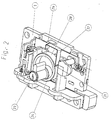
- Fig. 2 shows the arrangement of FIG. 1 with an additionally shown Internal gear 28, which is in operative engagement with the pinion 24.
- the gear ratio of pinion 24 to internal gear 28 can for example are in the range between 1: 1 and 5: 1, in the illustrated Embodiment is 2: 1.
- the internal gear 28 has a bottom surface 29 on its underside provided, on the underside again two not visible in Fig. 2 Driving cams 30 are arranged.
- One of the two drive cams 30 is to act on the holding and blocking element 11 of the Locking plate 10 suitable, while the other driver cam 30 for Actuation of a stop element 25 (see FIG. 1) of the double bolt 7 is provided.
- the internal gear 28 On its outer circumference, the internal gear 28 is offset by two by 180 ° Axial grooves 31 provided with a held on the base plate 1 Detent spring 32 can be brought into engagement in this way Actuation of the lock cylinder 23 only one rotation of the same in Allow clockwise to open the lock according to the invention.
- FIG. 3 The underside of the lock shown in FIG. 3 according to FIGS. 1 and 2 now shows the housing cover 33 with functional elements arranged therein of the lock without the base plate 1.
- a tab 34 is integrally formed on the housing cover 33, which in the illustrated locking position of the lock striking plate 3 and locking elements 8 covered.
- FIG. 3 shows that the housing cover 33 by a plastic cover 39 is surrounded, which in the following in connection with FIG. 5th is explained in more detail.
- Fig. 4 shows the lock according to FIGS. 1 to 3 in its unlocked position with the double bolt retracted 7. Be in this position the two locking elements 8 outside the locking receptacle 9, so that a relative movement between bolt housing 1, 33 and striking plate 3 to open a window.
- FIG. 5 again shows the housing cover 33 with some functional elements of the lock in the position shown in FIG. 4.
- FIG 5 shows a driver cam 30 which is on the underside the bottom surface 29 of the internal gear 28 is arranged.
- the three-part flap 34 can be seen in FIG. 5, which together with the housing cover 33 a receptacle 38 for the Surface element 5 of the striking plate 3 defined.
- the striking plate holder 38 is shaped so that the surface element 5 of tab 34th and housing cover 33 is surrounded on all sides.
- Fig. 5 shows that the housing cover 33 with the exception of the Window facing side on all sides by a plastic cover 39 is surrounded, which ultimately the external appearance of the assembled Castle shapes.
- This plastic cover 39 covers advantageous way with locked lock not only in the striking plate 38 areas of the striking plate 3, but the entire striking plate 3 including bolt 8 and snap element 19. This will trigger an unintentional release of the bolt 7 and one by fast movements of bolt 8 and / or snap element 19 Possible risk of injury avoided.
- the surface element 5 accommodated in the striking plate receptacle 38 of the striking plate 3 is also from the sectional view according to FIG. 6 recognizable.
- the double bolt 7 is in the locked position over the stop surfaces 12, 13 by means of the holding and blocking element 11 of the locking plate 10 blocked (Fig. 1).
- the Pinion 24 By rotating the Pinion 24 by means of a key (not shown) becomes the internal gear 28 (Fig. 2) causes clockwise rotation, causing this leads to that on the underside of the bottom surface 29 of the internal gear 28 arranged a driver cam 30, the striking plate 10 in Direction of arrow A (Fig. 1) moves so that the two stop surfaces 12, 13 are disengaged.
- the snap element 19 bumps to the border of the recess in the opening direction of the window 22 of the striking plate 3, causing rotation of the snap element 19 is effected about the axis 20. This rotational movement of the Snap element 19 ensures that no linear movement when opening the window of the slide 17 takes place.
- the lock When the window is subsequently closed, the lock is first in the position according to FIGS. 4 and 5. In this position it stands Snap element 19 in the striking plate receptacle 38 (Fig. 5).
- An inclined surface of the snap element 19 runs on the surface element 5 of the striking plate 3. Because a rotation of the snap element 19 about the axis 20 starting from the position shown in FIG. 5 of the snap element 19 is only possible in one direction during this run-up of the snap element 19 on the surface element 5 no rotation of the snap element 19, so that the snap element 19 together with the slide 17 linear in the direction of arrow B (Fig. 1) is moved.
Landscapes
- Engineering & Computer Science (AREA)
- Structural Engineering (AREA)
- Lock And Its Accessories (AREA)
- Window Of Vehicle (AREA)
- Glass Compositions (AREA)
- Casings For Electric Apparatus (AREA)
Abstract
Description
- Fig. 1
- eine dreidimensionale Ansicht eines erfindungsgemäßen Fensterschlosses in seiner Verriegelungsstellung ohne Gehäusedeckel und ohne einen Teil des Schloßgetriebes von schräg oben,
- Fig. 2
- eine Ansicht gemäß Fig. 1 mit Schloßgetriebe,
- Fig. 3
- eine dreidimensionale Ansicht eines Fensterschlosses gemäß Fig. 1 in seiner Verriegelungsstellung von schräg unten,
- Fig. 4
- eine dreidimensionale Ansicht eines erfindungsgemäßen Schlosses in seiner Entriegelungsstellung ohne Gehäusedeckel und ohne einen Teil des Schloßgetriebes von schräg oben,
- Fig. 5
- eine dreidimensionale Ansicht eines erfindungsgemäßen Gehäusedeckels mit einzelnen Komponenten des Schlosses von schräg unten, und
- Fig. 6
- einen Schnitt durch einen Teilbereich eines erfindungsgemäßen Schlosses senkrecht zur Fensterebene und parallel zur Bewegungsrichtung des Riegels.
- 1.
- Grundplatte
- 2.
- Bohrungen
- 3.
- Schließblech
- 4.
- Flächenelement
- 5.
- Flächenelement
- 6.
- Bohrungen
- 7.
- Doppelriegel
- 8.
- Riegelelemente
- 9.
- Riegelaufnahmen
- 10.
- Sperrblech
- 11.
- Halte- und Blockierelement
- 12.
- Anschlagfläche
- 13.
- Anschlagfläche
- 14.
- Druckfeder
- 15.
- Schrägfläche
- 16.
- Schrägfläche
- 17.
- Schieber
- 18.
- Druckfeder
- 19.
- Schnappelement
- 20.
- Achse
- 21.
- Schenkelfeder
- 22.
- Ausnehmung
- 23.
- Schließzylinder
- 24.
- Ritzel
- 25.
- Anschlagelement
- 26.
- Anzeigeelement
- 27.
- Zahnsegment
- 28.
- Innenzahnrad
- 29.
- Bodenfläche
- 30.
- Mitnehmernocken
- 31.
- Axialnuten
- 32.
- Rastfeder
- 33.
- Gehäusedeckel
- 34.
- Lasche
- 35.
- Spiralfeder
- 36.
- Anschlagfläche
- 37.
- Anschlagfläche
- 38.
- Schließblechaufnahme
- 39.
- Kunststoffabdeckung
Claims (18)
- Fensterschloß mit einem Riegelgehäuse (1, 33), welches an einem Fensterflügel bzw. einem Fensterrahmen anbringbar ist, und einem Schließblech (3), welches am Fensterrahmen bzw. am Fensterflügel anbringbar ist, bei dem zumindest ein im Riegelgehäuse (1, 33) geführter Riegel (7) mit einer im Schließblech (3) vorhandenen Riegelaufnahme (9) in einer Verriegelungsstellung in Eingriff bringbar ist,
dadurch gekennzeichnet,daß das Riegelgehäuse (1, 33) mit einer in der Verriegelungsstellung sowohl Schließblech (3) als auch Riegel (7) zumindest bereichsweise überdeckenden Lasche (34) versehen ist. - Fensterschloß nach Anspruch 1,
dadurch gekennzeichnet,daß die Lasche (34) das Schließblech (3) und den Riegel (7) in der Verriegelungsstellung auf mehreren Seiten vollständig überdeckt. - Fensterschloß nach Anspruch 2,
dadurch gekennzeichnet,daß die Lasche (34) das Schließblech (3) in der Verriegelungsstellung auf drei Seiten umgibt, so daß die Einheit aus Lasche (34) und Riegelgehäuse (1, 33) eine Schließblechaufnahme (38) bilden, die das Schließblech (3) mit Ausnahme seiner dem Fensterflügel bzw. - rahmen zugewandten Seite allseitig umgreift, wobei insbesondere die Schließblechaufnahme (38) das Schließblech (3) in der Verriegelungsstellung im wesentlichen formschlüssig umgreift. - Fensterschloß nach einem der vorherigen Ansprüche,
dadurch gekennzeichnet,daß eine Automatikverriegelung vorgesehen ist, welche den Riegel (7) beim Schließen des Fensters zwangsläufig in seine Verriegelungsstellung bewegt, und/oder daß der Riegel (7) insbesondere mittels einer Feder (35) in seine Verriegelungsstellung vorgespannt ist, wobei insbesondere die Feder als Spiralfeder (35) ausgebildet ist. - Fensterschloß nach einem der vorherigen Ansprüche,
dadurch gekennzeichnet,daß der Riegel (7) als Doppel- oder Mehrfachriegel ausgebildet ist und das Schließblech (3) eine entsprechende Anzahl von Riegelaufnahmen (9) aufweist, wobei insbesondere zwei oder mehr Riegelelemente (8) miteinander starr gekoppelt, insbesondere einstückig ausgebildet sind. - Fensterschloß nach Anspruch 5,
dadurch gekennzeichnet,daß der als Doppelriegel (7) ausgebildete Riegel mittels zweier Spiralfedern (35) in seine Verriegelungsstellung vorgespannt ist,und/oder daß im Riegelgehäuse (1, 33) ein Schließzylinder (23) zur Betätigung des Riegels (7) von seiner Verriegelungs- in seine Entriegelungsstellung vorgesehen ist. - Fensterschloß nach Anspruch 6,
dadurch gekennzeichnet,daß Schließzylinder (23) und Riegel (7) über einen Zahnradtrieb (24, 28) gekoppelt sind, wobei insbesondere der Zahnradtrieb aus einem starr mit dem Schließzylinder (23) verbunden Ritzel (24), einem mit diesem in Wirkverbindung stehenden Innenzahnrad (28), zumindest einem mit dem Innenzahnrad (28) starr verbundenen Mitnehmernocken (30) und einer starr mit dem Riegel (7) verbundenen Nocken-Anschlagfläche (25) besteht. - Fensterschloß nach Anspruch 7,
dadurch gekennzeichnet,daß Schließzylinder (23) und Innenzahnrad (28) ein Übersetzungsverhältnis im Bereich zwischen 1:1 und 5:1, insbesondere von ungefähr 2:1 aufweisen. - Fensterschloß nach einem der vorherigen Ansprüche,
dadurch gekennzeichnet,daß ein Sperrblech (10) zum Halten des vorgespannten Riegels (7) in seiner Öffnungsstellung vorgesehen ist (Riegel-Haltestellung des Sperrblechs), wobei insbesondere das Sperrblech (10) zusätzlich zur Blockierung des Riegels (7) in seiner Verriegelungsstellung vorgesehen ist (Riegel-Blockierstellung des Sperrblechs). - Fensterschloß nach Anspruch 9,
dadurch gekennzeichnet,daß das Sperrblech (10) insbesondere mittels einer Feder, vorzugsweise mittels einer Druckfeder (14) in die Riegel-Haltestellung und/oder die Riegel-Blockierstellung vorgespannt ist. - Fensterschloß nach einem der Ansprüche 9 oder 10,
dadurch gekennzeichnet,daß das Sperrblech (10) durch das Schließen des Fensters in eine Riegelfreigabestellung bewegbar ist, und/oder daß das Sperrblech (10) durch Betätigung des Schließzylinders (23) in die Riegelfreigabestellung bewegbar ist. - Fensterschloß nach einem der Ansprüche 9 bis 11,
dadurch gekennzeichnet,daß Schließzylinder (23) und Sperrblech (10) über den Zahnradtrieb (24, 28), insbesondere über einen weiteren mit dem Innenzahnrad (28) starr verbundenen Mitnehmernocken (30) und einer starr mit dem Sperrblech (10) verbundenen Nocken-Anschlagfläche (11) miteinander gekoppelt sind. - Fensterschloß nach einem der Ansprüche 9 bis 12,
dadurch gekennzeichnet,daß das Sperrblech (10) beim Schließen des Fensters über einen Schieber (17) in seine Riegelfreigabestellung bewegbar ist, wobei der Schieber (17) durch die Relativbewegung zwischen Riegelgehäuse (1, 33) und Schließblech (3) beaufschlagbar ist, wobei insbesondere der Schieber (17) über ein beim Schließen des Fensters am Schließblech (3) entlanggleitendes Schnappelement (19) beaufschlagbar ist. - Fensterschloß nach Anspruch 13,
dadurch gekennzeichnet,daß das Schnappelement (19) in der Verriegelungsstellung in eine Ausnehmung (22) im Schließblech (3) eingreift, und/oder daß das Schnappelement (19) in der Verriegelungsstellung von der Lasche (34) des Riegelgehäuses (1, 33) überdeckt ist. - Fensterschloß nach einem der Ansprüche 13 oder 14,
dadurch gekennzeichnet,daß das Schnappelement (19) beim Öffnen des Fensters gegenüber dem Schieber (17) insbesondere gegen eine Vorspannung bewegbar ist, wodurch eine Bewegung des Schiebers (17) verhindert ist. - Fensterschloß nach einem der vorherigen Ansprüche,
dadurch gekennzeichnet,daß eine die Ver- bzw. Entriegelungsposition kennzeichnende Anzeige (26) vorgesehen ist, deren Bewegung insbesondere direkt oder indirekt über eine Bewegung des Riegels (7) auslösbar ist, und/oderdaß das Riegelgehäuse (1, 33) zur Anbringung auf dem Fensterflügel und das Schließblech (3) zur Anbringung am Fensterrahmen ausgebildet ist oder umgekehrt. - Fensterschloß nach einem der vorherigen Ansprüche,
dadurch gekennzeichnet,daß das Schließblech (3) als Winkeleisen mit zwei senkrecht aufeinander stehenden Flächenelementen (4, 5) ausgebildet ist, wobei die sich parallel zum Fensterflügel erstreckende Fläche (4) eine Breite von weniger als 30 mm, insbesondere von weniger als 20 mm und vorzugsweise eine Breite von 18 mm aufweist. - Fensterschloß nach einem der vorherigen Ansprüche,
dadurch gekennzeichnet,der Gehäusedeckel (33) mit Ausnahme der dem Fenster zugewandten Seite auf allen Seiten von einer Kunststoffabdeckung (39) umgeben ist, die bei verriegeltem Schloß insbesondere nicht nur die in der Schließblechaufnahme (38) befindlichen Bereiche des Schließblechs (3), sondern das gesamte Schließblech (3) einschließlich Riegel (8) und Schnappelement (19) überdeckt.
Applications Claiming Priority (2)
| Application Number | Priority Date | Filing Date | Title |
|---|---|---|---|
| DE19906622 | 1999-02-17 | ||
| DE19906622A DE19906622A1 (de) | 1999-02-17 | 1999-02-17 | Fensterschloß |
Publications (2)
| Publication Number | Publication Date |
|---|---|
| EP1031687A1 true EP1031687A1 (de) | 2000-08-30 |
| EP1031687B1 EP1031687B1 (de) | 2005-02-09 |
Family
ID=7897783
Family Applications (1)
| Application Number | Title | Priority Date | Filing Date |
|---|---|---|---|
| EP00103164A Expired - Lifetime EP1031687B1 (de) | 1999-02-17 | 2000-02-16 | Fensterschloss |
Country Status (3)
| Country | Link |
|---|---|
| EP (1) | EP1031687B1 (de) |
| AT (1) | ATE288983T1 (de) |
| DE (2) | DE19906622A1 (de) |
Families Citing this family (1)
| Publication number | Priority date | Publication date | Assignee | Title |
|---|---|---|---|---|
| ITMI20070678A1 (it) * | 2007-04-03 | 2008-10-04 | Ik Interklimat S P A | Dispositivo di chiusura di una porta scorrevole di una cella frigorifera |
Citations (7)
| Publication number | Priority date | Publication date | Assignee | Title |
|---|---|---|---|---|
| US1359347A (en) * | 1920-02-24 | 1920-11-16 | Fleisher Max | Lock |
| US1744988A (en) * | 1922-03-03 | 1930-01-28 | Sargent & Co | Lock |
| FR2177148A5 (de) * | 1972-03-21 | 1973-11-02 | Vachette Sa | |
| CH665248A5 (en) * | 1984-11-14 | 1988-04-29 | Brumme Friedrich R Gmbh | Cylinder lock gear drive - has cylinder bore eccentricity in gear ring opposite to that of core |
| EP0670404A1 (de) * | 1994-03-04 | 1995-09-06 | Fritz Fuss GmbH & Co. | Selbstverriegelndes Schloss |
| WO1997001690A1 (en) * | 1995-06-29 | 1997-01-16 | Kibble Anthony W | Bolt unit and frame arrangement |
| EP0816602A2 (de) * | 1996-07-03 | 1998-01-07 | DORMA GmbH + Co. KG | Selbstverriegelndes Einsteckschloss |
Family Cites Families (3)
| Publication number | Priority date | Publication date | Assignee | Title |
|---|---|---|---|---|
| DE8608620U1 (de) * | 1986-03-29 | 1986-06-26 | Adolf Schween GmbH, 4600 Dortmund | Bausatz für eine Schloßstulpe für Türen und Fenster |
| DE8807082U1 (de) * | 1988-05-31 | 1988-09-15 | Schüring GmbH & Co. Fenstertechnologie KG, 5000 Köln | Vorrichtung zur Führung der Schrauben zum Befestigen eines Stulpbleches eines Einsteckschlosses |
| DE9401170U1 (de) * | 1994-01-25 | 1995-06-08 | Niemann, Hans Dieter, 50169 Kerpen | Riegelschloß für Tür-, Fenster- o.dgl. Flügel |
-
1999
- 1999-02-17 DE DE19906622A patent/DE19906622A1/de not_active Withdrawn
-
2000
- 2000-02-16 DE DE50009445T patent/DE50009445D1/de not_active Expired - Lifetime
- 2000-02-16 EP EP00103164A patent/EP1031687B1/de not_active Expired - Lifetime
- 2000-02-16 AT AT00103164T patent/ATE288983T1/de not_active IP Right Cessation
Patent Citations (7)
| Publication number | Priority date | Publication date | Assignee | Title |
|---|---|---|---|---|
| US1359347A (en) * | 1920-02-24 | 1920-11-16 | Fleisher Max | Lock |
| US1744988A (en) * | 1922-03-03 | 1930-01-28 | Sargent & Co | Lock |
| FR2177148A5 (de) * | 1972-03-21 | 1973-11-02 | Vachette Sa | |
| CH665248A5 (en) * | 1984-11-14 | 1988-04-29 | Brumme Friedrich R Gmbh | Cylinder lock gear drive - has cylinder bore eccentricity in gear ring opposite to that of core |
| EP0670404A1 (de) * | 1994-03-04 | 1995-09-06 | Fritz Fuss GmbH & Co. | Selbstverriegelndes Schloss |
| WO1997001690A1 (en) * | 1995-06-29 | 1997-01-16 | Kibble Anthony W | Bolt unit and frame arrangement |
| EP0816602A2 (de) * | 1996-07-03 | 1998-01-07 | DORMA GmbH + Co. KG | Selbstverriegelndes Einsteckschloss |
Also Published As
| Publication number | Publication date |
|---|---|
| DE19906622A1 (de) | 2000-08-24 |
| DE50009445D1 (de) | 2005-03-17 |
| EP1031687B1 (de) | 2005-02-09 |
| ATE288983T1 (de) | 2005-02-15 |
Similar Documents
| Publication | Publication Date | Title |
|---|---|---|
| EP2213817B1 (de) | Schloss, insbesondere Schwenkriegelschloss, mit erhöhter Schutzwirkung | |
| EP0954667B1 (de) | Schloss mit falle für tür oder fenster | |
| DE69701236T2 (de) | Einsteckschloss | |
| EP1049846B1 (de) | Türschloss für eine ganzglastür mit feststehendem glasseitenteil | |
| DE69007236T2 (de) | Vorrichtung für Verriegelung und Antrieb eines beweglichen Teiles zwischen einer ersten und einer zweiten Position und damit versehene Fahrzeugtür. | |
| DE4114007A1 (de) | Treibstangenverschluss | |
| EP1031687B1 (de) | Fensterschloss | |
| DE3931101A1 (de) | Automatisch verriegelndes schloss | |
| DE4019783C2 (de) | ||
| DE2340580A1 (de) | Einsteckschloss, insbesondere fuer rohrrahmentueren | |
| EP1344883B1 (de) | Verriegelungseinrichtung für eine Tür | |
| DE102008009511A1 (de) | Schloss mit einer verbesserten Schließmechanik | |
| EP0795664B1 (de) | Einsteckschloss | |
| DE102009006497A1 (de) | Schloss, insbesondere Schubriegelschloss, mit erhöhter Schutzwirkung | |
| DE19538320A1 (de) | Verriegelungsschloß | |
| EP0515834B1 (de) | Schubriegelschloss | |
| DE19526660A1 (de) | Elektromechanisches Schloß | |
| DE102007035123B4 (de) | Kippsicherung | |
| DE102005000078A1 (de) | Schloss | |
| DE9414137U1 (de) | Schloß | |
| DE2745191C2 (de) | Steckschlüsselschloß | |
| DE69304074T2 (de) | Schloss mit einer verriegelungsvorrichtung für das schlossbetätigungselement | |
| DE102019114188A1 (de) | Stangenverschluss | |
| DE9321038U1 (de) | Selbstverriegelndes Sicherheitstürschloß | |
| DE102012111537A1 (de) | Schloss mit einer freigebbaren Dreheinheit |
Legal Events
| Date | Code | Title | Description |
|---|---|---|---|
| PUAI | Public reference made under article 153(3) epc to a published international application that has entered the european phase |
Free format text: ORIGINAL CODE: 0009012 |
|
| AK | Designated contracting states |
Kind code of ref document: A1 Designated state(s): AT BE CH DE FR GB LI NL |
|
| AX | Request for extension of the european patent |
Free format text: AL;LT;LV;MK;RO;SI |
|
| 17P | Request for examination filed |
Effective date: 20001106 |
|
| AKX | Designation fees paid |
Free format text: AT BE CH DE FR GB LI NL |
|
| 17Q | First examination report despatched |
Effective date: 20031017 |
|
| GRAP | Despatch of communication of intention to grant a patent |
Free format text: ORIGINAL CODE: EPIDOSNIGR1 |
|
| RBV | Designated contracting states (corrected) |
Designated state(s): AT BE CH CY DE DK ES FI FR GB GR IE IT LI LU MC NL PT SE |
|
| GRAS | Grant fee paid |
Free format text: ORIGINAL CODE: EPIDOSNIGR3 |
|
| GRAA | (expected) grant |
Free format text: ORIGINAL CODE: 0009210 |
|
| AK | Designated contracting states |
Kind code of ref document: B1 Designated state(s): AT BE CH CY DE DK ES FI FR GB GR IE IT LI LU MC NL PT SE |
|
| PG25 | Lapsed in a contracting state [announced via postgrant information from national office to epo] |
Ref country code: IT Free format text: LAPSE BECAUSE OF FAILURE TO SUBMIT A TRANSLATION OF THE DESCRIPTION OR TO PAY THE FEE WITHIN THE PRESCRIBED TIME-LIMIT;WARNING: LAPSES OF ITALIAN PATENTS WITH EFFECTIVE DATE BEFORE 2007 MAY HAVE OCCURRED AT ANY TIME BEFORE 2007. THE CORRECT EFFECTIVE DATE MAY BE DIFFERENT FROM THE ONE RECORDED. Effective date: 20050209 Ref country code: FI Free format text: LAPSE BECAUSE OF FAILURE TO SUBMIT A TRANSLATION OF THE DESCRIPTION OR TO PAY THE FEE WITHIN THE PRESCRIBED TIME-LIMIT Effective date: 20050209 Ref country code: GB Free format text: LAPSE BECAUSE OF FAILURE TO SUBMIT A TRANSLATION OF THE DESCRIPTION OR TO PAY THE FEE WITHIN THE PRESCRIBED TIME-LIMIT Effective date: 20050209 Ref country code: FR Free format text: LAPSE BECAUSE OF NON-PAYMENT OF DUE FEES Effective date: 20050209 Ref country code: IE Free format text: LAPSE BECAUSE OF FAILURE TO SUBMIT A TRANSLATION OF THE DESCRIPTION OR TO PAY THE FEE WITHIN THE PRESCRIBED TIME-LIMIT Effective date: 20050209 |
|
| REG | Reference to a national code |
Ref country code: GB Ref legal event code: FG4D Free format text: NOT ENGLISH |
|
| REG | Reference to a national code |
Ref country code: CH Ref legal event code: EP |
|
| PG25 | Lapsed in a contracting state [announced via postgrant information from national office to epo] |
Ref country code: CY Free format text: LAPSE BECAUSE OF FAILURE TO SUBMIT A TRANSLATION OF THE DESCRIPTION OR TO PAY THE FEE WITHIN THE PRESCRIBED TIME-LIMIT Effective date: 20050216 Ref country code: AT Free format text: LAPSE BECAUSE OF NON-PAYMENT OF DUE FEES Effective date: 20050216 Ref country code: LU Free format text: LAPSE BECAUSE OF NON-PAYMENT OF DUE FEES Effective date: 20050216 |
|
| PGFP | Annual fee paid to national office [announced via postgrant information from national office to epo] |
Ref country code: NL Payment date: 20050218 Year of fee payment: 6 |
|
| PG25 | Lapsed in a contracting state [announced via postgrant information from national office to epo] |
Ref country code: CH Free format text: LAPSE BECAUSE OF NON-PAYMENT OF DUE FEES Effective date: 20050228 Ref country code: LI Free format text: LAPSE BECAUSE OF NON-PAYMENT OF DUE FEES Effective date: 20050228 Ref country code: MC Free format text: LAPSE BECAUSE OF NON-PAYMENT OF DUE FEES Effective date: 20050228 |
|
| REG | Reference to a national code |
Ref country code: IE Ref legal event code: FG4D Free format text: GERMAN |
|
| PGFP | Annual fee paid to national office [announced via postgrant information from national office to epo] |
Ref country code: BE Payment date: 20050311 Year of fee payment: 6 |
|
| REF | Corresponds to: |
Ref document number: 50009445 Country of ref document: DE Date of ref document: 20050317 Kind code of ref document: P |
|
| PG25 | Lapsed in a contracting state [announced via postgrant information from national office to epo] |
Ref country code: SE Free format text: LAPSE BECAUSE OF FAILURE TO SUBMIT A TRANSLATION OF THE DESCRIPTION OR TO PAY THE FEE WITHIN THE PRESCRIBED TIME-LIMIT Effective date: 20050509 Ref country code: GR Free format text: LAPSE BECAUSE OF FAILURE TO SUBMIT A TRANSLATION OF THE DESCRIPTION OR TO PAY THE FEE WITHIN THE PRESCRIBED TIME-LIMIT Effective date: 20050509 Ref country code: DK Free format text: LAPSE BECAUSE OF FAILURE TO SUBMIT A TRANSLATION OF THE DESCRIPTION OR TO PAY THE FEE WITHIN THE PRESCRIBED TIME-LIMIT Effective date: 20050509 |
|
| PG25 | Lapsed in a contracting state [announced via postgrant information from national office to epo] |
Ref country code: ES Free format text: LAPSE BECAUSE OF FAILURE TO SUBMIT A TRANSLATION OF THE DESCRIPTION OR TO PAY THE FEE WITHIN THE PRESCRIBED TIME-LIMIT Effective date: 20050520 |
|
| GBV | Gb: ep patent (uk) treated as always having been void in accordance with gb section 77(7)/1977 [no translation filed] |
Effective date: 20050209 |
|
| REG | Reference to a national code |
Ref country code: IE Ref legal event code: FD4D |
|
| REG | Reference to a national code |
Ref country code: CH Ref legal event code: PL |
|
| PLBE | No opposition filed within time limit |
Free format text: ORIGINAL CODE: 0009261 |
|
| STAA | Information on the status of an ep patent application or granted ep patent |
Free format text: STATUS: NO OPPOSITION FILED WITHIN TIME LIMIT |
|
| 26N | No opposition filed |
Effective date: 20051110 |
|
| PG25 | Lapsed in a contracting state [announced via postgrant information from national office to epo] |
Ref country code: BE Free format text: LAPSE BECAUSE OF NON-PAYMENT OF DUE FEES Effective date: 20060228 |
|
| EN | Fr: translation not filed | ||
| PG25 | Lapsed in a contracting state [announced via postgrant information from national office to epo] |
Ref country code: NL Free format text: LAPSE BECAUSE OF NON-PAYMENT OF DUE FEES Effective date: 20060901 |
|
| NLV4 | Nl: lapsed or anulled due to non-payment of the annual fee |
Effective date: 20060901 |
|
| BERE | Be: lapsed |
Owner name: *ABUS AUGUST BREMICKER SOHNE K.G. Effective date: 20060228 |
|
| PG25 | Lapsed in a contracting state [announced via postgrant information from national office to epo] |
Ref country code: PT Free format text: LAPSE BECAUSE OF NON-PAYMENT OF DUE FEES Effective date: 20050709 |
|
| PGFP | Annual fee paid to national office [announced via postgrant information from national office to epo] |
Ref country code: DE Payment date: 20160429 Year of fee payment: 17 |
|
| REG | Reference to a national code |
Ref country code: DE Ref legal event code: R119 Ref document number: 50009445 Country of ref document: DE |
|
| PG25 | Lapsed in a contracting state [announced via postgrant information from national office to epo] |
Ref country code: DE Free format text: LAPSE BECAUSE OF NON-PAYMENT OF DUE FEES Effective date: 20170901 |