EP1030954B1 - Support sheet for ground or wall coverings which are exposed to the weather - Google Patents
Support sheet for ground or wall coverings which are exposed to the weather Download PDFInfo
- Publication number
- EP1030954B1 EP1030954B1 EP98954391A EP98954391A EP1030954B1 EP 1030954 B1 EP1030954 B1 EP 1030954B1 EP 98954391 A EP98954391 A EP 98954391A EP 98954391 A EP98954391 A EP 98954391A EP 1030954 B1 EP1030954 B1 EP 1030954B1
- Authority
- EP
- European Patent Office
- Prior art keywords
- projections
- cup
- support sheet
- projecting
- wall
- Prior art date
- Legal status (The legal status is an assumption and is not a legal conclusion. Google has not performed a legal analysis and makes no representation as to the accuracy of the status listed.)
- Expired - Lifetime
Links
Images


Classifications
-
- E—FIXED CONSTRUCTIONS
- E04—BUILDING
- E04F—FINISHING WORK ON BUILDINGS, e.g. STAIRS, FLOORS
- E04F13/00—Coverings or linings, e.g. for walls or ceilings
- E04F13/02—Coverings or linings, e.g. for walls or ceilings of plastic materials hardening after applying, e.g. plaster
- E04F13/04—Bases for plaster
-
- E—FIXED CONSTRUCTIONS
- E04—BUILDING
- E04D—ROOF COVERINGS; SKY-LIGHTS; GUTTERS; ROOF-WORKING TOOLS
- E04D11/00—Roof covering, as far as not restricted to features covered by only one of groups E04D1/00 - E04D9/00; Roof covering in ways not provided for by groups E04D1/00 - E04D9/00, e.g. built-up roofs, elevated load-supporting roof coverings
- E04D11/005—Supports for elevated load-supporting roof coverings
-
- E—FIXED CONSTRUCTIONS
- E04—BUILDING
- E04F—FINISHING WORK ON BUILDINGS, e.g. STAIRS, FLOORS
- E04F13/00—Coverings or linings, e.g. for walls or ceilings
- E04F13/07—Coverings or linings, e.g. for walls or ceilings composed of covering or lining elements; Sub-structures therefor; Fastening means therefor
- E04F13/08—Coverings or linings, e.g. for walls or ceilings composed of covering or lining elements; Sub-structures therefor; Fastening means therefor composed of a plurality of similar covering or lining elements
- E04F13/0869—Coverings or linings, e.g. for walls or ceilings composed of covering or lining elements; Sub-structures therefor; Fastening means therefor composed of a plurality of similar covering or lining elements having conduits for fluids
-
- E—FIXED CONSTRUCTIONS
- E04—BUILDING
- E04F—FINISHING WORK ON BUILDINGS, e.g. STAIRS, FLOORS
- E04F15/00—Flooring
- E04F15/18—Separately-laid insulating layers; Other additional insulating measures; Floating floors
-
- E—FIXED CONSTRUCTIONS
- E04—BUILDING
- E04F—FINISHING WORK ON BUILDINGS, e.g. STAIRS, FLOORS
- E04F15/00—Flooring
- E04F15/18—Separately-laid insulating layers; Other additional insulating measures; Floating floors
- E04F15/182—Underlayers coated with adhesive or mortar to receive the flooring
-
- E—FIXED CONSTRUCTIONS
- E04—BUILDING
- E04F—FINISHING WORK ON BUILDINGS, e.g. STAIRS, FLOORS
- E04F15/00—Flooring
- E04F15/18—Separately-laid insulating layers; Other additional insulating measures; Floating floors
- E04F15/182—Underlayers coated with adhesive or mortar to receive the flooring
- E04F15/183—Underlayers coated with adhesive or mortar to receive the flooring for areas prone to frost damage, e.g. for balconies or terraces
-
- E—FIXED CONSTRUCTIONS
- E04—BUILDING
- E04F—FINISHING WORK ON BUILDINGS, e.g. STAIRS, FLOORS
- E04F15/00—Flooring
- E04F15/18—Separately-laid insulating layers; Other additional insulating measures; Floating floors
- E04F15/185—Underlayers in the form of studded or ribbed plates
-
- F—MECHANICAL ENGINEERING; LIGHTING; HEATING; WEAPONS; BLASTING
- F24—HEATING; RANGES; VENTILATING
- F24D—DOMESTIC- OR SPACE-HEATING SYSTEMS, e.g. CENTRAL HEATING SYSTEMS; DOMESTIC HOT-WATER SUPPLY SYSTEMS; ELEMENTS OR COMPONENTS THEREFOR
- F24D3/00—Hot-water central heating systems
- F24D3/12—Tube and panel arrangements for ceiling, wall, or underfloor heating
- F24D3/14—Tube and panel arrangements for ceiling, wall, or underfloor heating incorporated in a ceiling, wall or floor
- F24D3/141—Tube mountings specially adapted therefor
- F24D3/142—Tube mountings specially adapted therefor integrated in prefab construction elements
-
- Y—GENERAL TAGGING OF NEW TECHNOLOGICAL DEVELOPMENTS; GENERAL TAGGING OF CROSS-SECTIONAL TECHNOLOGIES SPANNING OVER SEVERAL SECTIONS OF THE IPC; TECHNICAL SUBJECTS COVERED BY FORMER USPC CROSS-REFERENCE ART COLLECTIONS [XRACs] AND DIGESTS
- Y02—TECHNOLOGIES OR APPLICATIONS FOR MITIGATION OR ADAPTATION AGAINST CLIMATE CHANGE
- Y02B—CLIMATE CHANGE MITIGATION TECHNOLOGIES RELATED TO BUILDINGS, e.g. HOUSING, HOUSE APPLIANCES OR RELATED END-USER APPLICATIONS
- Y02B30/00—Energy efficient heating, ventilation or air conditioning [HVAC]
Definitions
- the invention relates to a carrier web for weather influences exposed floor or wall coverings, which a rigid plastic film with a pattern from the film level protruding, spaced apart well-like Projections with essentially flat, parallel has floor or cover walls running to the film plane, the cup-like projections alternating from the opposite sides of the plastic film to step forward.
- connection heights 150 mm prescribed, unless that is strong Rainfall on the top of the balcony or terrace Rain water provided in front of the door openings Drainage grate can be removed. Then can the connection height can be reduced to 50 mm.
- the amount of the original Covering and screed layer not sufficient to include such To be able to effectively install drainage grates because none sufficient drainage of rainwater can be achieved is.
- DE-U-92 09 520 describes a carrier for useful coverings, known as flexible web provided as walking or driving surfaces, which of a medium, relatively thick flexible carrier layer made of rubber with from the opposite Known protruding sides in one piece.
- the projections on the underside keep the carrier layer at a distance above the actual surface on which the walking or driving surfaces are to be applied so that between the support layer and the substrate with each other connected cavities are formed, over which of the Upper side made of drainage channels passing through the carrier layer incoming liquid, e.g. Surface water discharged can be.
- the one on the top of the known Walking or driving surface to be applied to the carrier web should e.g. via a bed of substrate non-adherent on the carrier web be applied.
- the invention has for its object a relative thin-layer carrier web for flooring in special cases to create wall coverings that - especially in In case of subsequent renovation - a thin covering construction on sealed surfaces, the actual walkable or exposed to the weather Cover firmly with mortar or adhesive Carrier web is connectable and the carrier web during The mortar sets or the adhesive hardens offers.
- This object is achieved in that the outside of the floor or top walls of one Cup-like projections appearing on the side of the film plane one for gaseous or vaporous, liquid and pasty Media permeable mesh fabric of high strength is provided.
- This mesh fabric not only stabilizes the carrier web, but practically forms a reinforcement in of those holding the tiles or floor slabs on the carrier web Mortar or adhesive layer, causing the emergence is counteracted by cracks in the mortar layer.
- the grid fabric is preferably - for example by gluing - firmly adhering to the floor or deck walls the cup-like projections applied.
- Cup-like projections are expediently gas, vapor and liquid-permeable through openings are provided, through which emerging from the mortar or adhesive layer Moisture or water vapor is removed. Also ventilation and drying the mortar or adhesive layer this ensures from the underside of the carrier web. Likewise, residual moisture from inside can also Subsequent screeds through the through openings vent to the outside.
- the through openings can be of slot-like Through-cuts of the cup-like projections are formed, which each have the bottom wall and at least one subsequent one Section of the peripheral wall of the respective Push through the cup-like projection.
- Each additional lead can have a smaller height have as those appearing on the same page cup-like projections.
- the height of the protrusion becomes one Depends on the composition of the mortar material and choose the amount of shrinkage.
- any additional Protrusion a rib-like elongated shape to have.
- each additional protrusion but also several individual protrusions between adjacent well-like projections be provided.
- any additional projection is integrally formed from the material of the carrier web.
- Forming projections massively, but it makes sense that additional projections - for the rest, as well as the cup-like Projections - from the plastic film in one To shape the thermoforming process. This ensures that no additional plastic material for these projections is needed.
- the well-like cells appearing on the same side Projections preferably have the same shape and same average dimensions and same height. there can the cup-like appearing on opposite sides Projections also differ in height and / or different cross-sectional shapes or dimensions to have.
- the cup-like projections in the top view of their open mouth or the bottom or Cover wall may be limited in a circle, although basically also other cup shapes, e.g. with long oval or diamond-shaped as well as rectangular or square boundary are realizable.
- the design can be either be taken that several in the circumferential direction of the well-like Projections offset from each other radially projecting low approaches or alternatively one on the peripheral wall of the cup-like projections all the way down Ring approach is provided.
- the rigid one Plastic film at least on two opposite parallel ones Edges narrow side edge areas without of the Have projections protruding from the film plane, each of which overlapping with laterally bordering areas similar carrier webs can be brought.
- the Possibility of overlapping laying of the carrier sheets is therefore also suitable for use on large terraces and Balconies possible.
- Protruding cup-like floor or wall coverings Projections pointing well-like projections can an additional heat and / or soundproofing covering is provided his. Additional insulation is for example then expedient if the carrier web according to the invention under wall coverings to be provided on the outer walls of the building is provided.
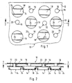
- Figures 1 and 2 show one in its entirety at 10 designated embodiment of an inventive Support web.
- the carrier web originally consists of a flat thin, rigid plastic film 12, in which well-like in a regular pattern Wells 14 and 16 from the film level opposite sides are molded.
- the protrusions 14 and 16 are each circularly limited in the illustrated case and by a respective flat bottom wall 18 or top wall 20 completed.
- the depth of the protrusions 14 and 16 measured from the plane of the film 12 at illustrated embodiment in the order of preferably 5 to 10 mm, so that the carrier web 10th thus has a total thickness of approximately 10 to 20 mm, whereby the cup-like projections also have a great depth can and thus a much greater total thickness of the Foil sheet can be realized.
- Projections 14 have a significantly larger diameter than that protruding from the drawing plane to the viewer in FIG. 1 Have projections 16.
- On the top walls 20 of the Projections 16 is a high-strength one, shown only in FIG. 2 Lattice fabric 22 adhered, which - like explained in more detail below in connection with FIG. 3 becomes - for armoring and holding one on top the carrier web 10 applied mortar or adhesive.
- the adhesive connection of the mesh fabric 22 on the top walls 20 of the cup-like projections 16 can be glued or - due to the thermoplastic properties the material of the film web 12 - by hot pressing in the outside of the top walls 20.
- the mesh 22 is selected in its mesh size so that even more vivid mortar or glue through the mesh through to the facing top of the film web 12 and can penetrate into the cup-shaped projections 14.
- the projections 14 In the bottom walls 18 of the projections 14 are shown in the Two slot-like through openings 24 in each case provided that also extends a little further into the peripheral wall the projections 14 extend and break through them, as can be seen in Fig. 2.
- the slit-like Openings that, for example, after the stamping or Deep drawing the cup-like projections 14, 16 into the Allow film web 12 to be milled into the carrier web that is, the passage of liquid and water vapor to the underside of the carrier web, which means not only curing or binding one applied on the top Mortar or adhesive layer supports, but also the Passage or the evaporation of subsequently into the Mortar layer of rainwater penetrated to the bottom the carrier web is possible, which then over the remaining cavity between the projections 14 discharged can be.
- the carrier web according to the invention can therefore also subsequent renovation of originally not drained Balconies or terraces can be used, then in the connection area at door openings to the terrace or balcony low drainage grids can be provided, which rainwater accumulating there to the underside of the carrier web let pass. With this it is possible, even such Retrofitting and refurbishing balconies or terraces drain where those in such door areas for not drained balconies prescribed connection height of approx. 150 mm is not given.
- FIG 3 shows an installation example of the carrier web 10 one sealed at the top by a seal 26 3alkon- or terrace-concrete support plate 28 shown. It it can be seen that the bottom walls 18 of the projections 14 of the Carrier web 10 simply placed on the seal 26 are, i.e. that an adhesive bond between the carrier web 10 and the concrete support plate 28 does not exist, so that with different horizontal expansions of the support plate 28 and the carrier web 10 no shear stresses occur between the carrier sheets and the seal 26 and can damage the seal.
- Fig. 3 it can also be seen that the carrier web 10 on the side facing away from the seal 26 completely with an adhesive mortar is filled, which also in a thin layer still stands over the mesh 22 and the bottom of ceramic tiles 32 adhering to the carrier web 10 holds.
- the joints between the tiles 32 are with a suitable grout 34 grouted.
- the mesh 22 is a reinforcement forms the hardened or set mortar layer, which is the formation and opening of at least larger ones Cracks in the mortar prevented.
- Fig. 4 shows the use of one of the carrier web 10 in essentially corresponding carrier web 10 'in vertical Arrangement, such as on the outer wall of a Building as rear-ventilated carrier sheet for exterior plaster 30 ' and / or for holding a veneer - not shown with ceramic tiles, clinker straps, shingles etc. can serve.
- the basic structure of the carrier web 10 ' corresponds to that in connection with FIGS. 1 to 3 described carrier web 10, in the case shown additionally on the underside facing the building wall an additional thermal insulation layer 36 made of rigid foam sheet material or mineral felt sheets is provided.
- This Thermal barrier layer can be part of the carrier web 10 ', i.e. with the Bottoms 18 of the cup-like projections 14 glued or in be connected in another way.
- the thermal barrier coating 36 also made separately and before application the carrier web 10 'on the - not shown - Building wall must be applied in an adherent manner, with one expediently mechanical fastening using plate anchors or the like chosen becomes.
- the carrier web 10 ' only for rear ventilation of the outer wall covering of the building, i.e. of the plaster or tiles, Straps, shingles etc. can be used at the Carrier web 10 provided through opening 24 are also omitted, although it also applies to the carrier web 10 '
- the advantage is that they set or harden faster and allow the plaster or mortar layer 30 'to dry through. The drying of the plaster 30 'when wet is supported by driving rain.
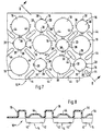
- FIGS. 5 and 6 show a further modified carrier web 10 ", which - corresponding to the carrier webs 10 and 10 '- from an originally flat, rigid plastic film 12 molded out on opposite sides has cup-like projections 14 and 16, of which in special case the projections 16 a comparatively something larger diameter and greater height than the corresponding ones Have wells of the carrier web 10 and 10 '.
- FIGS. 7 and 8 show a modified carrier web 10 "'shown, the basic structure of the carrier web 10" 5 corresponds to. However, the carrier web 10 "'points additional protrusions 44 on the viewer facing side of the carrier web between two adjacent, well-shaped projections on the lining side 16 are arranged. As can be seen is between the adjacent well-like projections 16 only one single additional protrusion with an elongated Form provided. However, it is quite possible instead of the individual several additional protrusions between the neighboring ones to arrange cup-like projections 16, the Shape can also be selected, for example, round or angular.
- Fig. 8 it can be seen that the projections 44 are smaller Have height than the cup-like projections 16.
- Das Mortar material can have lower additional protrusions applied particularly well to the carrier web 10 ′′ and be evenly distributed. However, it is also possible to form the additional projections 44 as high as the cup-like projections 16.
Abstract
Description
Die Erfindung betrifft eine Trägerbahn für Witterungseinflüssen ausgesetzte Boden- oder Wandbeläge, welche eine steife Kunststoffolie mit einem Muster von aus der Folienebene vortretenden, voneinander beabstandeten näpfchenartigen Vorsprüngen mit im wesentlichen ebenflächigen, parallel zur Folienebene verlaufenden Boden- bzw. Deckwänden aufweist, wobei die näpfchenartigen Vorsprünge abwechselnd von den gegenüberliegenden Seiten der Kunststofffolie vortreten.The invention relates to a carrier web for weather influences exposed floor or wall coverings, which a rigid plastic film with a pattern from the film level protruding, spaced apart well-like Projections with essentially flat, parallel has floor or cover walls running to the film plane, the cup-like projections alternating from the opposite sides of the plastic film to step forward.
Zwischen der heute durch aufkaschierte Folien oder Bitumenbahnen oder - in neuerer Zeit - auch durch Dichtschlämme oder Flüssigfolie gegen Eindringen von Feuchtigkeit abgedichteten Oberseite von Witterungseinflüssen ausgesetzten Untergründen, wie Balkonen oder Terrassen werden heute in vielen Fällen zwischen dem eigentlichen Bodenbelag in Form von Beton-Tragplatten oder Fliesen und der abgedichteten Oberfläche Trägerbahnen angeordnet, welche durch die Beläge bzw. deren Fugen eindringende Regenwasser in Kanälen sammeln und abführen. Über die Kanäle wird auch eine Belüftung und Durchtrocknung des die Beläge fixierenden Mörtels bzw. Klebers von der Unterseite aus erreicht. Eine solche Trägerbahn ist z.B. in dem nicht vorveröffentlichten DE-Gebrauchsmuster 298 06 561.4 beschrieben, die insbesondere für die Dünnbettverlegung von Boden-Fliesen oder Beton-Trägerplatten geeignet ist und sich - insbesondere auch für Reparaturen von schadhaft gewordenen Balkon- oder Terrassenbeläge anbietet. Dabei hat sich als zusätzlicher Vorteil dieser aus einer eigensteifen, durch aufeinanderfolgend in dichtem Abstand parallel verlaufende streifenförmige, jeweils gegensinnig umgekantete Abschnitte mit abwechselnd an der Ober- und der Unterseite gebildeten Kanälen versehene Kunststoffolie herausgestellt, daß die Folie auf der Abdichtung des Untergrunds nur lose aufgesetzt ist, so daß bei unterschiedlichen Dehnungen des Belags und des Untergrunds - beispielsweise infolge von sich ändernden Temperaturen - keine Scherkräfte vom Belag in die Abdichtschicht übertragen werden. Die an der Oberseite vorgesehenen Kanäle stehen dabei mit den zur Unterseite, d.h. der abgedichteten Oberfläche des Untergrunds weisenden Kanälen über durchgehende Öffnungen in Verbindung, so daß also von der Belagseite in den Mörtel oder Kleber und die nach oben offenen mörtelgefüllten Kanäle eingedrungenes Wasser durch die Öffnung in die an der Unterseite vorgesehenen offenen Kanäle abgeführt und die Mörtelschicht so entwässert und getrocknet werden kann. Allerdings ist das Entwässerungsvermögen begrenzt, wodurch sich insbesondere bei der Sanierung von Balkonen und Terrassen, bei denen im Bereich von Türen in der Gebäudewandung keine ausreichende Anschlußhöhe gegeben ist, Probleme ergeben. Hier sind Anschlußhöhen von 150 mm vorgeschrieben, sofern nicht das bei starken Regenfällen auf der Balkon- oder Terrassenoberseite anfallende Niederschlagswasser über vor den Türdurchbrüchen vorgesehenen Drainagerosten abgeführt werden kann. Dann kann die Anschlußhöhe auf 50 mm reduziert werden. Insbesondere bei Balkonsanierungen ist aber die Höhe der ursprünglichen Belags- und Estrichschicht nicht hinreichend, um hier solche Drainroste wirksam installieren zu können, weil keine ausreichende Abfuhr des Niederschlagswasser verwirklichbar ist. Between those today with laminated foils or bitumen sheets or - more recently - also through sealing sludge or liquid film sealed against the ingress of moisture Top exposed to weather conditions Substrates such as balconies or terraces are in today many cases between the actual flooring in shape of concrete slabs or tiles and the sealed Surface carrier webs arranged through the coverings or collect the joints penetrating rainwater in channels and lead away. There is also ventilation through the channels and drying of the mortar fixing the coverings or Adhesive reached from the bottom. Such a carrier web is e.g. in the unpublished DE utility model 298 06 561.4 described, in particular for thin bed laying of floor tiles or Concrete base boards is suitable and - in particular also for repairs of damaged balcony or Offers terrace coverings. It has proven to be an additional one Take advantage of this from an inherently rigid, through successive strip-shaped, parallel, closely spaced sections turned in opposite directions with alternating channels formed on the top and bottom provided plastic film that the film is only loosely attached to the sealing of the subsurface, so that with different stretching of the covering and the Underground - for example as a result of changing Temperatures - no shear forces from the covering into the sealing layer be transmitted. The ones provided at the top Channels are at the bottom, i.e. the sealed surface of the underground channels through through openings in connection, so that from the topping in the mortar or glue and the up open mortar-filled channels the opening in the open provided at the bottom Channels drained and the mortar layer so drained and can be dried. However, the drainage capacity limited, which is particularly important when renovating of balconies and terraces in the area of Doors in the building wall do not have a sufficient connection height there are problems. Here are connection heights of 150 mm prescribed, unless that is strong Rainfall on the top of the balcony or terrace Rain water provided in front of the door openings Drainage grate can be removed. Then can the connection height can be reduced to 50 mm. In particular for balcony renovations, however, is the amount of the original Covering and screed layer not sufficient to include such To be able to effectively install drainage grates because none sufficient drainage of rainwater can be achieved is.
Aus der DE-U-92 09 520 ist eine als Träger für Nutzbeläge, wie Geh- oder Fahrbeläge vorgesehene flexible Bahn bekannt, welche von einer mittleren, relativ dicken flexiblen Trägerschicht aus Kautschuk mit von den gegenüberliegenden Seiten einstückig vortretenden Vorsprüngen bekannt. Die unterseitigen Vorsprünge halten die Trägerschicht mit Abstand oberhalb des eigentlichen Untergrunds, auf welchem die Geh- oder Fahrbeläge aufgebracht werden sollen, so dass zwischen der Trägerschicht und dem Untergrund miteinander verbundene Hohlräume gebildet sind, über welche von der Oberseite aus über die Trägerschicht durchsetzende Drainagekanäle zutretende Flüssigkeit, z.B. Oberflächenwasser abgeführt werden kann. Der auf der Oberseite der bekannten Trägerbahn aufzubringende Geh- oder Fahrbelag soll dabei, z.B. über eine Substratschüttung nichthaftend auf der Trägerbahn aufgebracht werden. DE-U-92 09 520 describes a carrier for useful coverings, known as flexible web provided as walking or driving surfaces, which of a medium, relatively thick flexible carrier layer made of rubber with from the opposite Known protruding sides in one piece. The projections on the underside keep the carrier layer at a distance above the actual surface on which the walking or driving surfaces are to be applied so that between the support layer and the substrate with each other connected cavities are formed, over which of the Upper side made of drainage channels passing through the carrier layer incoming liquid, e.g. Surface water discharged can be. The one on the top of the known Walking or driving surface to be applied to the carrier web should e.g. via a bed of substrate non-adherent on the carrier web be applied.
Der Erfindung liegt die Aufgabe zugrunde, eine relativ dünnschichtige Trägerbahn für Boden- in Sonderfällen aber auch Wandbeläge zu schaffen, die - insbesondere auch im Falle nachträglicher Sanierung - eine dünne Belagskonstruktion auf abgedichteten Untergründen ermöglicht, wobei der eigentliche begehbare bzw. den Witterungseinflüssen ausgesetzte Belag durch Mörtel oder Kleber fest haftend mit der Trägerbahn verbindbar ist und die Trägerbahn während des Abbindens des Mörtels bzw. des Aushärtens des Klebers Halt bietet.The invention has for its object a relative thin-layer carrier web for flooring in special cases to create wall coverings that - especially in In case of subsequent renovation - a thin covering construction on sealed surfaces, the actual walkable or exposed to the weather Cover firmly with mortar or adhesive Carrier web is connectable and the carrier web during The mortar sets or the adhesive hardens offers.
Ausgehend von einer Trägerbahn der eingangs erwähnten Art wird diese Aufgabe erfindungsgemäß dadurch gelöst, daß auf der Außenseite der Boden- bzw. Deckwände von von einer Seite der Folienebene vortretenden näpfchenartigen Vorsprüngen ein für gas- oder dampfförmige, flüssige und pastöse Medien durchlässiges Gittergewebe hoher Festigkeit vorgesehen ist. Dieses Gittergewebe stabilisiert nicht nur die Trägerbahn, sondern bildet praktisch eine Bewehrung in der die Fliesen oder Bodenplatten auf der Trägerbahn haltenden Mörtel- oder Kleberschicht, wodurch dem Entstehen von Rissen in der Mörtelschicht entgegengewirkt wird.Starting from a carrier web of the type mentioned at the beginning This object is achieved in that the outside of the floor or top walls of one Cup-like projections appearing on the side of the film plane one for gaseous or vaporous, liquid and pasty Media permeable mesh fabric of high strength is provided. This mesh fabric not only stabilizes the carrier web, but practically forms a reinforcement in of those holding the tiles or floor slabs on the carrier web Mortar or adhesive layer, causing the emergence is counteracted by cracks in the mortar layer.
Das Gittergewebe ist dabei vorzugsweise - beispielsweise durch Verklebung - festhaftend auf den Boden- oder Deckwänden der näpfchenartigen Vorsprünge aufgebracht. The grid fabric is preferably - for example by gluing - firmly adhering to the floor or deck walls the cup-like projections applied.
In den von einer Seite der Folienebene vortretenden, und zwar vorzugsweise den auf der in entgegengesetzter Richtung zu den das Gittergewebe tragenden Vorsprünge weisenden näpfchenartigen Vorsprünge sind zweckmäßig gas-, dampf- und flüssigkeitsdurchlässige Durchgangsöffnungen vorgesehen, durch welche aus der Mörtel- oder Kleberschicht austretende Feuchtigkeit oder Wasserdampf abgeführt wird. Auch eine Belüftung und Durchtrocknung der Mörtel- bzw. Kleberschicht von der Unterseite der Trägerbahn her ist somit sichergestellt. Gleichermaßen kann auch Restfeuchtigkeit von innenliegenden Estrichen über die Durchgangsöffnungen nachträglich nach außen ablüften.In the protruding from one side of the film plane, and preferably that in the opposite direction to the projections bearing the grid fabric Cup-like projections are expediently gas, vapor and liquid-permeable through openings are provided, through which emerging from the mortar or adhesive layer Moisture or water vapor is removed. Also ventilation and drying the mortar or adhesive layer this ensures from the underside of the carrier web. Likewise, residual moisture from inside can also Subsequent screeds through the through openings vent to the outside.
Die Durchgangsöffnungen können dabei von schlitzartigen Durchfräsungen der näpfchenartigen Vorsprünge gebildet werden, welche jeweils die Bodenwand und wenigstens einen anschließenden Teilabschnitt der Umfangswandung des jeweiligen näpfchenartigen Vorsprungs durchsetzen.The through openings can be of slot-like Through-cuts of the cup-like projections are formed, which each have the bottom wall and at least one subsequent one Section of the peripheral wall of the respective Push through the cup-like projection.
In vorteilhafter Weiterbildung der Erfindung wird vorgeschlagen, daß wenigstens in Teilbereichen zwischen den belagseitig vortretenden, benachbarten näpfchenartigen Vorsprüngen mindestens ein zusätzlicher Vorsprung vorgesehen ist. Dadurch kann die Gefahr der Rißbildung der Mörtelschicht durch das beim Aushärtungsprozeß auftretenden Schwinden des Mörtelmaterials deutlich reduziert werden. Je größer das auszuhärtende Mörtelvolumen ist, desto größer ist in der Regel die Neigung zur Rißbildung. Risse im Mörtel können sich mit Wasser füllen und bei hohen Temperaturschwankungen oder bei Frost zum Abplatzen oder Ablösen des Belags führen. Die zusätzlichen Vorsprünge verringern einerseits das Volumen des mit Mörtel aufzufüllenden Raumes - führen also zu einer Einsparung von Mörtelmaterial - , andererseits "unterteilen" sie das zwischen den näpfchenartigen, den Belag bzw. das Gittergewebe tragenden Vorsprüngen verteilte Mörtelmaterial derart, daß das Material an einem großflächigem Schrumpfen beim Aushärtungsprozeß gehindert wird.In an advantageous development of the invention, it is proposed that that at least in some areas between the flooring protruding, adjacent cup-like projections at least one additional projection is provided is. This can increase the risk of the mortar layer cracking due to what occurs in the curing process Shrinkage of the mortar material can be significantly reduced. ever the larger the volume of mortar to be hardened, the larger is usually the tendency to crack. Cracks in the mortar can fill with water and with high temperature fluctuations or in the event of frost to flake off or detach the Lead. Reduce the additional protrusions on the one hand the volume of the space to be filled with mortar - thus saving on mortar material -, on the other hand, they "divide" this between the well-like, the covering or the projections carrying the mesh fabric distributed mortar material such that the material large shrinkage during the curing process is prevented.
Dabei kann jeder zusätzliche Vorsprung eine geringere Höhe haben als die jeweils nach der gleichen Seite vortretenden näpfchenartigen Vorsprünge. Die Vorsprunghöhe wird man in Abhängigkeit von der Zusammensetzung des Mörtelmaterials und dem Schwundmaß wählen.Each additional lead can have a smaller height have as those appearing on the same page cup-like projections. The height of the protrusion becomes one Depends on the composition of the mortar material and choose the amount of shrinkage.
In vorteilhafter Ausgestaltung der Erfindung kann jeder zusätzliche Vorsprung eine rippenartig langgestreckte Form haben. Alternativ können statt jeweils eines langgestreckten zusätzlichen Vorsprungs aber auch mehrere Einzelvorsprünge zwischen benachbarten näpfchenartigen Vorsprüngen vorgesehen sein.In an advantageous embodiment of the invention, any additional Protrusion a rib-like elongated shape to have. Alternatively, instead of one elongated one each additional protrusion but also several individual protrusions between adjacent well-like projections be provided.
Es wird ferner vorgeschlagen, daß jeder zusätzliche Vorsprung integral aus dem Material der Trägerbahn ausgeformtist. Zwar besteht grundsätzlich auch die Möglichkeit, die Vorsprünge massiv auszubilden, doch bietet es sich an, die zusätzlichen Vorsprünge - im übrigen, wie auch die näpfchenartigen Vorsprünge - aus der Kunststoffolie in einem Warmverformungsprozeß zu formen. Dadurch wird erreicht, daß kein zusätzliches Kunststoff-Material für diese Vorsprünge benötigt wird.It is also suggested that any additional projection is integrally formed from the material of the carrier web. In principle, there is also the possibility that Forming projections massively, but it makes sense that additional projections - for the rest, as well as the cup-like Projections - from the plastic film in one To shape the thermoforming process. This ensures that no additional plastic material for these projections is needed.
Die jeweils nach der gleichen Seite vortretenden näpfchenartigen Vorsprünge haben vorzugsweise gleiche Form und gleiche Durchschnittsabmessungen sowie gleiche Höhe. Dabei können die nach entgegengesetzten Seiten vortretenden näpfchenartigen Vorsprünge auch unterschiedliche Höhe und/oder unterschiedliche Querschnittsformen bzw. -abmessungen haben. In der Regel werden die näpfchenartigen Vorsprünge in der Draufsicht auf ihre offene Mündung bzw. die Bodenoder Deckwand kreisförmig begrenzt sein, obwohl grundsätzlich auch andere Näpfchenformen, z.B. mit langovaler oder rautenförmiger sowie rechteckiger oder quadratischer Begrenzung verwirklichbar sind.The well-like cells appearing on the same side Projections preferably have the same shape and same average dimensions and same height. there can the cup-like appearing on opposite sides Projections also differ in height and / or different cross-sectional shapes or dimensions to have. As a rule, the cup-like projections in the top view of their open mouth or the bottom or Cover wall may be limited in a circle, although basically also other cup shapes, e.g. with long oval or diamond-shaped as well as rectangular or square boundary are realizable.
An den von der Folienebene zu den aufzubringen Boden- oder Wandbelägen vortretenden näpfchenartigen Vorsprünge kann jeweils wenigstens ein radial von deren Umfangswandung vorspringender niedriger Ansatz vorgesehen sein, insbeondere dann, wenn - in Sonderfällen - kein Gittergewebe vorgesehen ist, welches die Mörtel- oder Kleberschicht fest auf der Trägerbahn verankert, können solche radialen Ansätze von Vorteil sein, welche dann in im ausgehärteten Mörtel oder Kleber gebildete komplementären Hinterschneidungen eingreifen. Darüber hinaus können die radialen Ansätze auch zur Halterung und Sicherung von in dem Zwischenraum zwischen den näpfchenartigen Vorsprüngen verlegten, beispielsweise von einem erwärmten flüssigen Medium durchströmten Rohrleitungen dienen. Auch an den entgegengesetzt zu den aufzubringenden Boden- oder Wandbelägen vortretenden näpfchenartigen Vorsprüngen von der Folienebene vortretenden Vorsprüngen können solche niedrigen radialen Ansätze vorgesehen sein.On the floor or to be applied from the film level Can appearing on wall coverings well-like projections in each case at least one projecting radially from the peripheral wall thereof low approach should be provided, in particular when - in special cases - no mesh is provided which is the mortar or adhesive layer firmly on the Anchored carrier web, such radial approaches of Advantage, which is then in the hardened mortar or Intervene with complementary undercuts. In addition, the radial approaches can also for holding and securing in the space between the cup-like projections, for example flowed through by a heated liquid medium Pipelines serve. Also on the opposite to the floor or wall coverings to be applied well-like projections emerging from the film plane Protrusions can have such low radial lugs be provided.
Dabei kann in beiden Fällen die Ausgestaltung entweder so getroffen sein, daß mehrere in Umfangsrichtung der näpfchenartigen Vorsprünge zueinander versetzt radial vorspringende niedrige Ansätze oder alternativ ein auf der Umfangswandung der näpfchenartigen Vorsprünge umlaufender niedriger Ringansatz vorgesehen ist.In both cases, the design can be either be taken that several in the circumferential direction of the well-like Projections offset from each other radially projecting low approaches or alternatively one on the peripheral wall of the cup-like projections all the way down Ring approach is provided.
In zweckmäßiger Weiterbildung der Erfindung kann die steife Kunststoffolie zumindest an zwei gegenüberliegenden parallelen Rändern schmale seitliche Randbereiche ohne von der Folienebene vortretende Vorsprünge aufweisen, welche jeweils in Überlappung mit seitlich anschließenden Randbereichen gleichartiger Trägerbahnen bringbar sind. Durch die Möglichkeit der überlappenden Verlegung der Trägerbahnen ist somit auch der Einsatz auf großflächigen Terrassen und Balkonen möglich.In an expedient development of the invention, the rigid one Plastic film at least on two opposite parallel ones Edges narrow side edge areas without of the Have projections protruding from the film plane, each of which overlapping with laterally bordering areas similar carrier webs can be brought. Through the Possibility of overlapping laying of the carrier sheets is therefore also suitable for use on large terraces and Balconies possible.
Auf den Bodenwänden der entgegengesetzt zu den aufzubringenden Boden- oder Wandbelägen vorspringenden näpfchenartigen Vorsprüngen weisenden näpfchenartigen Vorsprünge kann ein zusätzlicher wärme- und/oder schalldämmender Belag vorgesehen sein. Eine zusätzliche Wärmedämmung ist beispielsweise dann zweckmäßig, wenn die erfindungsgemäße Trägerbahn unter auf Gebäude-Außenwänden vorzusehenden Wandbelägen vorgesehen wird.On the bottom walls of the opposite to those to be applied Protruding cup-like floor or wall coverings Projections pointing well-like projections can an additional heat and / or soundproofing covering is provided his. Additional insulation is for example then expedient if the carrier web according to the invention under wall coverings to be provided on the outer walls of the building is provided.
Die Erfindung ist in der folgenden Beschreibung mehrerer Ausführungsbeispiele in Verbindung mit der Zeichnung näher erläutert, und zwar zeigt:
- Fig. 1
- eine Draufsicht auf einen Teilabschnitt eines Ausführungsbeispiels. einer in der erfindungsgemäßen Weise aufgebauten Trägerbahn, gesehen in Richtung der Pfeile 1-1 in Fig. 2;
- Fig. 2
- eine Schnittansicht, gesehen in Richtung der Pfeile 2-2 in Fig. 1;
- Fig. 3
- eine Schnittansicht durch einen Balkon- oder Terrassen-Teilabschnitt, welcher unter Verwendung der in den Figuren 1 und 2 gezeigten Trägerbahn mit keramischen Fliesen belegt ist;
- Fig. 4
- eine Schnittansicht einer für einen auf einer Gebäude-Außenwand aufzubringenden Belag vorgesehenen erfindungsgemäßen Trägerbahn;
- Fig. 5
- eine der Fig. 1 entsprechende Ansicht eines Teilabschnitts eines abgewandelten ersten Ausführungsbeispiels einer erfindungsgemäßen Trägerbahn;
- Fig. 6
- eine Schnittansicht, gesehen in Richtung der Pfeile 6-6 in Fig. 5;
- Fig. 7
- eine der Fig. 1 entsprechende Ansicht eines Teilabschnitts eines abgewandelten zweiten Ausführungsbeispiels einer erfindungsgemäße Trägerbahn; und
- Fig. 8
- eine Schnittansicht, gesehen in Richtung der Pfeile 8-8 in Fig. 7.
- Fig. 1
- a plan view of a portion of an embodiment. a carrier web constructed in the manner according to the invention, viewed in the direction of arrows 1-1 in FIG. 2;
- Fig. 2
- a sectional view seen in the direction of arrows 2-2 in Fig. 1;
- Fig. 3
- a sectional view through a balcony or terrace section, which is covered with ceramic tiles using the carrier web shown in Figures 1 and 2;
- Fig. 4
- a sectional view of a carrier web according to the invention provided for a covering to be applied to a building outer wall;
- Fig. 5
- a view corresponding to Figure 1 of a portion of a modified first embodiment of a carrier web according to the invention;
- Fig. 6
- a sectional view, seen in the direction of arrows 6-6 in Fig. 5;
- Fig. 7
- a view corresponding to Figure 1 of a portion of a modified second embodiment of a carrier web according to the invention; and
- Fig. 8
- a sectional view, seen in the direction of arrows 8-8 in Fig. 7th
Die Figuren 1 und 2 zeigen ein in seiner Gesamtheit mit 10
bezeichnetes Ausführungsbeispiel einer erfindungsgemäßen
Trägerbahn. Die Trägerbahn besteht aus einer ursprünglich
ebenflächigen dünnen, steifen Kunststoffolie 12, in welcher
in einem regelmäßigen Muster zueinander versetzt näpfchenartige
Vertiefungen 14 bzw. 16 von der Folienebene aus nach
entgegengesetzten Seiten eingeformt sind. Die Vorsprünge 14
und 16 sind im dargestellten Fall jeweils kreisförmig begrenzt
und durch eine jeweils ebenflächige Bodenwand 18
bzw. Deckwand 20 abgeschlossen. Die Tiefe der Vorsprünge 14
und 16 von der Ebene der Folie 12 aus gemessen kann beim
dargestellten Ausführungsbeispiel in der Größenordnung von
vorzugsweise 5 bis 10 mm liegen, so daß die Trägerbahn 10
also insgesamt eine Dicke von ca. 10 bis 20 mm hat, wobei
die näpfchenartigen Vorsprünge auch eine große Tiefe haben
können und somit eine wesentlich größere Gesamtdicke der
Folienbahn verwirklichbar ist. erkennbar ist, daß die in
Fig. 1 bezogen auf die Zeichenebene vom Betrachter weg weisenden
Vorsprünge 14 einen deutlich größeren Durchmesser
als die in Fig. 1 aus der Zeichenebene zum Betrachter vorspringenden
Vorsprünge 16 haben. Auf den Deckwänden 20 der
Vorsprünge 16 ist ein - nur in Fig. 2 dargestelltes - hochfestes
Gittergewebe 22 haftend aufgebracht, welches - wie
nachstehend noch in Verbindung mit Fig. 3 näher erläutert
wird - zur Armierung und Halterung eines auf die Oberseite
der Trägerbahn 10 aufgebrachten Mörtels oder Klebers dient.
Die haftende Verbindung des Gittergewebes 22 auf den Deckwänden
20 der näpfchenartigen Vorsprünge 16 kann durch Verklebung
oder - aufgrund der thermoplastischen Eigenschaften
des Materials der Folienbahn 12 - durch Warmeinpressen in
die Außenseite der Deckwände 20 erfolgen.Figures 1 and 2 show one in its entirety at 10
designated embodiment of an inventive
Support web. The carrier web originally consists of a
flat thin,
Das Gittergewebe 22 ist in seiner Maschenweite so gewählt,
daß noch bildsamer Mörtel oder Kleber durch das Gittergewebe
hindurch auf die zugewandte Oberseite der Folienbahn
12 und in die napfförmigen Vorsprünge 14 eindringen kann.The
In den Bodenwänden 18 der Vorsprünge 14 sind im dargestellten
Fall jeweils zwei schlitzartige Durchgangsöffnungen 24
vorgesehen, die sich auch noch ein Stück weiter in die Umfangswandung
der Vorsprünge 14 erstrecken und diese durchbrechen,
wie in Fig. 2 erkennbar ist. Die schlitzartigen
Durchbrechungen, die beispielsweise nach dem Einprägen bzw.
Tiefziehen der näpfchenartigen Vorsprünge 14, 16 in die
Folienbahn 12 in die Trägerbahn eingefräst sein können, erlauben
also den Durchtritt von Flüssigkeit und Wasserdampf
zur Unterseite der Trägerbahn, wodurch nicht nur das Aushärten
bzw. Abbinden einer auf der Oberseite aufgetragenen
Mörtel- oder Kleberschicht unterstützt, sondern auch der
Durchtritt bzw. die Verdampfung von nachträglich in die
Mörtelschicht eingedrungenem Niederschlagswasser zur Unterseite
der Trägerbahn möglich wird, welches dann über den
zwischen den Vorsprüngen 14 verbleibenden Hohlraum abgeführt
werden kann. Der an der Unterseite der Trägerbahn 10
unter der Folienebene zwischen den Vorsprüngen 14 verbleibende
Durchtrittsquerschnitt ist - trotz der relativ geringen
Höhe der Vorsprünge 14 - hinreichend groß, um auch größere
Mengen von schwallartig anfallendem Regenwasser sicher
zu den Rändern eines Balkons oder einer Terrasse abzuleiten.
Die erfindungsgemäße Trägerbahn kann deshalb auch zur
nachträglichen Sanierung von ursprünglich nicht drainierten
Balkonen oder Terrassen verwendet werden, wobei dann im Anschlußbereich
an Türdurchbrüchen zur Terrasse bzw. zum Balkon
niedrige Drainagegitter vorgesehen werden können, welche
dort anfallendes Regenwasser zur Unterseite der Trägerbahn
durchtreten lassen. Damit ist es möglich, auch solche
Balkone oder Terrassen nachträglich zu sanieren und zu
drainieren, bei denen die in solchen Türbereichen für nicht
drainierte Balkone vorgeschriebene Anschlußhöhe von ca. 150
mm nicht gegeben ist.In the
In Fig. 3 ist ein Einbaubeispiel der Trägerbahn 10 auf
einer an der Oberseite durch eine Abdichtung 26 abgedichteten
3alkon- oder Terrassen-Beton-Tragplatte 28 gezeigt. Es
ist erkennbar, daß die Bodenwände 18 der Vorsprünge 14 der
Trägerbahn 10 einfach auf die Abdichtung 26 aufgesetzt
sind, d.h. daß eine haftende Verbindung zwischen der Trägerbahn
10 und der Beton-Tragplatte 28 nicht besteht, so
daß bei unterschiedlichen horizontalen Dehnungen der Tragplatte
28 und der Trägerbahn 10 keine Scherbeanspruchungen
zwischen den Trägerbahnen und der Abdichtung 26 auftreten
und die Abdichtung beschädigen können.3 shows an installation example of the
In Fig. 3 ist weiter erkennbar, daß die Trägerbahn 10 auf
der der Abdichtung 26 abgewandten Seite vollständig mit
einem Haftmörtel gefüllt ist, welcher in dünner Lage auch
noch über dem Gittergewebe 22 steht und die Unterseite von
aufgelegten keramischen Fliesen 32 haftend auf der Trägerbahn
10 hält. Die Fugen zwischen den Fliesen 32 sind mit
einem geeigneten Fugenmörtel 34 verfugt.In Fig. 3 it can also be seen that the
Es ist ersichtlich, daß das Gittergewebe 22 eine Bewehrung
der ausgehärteten oder abgebundenen Mörtelschicht bildet,
welche einer Bildung und Öffnung von zumindest größeren
Rissen im Mörtel verhindert. It can be seen that the
Fig. 4 zeigt die Verwendung einer der Trägerbahn 10 im
wesentlichen entsprechenden Trägerbahn 10' in senkrechter
Anordnung, wie sie beispielsweise an der Außenwand eines
Gebäudes als hinterlüftete Trägerbahn für Außenputz 30'
und/oder zur Halterung einer - nicht gezeigten - Verblendung
mit keramischen Fliesen, Klinkerriemchen, Schindeln
etc. dienen kann. Der grundsätzlich Aufbau der Trägerbahn
10' entspricht der in Verbindungen mit den Figuren 1 bis 3
beschriebenen Trägerbahn 10, wobei im dargestellten Fall
zusätzlich auf der gebäudewandzugekehrten Unterseite noch
eine zusätzliche Wärmedämmschicht 36 aus Hartschaum-Plattenmaterial
oder Mineralfilzplatten vorgesehen ist. Diese
Wärmedämmschicht kann Teil der Trägerbahn 10', d.h. mit den
Böden 18 der näpfchenartigen Vorsprünge 14 verklebt oder in
anderer Weise verbunden sein. Alternativ kann die Wärmedämmschicht
36 auch gesondert hergestellt und vor der Aufbringung
der Trägerbahn 10' auf der - nicht gezeigten -
Gebäudewand haftend aufgebracht sein, wobei zweckmäßig eine
mechanische Befestigung mittels Tellerdübeln o.dgl. gewählt
wird.Fig. 4 shows the use of one of the
Sofern die Trägerbahn 10' nur zur Hinterlüftung des Außenwand-Belages
des Gebäudes, d.h. des Putzes bzw. der Fliesen,
Riemchen, Schindeln etc. dient, können die bei der
Trägerbahn 10 vorgesehenen Durchgangsöffnung 24 auch entfallen,
obwohl sie auch bei der Trägerbahn 10' insofern von
Vorteil sind, als sie ein schnelleres Abbinden bzw. Aushärten
und Durchtrocknen der Putz- bzw. Mörtelschicht 30' ermöglichen.
Auch die Trocknung des Putzes 30' bei Durchnässung
durch Schlagregen wird gefördert.If the carrier web 10 'only for rear ventilation of the outer wall covering
of the building, i.e. of the plaster or tiles,
Straps, shingles etc. can be used at the
In den Figuren 5 und 6 ist eine weiter abgewandelte Trägerbahn
10", die - entsprechend den Trägerbahnen 10 und 10' -
aus einer ursprünglich ebenflächigen steifen Kunststoffolienbahn
12 nach gegenüberliegenden Seiten herausgeformte
näpfchenartige Vorsprünge 14 und 16 aufweist, von denen im
speziellen Fall die Vorsprünge 16 ein vergleichsweise etwas
größeren Durchmesser und eine größere Höhe als die entsprechenden
Näpfchen der Trägerbahn 10 und 10' haben.FIGS. 5 and 6 show a further modified
Im dargestellten Fall sind an den nach oben vortretenden
Vorsprüngen 16 jeweils vier in gleichmäßigen Abständen in
Umfangsrichtung zueinander versetzte radial vortretende
niedrige Ansätze 38 vorgesehen, während ein dem Gittergewebe
22 entsprechendes Gittergewebe ebenso wie den schlitzartigen
Durchgangsöffnungen 24 der Trägerbahn 10 entsprechende
Durchgangsöffnungen nicht vorgesehen sind, obwohl
sie andererseits - in speziellen Fällen - wieder vorgesehen
sein können.In the case shown, those appearing at the
An den nach oben vortretenden näpfchenartigen Vorsprüngen
16 sind im Bereich des Bodens 20 radial vortretende Absätze
38 vorgesehen, welche die Aufgabe haben, die Trägerbahn 10"
in einer aufgebrachten Mörtelschicht zu verankern, so daß
nach dem Aushärten oder Abbinden des Mörtels eine Trennung
der Folienbahn von der (nicht gezeigten) Mörtelschicht ausgeschlossen
ist. Außerdem erlaubt es die größere Höhe der
Vorsprünge 16 auch vor dem Aufbringen des Mörtels auf die
bereits auf dem Untergrund aufgesetzte Trägerbahn 10 ein
Leitungssystem von mit einer wärmeträger-Flüssigkeit durchströmte,
in Fig. 6 strichpunktiert angedeutete dünnwandige
Kunststoff- oder Metallröhrchen 40 zu verlegen, die während
des Verlegevorgangs und bei noch nicht aufgebrachter Mörtelschicht
von den radial vortretenden Ansätzen unterhalb
der Böden 20 in den Zwischenräumen zwischen den Vorsprüngen
16 gehalten werden, und nach Verfüllung mit und Aushärten
des Mörtels ein Bodenheizungssystem bilden.On the upward protruding cup-
Im speziellen Fall sind auch an den nach unten vortretenden
näpfchenartigen Vorsprüngen 14 solche radialen Ansätze 42
vorgesehen, welche im Falle einer Halterung der Trägerbahn
10" in einem Mörtelbett wiederum eine untrennbare Verbindung
der Trägerbahn im Mörtelbett gewährleisten. Falls die
Trägerbahn 10" andererseits - wie im Zusammenhang mit der
Trägerbahn 10 beschrieben - nur auf dem Untergrund aufgesetzt
wird, um die Trägerbahn in horizontaler Richtung vom
Untergrund zu entkoppeln, entfällt eine solche Funktion der
radialen Ansätze 40 und diese können auch entfallen. Der
zwischen der Unterseite der Trägerbahn 10" und dem Untergrund
bestehende freie Raum kann dann zur - gegebenenfalls
auch nachträglichen - Verlegung von Leitungen z.B. elektrischen
Leitungen, verwendet werden.In the special case are also those that come down
Cup-
In den Figuren 7 und 8 ist eine abgewandelte Trägerbahn
10"' gezeigt, die in ihrem Grundaufbau der Trägerbahn 10"
gemäß Fig. 5 entspricht. Die Trägerbahn 10" ' weist jedoch
zusätzliche Vorsprünge 44 auf, die auf der dem Betrachter
zugewandten Seite der Trägerbahn zwischen jeweils zwei
belagseitig vortretenden, benachbarten näpfchenartigen Vorsprüngen
16 angeordnet sind. Wie zu sehen, ist zwischen den
benachbarten näpfchenartigen Vorsprüngen 16 lediglich ein
einzelner zusätzlicher Vorsprung mit einer langgestreckten
Form vorgesehen. Es ist jedoch durchaus möglich, statt des
einzelnen mehrere zusätzliche Vorsprünge zwischen den benachbarten
näpfchenartigen Vorsprüngen 16 anzuordnen, deren
Form auch beispielsweise rund oder eckig gewählt sein kann.FIGS. 7 and 8 show a
In Fig. 8 ist erkennbar, daß die Vorsprünge 44 eine geringere
Höhe haben als die näpfchenartigen Vorsprünge 16. Das
Mörtelmaterial kann bei niedrigeren zusätzlichen Vorsprüngen
besonders gut auf die Trägerbahn 10"' aufgebracht und
gleichmäßig verteilt werden. Es ist jedoch auch möglich,
die zusätzlichen Vorsprünge 44 ebenso hoch auszubilden, wie
die näpfchenartigen Vorsprünge 16.In Fig. 8 it can be seen that the
Es ist ersichtlich, daß im Rahmen des Erfindungsgedankens
Abwandlungen und Weiterbildungen der beschriebenen Ausführungsbeispiele
verwirklichbar sind, welche sich z.B. auf
die Abmessungen und die äußere Form der näpfchenartigen
Vorsprünge 14 und 16 beziehen. Anstelle von kreisförmigen
Vorsprüngen können auch quadratische, rechteckige, ovale
oder in irgendeiner Weise polygonal begrenzte Vorsprünge
vorgesehen sein. Wesentlich ist lediglich, daß solche Vorsprünge
von der Ebene der Folienbahn 12 aus nach entgegengesetzten
Seiten vortreten, und daß sie mit im wesentlichen
ebenflächigen Böden versehen sind. Anstelle mehrerer
zueinander versetzter radialer Ansätze 38 oder 42 kann jeweils
am zugehörigen Vorsprung 16 bzw. 14 auch ein geschlossen
umlaufender radialer Ringansatz ausgebildet sein.It can be seen that within the scope of the inventive concept
Modifications and developments of the described exemplary embodiments
can be realized, e.g. on
the dimensions and external shape of the well-like
Relate
Claims (18)
- Support sheet (10; 10'; 10") for floor and wall coverings which are exposed to the effects of the weather, having a rigid plastic film (12) with a pattern of cup-like projections (14; 16) spaced from one another and projecting out of the film plane and having a bottom and top wall (18; 20) respectively with a substantially planar surface and extending parallel to the film plane, the cup-like projections (14; 16) projecting alternately from the opposite sides of the plastic film (12), characterised in that on the outer face of the bottom and top walls (18; 20) respectively of cup-like projections (14; 16) projecting from one side of the film plane a high-strength mesh (22) is provided which is permeable to gaseous or vapourous, liquid and pasty agents.
- Support sheet as claimed in Claim 1, characterised in that the mesh (22) is provided on the cup-like projections (16) which project from the foil plane to the floor or wall coverings to be attached.
- Support sheet as claimed in Claim 2, characterised in that the mesh (22) is bonded to the bottom or top walls (18; 20) respectively of the cup-like projections (14; 16).
- Support sheet as claimed in one of Claims 1 to 3, characterised in that through openings (24) which are permeable to gas, vapour and liquid are provided in cup-like projections (14 or 16) projecting from one side of the film plane.
- Support sheet as claimed in one of Claims 1 to 3 and Claim 5, characterised in that the through openings (24) are provided in cup-like projections (14) projecting from the film plane in the opposite direction to the cup-like projections (16) bearing the mesh (22).
- Support sheet as claimed in Claim 4 or 5, characterised in that the through openings (24) are formed by milled slots in the cup-like projections (14) which in each case pass through the bottom wall (18) and at least an adjoining portion of the peripheral wall of the respective cup-like projection (14).
- Support sheet as claimed in one of Claims 1 to 6, characterised in that at least one additional projection (44) is provided at least in part-zones between the adjacent cup-like projections (16) projecting on the side with the covering.
- Support sheet as claimed in Claim 7, characterised in that each additional projection (44) has a smaller height than the cup-like projections (16) projecting in each case towards the same side.
- Support sheet as claimed in Claim 7 or 8, characterised in that each additional projection (44) has an elongate shape.
- Support sheet as claimed in one of Claims 7 to 9, characterised in that each additional projection (44) is formed integrally from the material of the support sheet.
- Support sheet as claimed in one of Claims 1 to 10, characterised in that the cup-like projections (14; 16) projecting in each case towards the same side have the same shape and the same cross-sectional dimensions as well as the same height.
- Support sheet as claimed in one of Claims 1 to 10, characterised in that the cup-like projections (14; 16) projecting towards opposite sides have a different height and/or different cross-sectional shapes or cross-sectional dimensions.
- Support sheet as claimed in one of Claims 1 to 12, characterised in that at least one low shoulder (38) projecting radially from the peripheral wall is provided in each case on the cup-like projections (16) projecting from the film plane to the floor or wall coverings to be applied.
- Support sheet as claimed in one of Claims 1 to 13, characterised in that at least one low shoulder (42) projecting radially from the peripheral wall is provided in each case on the cup-like projections (14) projecting from the film plane opposite the cup-like projections projecting to the floor or wall coverings to be applied.
- Support sheet as claimed in Claim 13 or 14, characterised in that in each case a plurality of radially projecting low shoulders (42, 38) are provided which are offset with respect to one another in the peripheral direction of the cup-like projections (14; 16).
- Support sheet as claimed in Claim 13 or 14, characterised in that a peripheral annular shoulder is provided on the peripheral wall of the cup-like projections (14; 16).
- Support sheet as claimed in one of Claims 1 to 16, characterised in that at least on two opposing parallel edges the rigid plastic film (12) has narrow lateral edge regions without projections (14; 16; 44) projecting from the film plane, and the said edge regions can be made in each case to overlap with laterally adjoining edge regions of similar support sheets (10; 10'; 10").
- Support sheet as claimed in one of Claims 1 to 17, characterised in that an additional heat-insulating and/or sound-insulating covering (36) is provided on the bottom walls (18) of the cup-like projections (14) pointing in the opposite direction to cup-like projections (16) projecting to the floor or wall coverings to be applied.
Applications Claiming Priority (3)
| Application Number | Priority Date | Filing Date | Title |
|---|---|---|---|
| DE19750277A DE19750277A1 (en) | 1997-11-13 | 1997-11-13 | Covering for outer walls and floors |
| DE19750277 | 1997-11-13 | ||
| PCT/EP1998/006435 WO1999025940A1 (en) | 1997-11-13 | 1998-10-10 | Support sheet for ground or wall coverings which are exposed to the weather |
Publications (2)
| Publication Number | Publication Date |
|---|---|
| EP1030954A1 EP1030954A1 (en) | 2000-08-30 |
| EP1030954B1 true EP1030954B1 (en) | 2003-03-12 |
Family
ID=7848596
Family Applications (1)
| Application Number | Title | Priority Date | Filing Date |
|---|---|---|---|
| EP98954391A Expired - Lifetime EP1030954B1 (en) | 1997-11-13 | 1998-10-10 | Support sheet for ground or wall coverings which are exposed to the weather |
Country Status (4)
| Country | Link |
|---|---|
| EP (1) | EP1030954B1 (en) |
| AT (1) | ATE234401T1 (en) |
| DE (2) | DE19750277A1 (en) |
| WO (1) | WO1999025940A1 (en) |
Families Citing this family (29)
| Publication number | Priority date | Publication date | Assignee | Title |
|---|---|---|---|---|
| DE19936801C1 (en) * | 1999-08-04 | 2000-08-31 | Unicor Rohrsysteme Gmbh | Plate with a protrusion array for floor heating comprises protrusions with overhanging projections which run parallel to the principal axes of the array and serve for clamping of heating pipes |
| DE10103001C1 (en) * | 2001-01-24 | 2002-10-24 | Schuetz Gmbh & Co Kgaa | Floor element for creating cavity floors for heating pipes for space heating and for heating and cooling pipes for combined space heating and cooling for buildings |
| DE10222323C1 (en) * | 2002-05-18 | 2003-07-03 | Textec Construct Gmbh Techn Te | Drainage mat with long-term dependability, intervening between sealing layer and cast concrete base, includes degradable content, passages and filled depressions |
| WO2004018789A1 (en) * | 2002-08-17 | 2004-03-04 | Walter Gutjahr | Method for producing exteriors of buildings in addition to a web or panel-type material for carrying out said method |
| DE20316204U1 (en) * | 2003-10-22 | 2005-03-03 | Gutjahr, Walter | Reinforcement arrangement for rigid, highly loadable surface coverings on flat surfaces, in particular for tile or tile coverings |
| DE102004026652B4 (en) | 2003-11-06 | 2023-04-20 | Blanke Gmbh & Co.Kg, | Multi-layer decoupling and sealing system |
| WO2005045152A1 (en) * | 2003-11-06 | 2005-05-19 | Blanke Gmbh & Co. Kg | Multi-layer decoupling, sealing and drainage system |
| DE20318780U1 (en) | 2003-12-01 | 2004-02-26 | Franken-Schotter Gmbh & Co.Kg | Mortar bags, for laying coverings made of mineral material |
| NO320438B1 (en) | 2004-04-15 | 2005-12-05 | Isola As | Bossed |
| DE202005001965U1 (en) * | 2005-02-08 | 2006-06-14 | Gutjahr, Walter | Drainage sheet or plate material for dewatering and / or deaerating installation of plate coverings in a thin bed |
| DE05111659T1 (en) | 2005-08-30 | 2007-08-09 | Isola A/S | Floor coverings with wooden slats on a substrate, method for dressing the substrate and use of studded slab |
| DE202006015397U1 (en) | 2006-10-04 | 2006-12-07 | Blanke Gmbh & Co. Kg | Multilayer structure system e.g. for flooring of underfloor heating, has under and lateral plate formed construction unit for admission of pipes of under-floor heating and on surface of plate construction unit uncoupling mat is arranged |
| DE102007042700A1 (en) * | 2007-09-07 | 2009-03-12 | Walter Gutjahr | Heavy duty pavement producing method for use during reconstruction or renovation of floor space, involves applying pavement material on underground connected with lattice structure in preset layer thickness |
| DE102009013953A1 (en) | 2009-03-19 | 2010-09-23 | Wiesböck, Christian | Mat for covering construction as well as associated covering construction |
| US9188348B2 (en) | 2009-08-28 | 2015-11-17 | Progress Profiles Spa | Method and apparatus for positioning heating elements |
| USD813421S1 (en) | 2009-08-28 | 2018-03-20 | Progress Profiles Spa | Floor underlayment |
| US20120247040A1 (en) * | 2011-04-01 | 2012-10-04 | Boral Stone Products Llc | Apparatuses and methods for a lath and rain screen assembly |
| US10215423B2 (en) | 2014-08-18 | 2019-02-26 | Progress Profiles S.P.A. | Method and apparatus for positioning heating elements |
| CA3073539C (en) | 2014-08-18 | 2021-09-28 | Progress Profiles Spa | Method and apparatus for positioning heating elements |
| USD806911S1 (en) | 2015-03-17 | 2018-01-02 | Silcart S.P.A. | Floor underlayment |
| DE102015111704A1 (en) * | 2015-07-20 | 2017-01-26 | Fraunhofer-Gesellschaft zur Förderung der angewandten Forschung e.V. | Arrangement of an organic material on a moist surface with a foil |
| WO2017106860A1 (en) * | 2015-12-17 | 2017-06-22 | Pentair Thermal Management Llc | Floor underlayment for retaining heater cable |
| US10859274B2 (en) | 2016-04-01 | 2020-12-08 | Progress Profiles S.P.A. | Support for radiant covering and floor heating elements |
| US9726383B1 (en) | 2016-06-17 | 2017-08-08 | Progress Profiles S.P.A. | Support for radiant covering and floor heating elements |
| USD971449S1 (en) | 2016-04-13 | 2022-11-29 | Progress Profiles S.P.A. | Floor underlayment |
| DE202017101349U1 (en) * | 2017-03-09 | 2018-06-12 | Werner Schlüter | isolation mat |
| DE102018119175A1 (en) * | 2018-08-07 | 2020-02-13 | Paul Bauder Gmbh & Co. Kg | Water retention element and arrangement for green roofs |
| DE102019109458A1 (en) | 2019-04-10 | 2020-10-15 | Infinex Holding Gmbh | Support plate for a floor, wall or ceiling construction |
| US11892176B2 (en) * | 2020-05-28 | 2024-02-06 | Mp Global Products, L.L.C. | Universal membrane configured to be divided to form a base membrane and a cover membrane that is couplable to the base membrane to form an uncoupling membrane for installation between a subfloor and floor tiles |
Family Cites Families (16)
| Publication number | Priority date | Publication date | Assignee | Title |
|---|---|---|---|---|
| DE636898C (en) * | 1936-10-16 | William Gerb Dipl Ing | Sound-absorbing and heat-sealed insulating mat made of paper, cardboard or similar materials with bulges that are pressed out of the mat material | |
| US3369958A (en) * | 1963-09-24 | 1968-02-20 | Fleeman Harry | Roofing materials |
| DE2353366A1 (en) * | 1973-10-25 | 1975-05-07 | Guenther Conrady | Ventilated walker-weight-supporting flat roof - with watertight-bonding fibreglass-reinforced recessed panel lengths laid on joist cover boards |
| DE2545762A1 (en) * | 1975-10-13 | 1977-04-21 | Rosemeier Kg | Flexible hollow body made of plastic films - with cavity for drainage, heat insulation, or buffer layer in package |
| DE2819385C3 (en) * | 1978-05-03 | 1981-05-21 | Herrmann, Klaus, 5840 Schwerte | Foam plastic mounting plate |
| DE3045390A1 (en) * | 1980-12-02 | 1982-06-03 | Walter 7441 Unterensingen Zink | Profiled plant bearing roof panel - has grooves of specified depth in panel unit of different overall and material thickness |
| DE3313476A1 (en) * | 1983-04-14 | 1984-10-18 | Werner 5860 Iserlohn Schlüter | FILM-LIKE PLASTIC PLATE FOR DRAINAGE IN THE CONSTRUCTION OF SCREED OR TILE COVERED FLOORS, TERRACES, BALCONIES OD. DGL. |
| DE8435106U1 (en) * | 1984-11-30 | 1986-07-17 | JOMA-Dämmstoffwerk Josef Mang GmbH & Co KG, 8941 Holzgünz | Floor element |
| DE3443705A1 (en) * | 1984-11-30 | 1986-06-05 | JOMA-Dämmstoffwerk Josef Mang GmbH & Co KG, 8941 Holzgünz | Floor element |
| DE8902747U1 (en) * | 1989-03-07 | 1989-04-27 | Siplast Gmbh, 6632 Saarwellingen, De | |
| DE9001470U1 (en) * | 1990-02-09 | 1990-07-12 | Gutjahr, Walter, 6101 Bickenbach, De | |
| DE4120777A1 (en) * | 1990-08-08 | 1992-04-16 | Hoechst Ag | Building roofing giving isotropic movement - contains a structured netting or nonwoven as a protective matting |
| DE9209520U1 (en) * | 1992-07-16 | 1992-09-10 | Zink, Walter, 7440 Nuertingen, De | |
| DE9411943U1 (en) * | 1994-07-22 | 1994-09-22 | Loba Bautenschutz Gmbh & Co Kg | Plastic-coated mesh and its use in thermal insulation composite systems |
| DE19507041C2 (en) * | 1995-03-01 | 1998-05-20 | Gero Steigerwald | Concealed mat |
| DE29622724U1 (en) * | 1996-03-25 | 1997-07-03 | Kroma Nachf Norbert Herrmann | Step element and cultural element for the systematic greening and / or renaturation of roofs and floor areas |
-
1997
- 1997-11-13 DE DE19750277A patent/DE19750277A1/en not_active Withdrawn
-
1998
- 1998-10-10 AT AT98954391T patent/ATE234401T1/en not_active IP Right Cessation
- 1998-10-10 EP EP98954391A patent/EP1030954B1/en not_active Expired - Lifetime
- 1998-10-10 DE DE59807494T patent/DE59807494D1/en not_active Expired - Lifetime
- 1998-10-10 WO PCT/EP1998/006435 patent/WO1999025940A1/en active IP Right Grant
Also Published As
| Publication number | Publication date |
|---|---|
| WO1999025940A1 (en) | 1999-05-27 |
| ATE234401T1 (en) | 2003-03-15 |
| DE59807494D1 (en) | 2003-04-17 |
| EP1030954A1 (en) | 2000-08-30 |
| DE19750277A1 (en) | 1999-05-20 |
Similar Documents
| Publication | Publication Date | Title |
|---|---|---|
| EP1030954B1 (en) | Support sheet for ground or wall coverings which are exposed to the weather | |
| EP1846630B1 (en) | Web or slab-shaped drainage material for laying draining and/or ventilating slabstone pavings in a thin mortar bed | |
| DE3313476C2 (en) | ||
| EP1462727A2 (en) | Device for laying cooling- or heating medium carrying pipes of a thermal surface system | |
| EP1375780A1 (en) | Panel- or web-shaped material of a plastic substance for supporting tile coverings | |
| DE1123817B (en) | Foil stiffened by forming depressions and their application | |
| DE4441646C2 (en) | Method of making a cover for balconies, patios and the like | |
| DE2330718A1 (en) | DEVICE FOR THE INSULATION OF AREAS | |
| EP0032778B1 (en) | Method of manufacturing a covering for concrete roofs, and roof covering thus realised | |
| DE10055354B4 (en) | panel member | |
| DE102017101971A1 (en) | Floor of a shower | |
| DE102004026651B4 (en) | Multilayer decoupling, sealing and drainage system | |
| EP3215688B1 (en) | Substructure plate for repairing floor surfaces | |
| DE202014104792U1 (en) | Support arrangement for electric heating cables of a surface heating | |
| DE8311020U1 (en) | FILM-LIKE PLASTIC PLATE FOR DRAINAGE IN THE CONSTRUCTION OF SCREED OR TILE COVERED FLOORS, TERRACES, BALCONIES OR THE LIKE. | |
| EP1347115B1 (en) | Method for creating low-height drained pavements for balconies and terraces and such a pavement assembly | |
| DE102013021650A1 (en) | channel base | |
| DE102012105667B4 (en) | stairway | |
| DE202009000069U1 (en) | Roof system for buildings | |
| DE202014004059U1 (en) | finished basement | |
| DE202014105259U1 (en) | Base plate for floor surface restoration | |
| DE202007012811U1 (en) | Insulating block element for interrupting thermal bridges in the foot area of the masonry | |
| DE102011018978B4 (en) | Method for installing a composite seal and a composite drainage on a step construction | |
| DE3706804A1 (en) | Slab, in particular floor slab consisting of concrete | |
| EP1138846A2 (en) | Covering for balconies and terraces |
Legal Events
| Date | Code | Title | Description |
|---|---|---|---|
| PUAI | Public reference made under article 153(3) epc to a published international application that has entered the european phase |
Free format text: ORIGINAL CODE: 0009012 |
|
| 17P | Request for examination filed |
Effective date: 20000313 |
|
| AK | Designated contracting states |
Kind code of ref document: A1 Designated state(s): AT CH DE LI |
|
| GRAH | Despatch of communication of intention to grant a patent |
Free format text: ORIGINAL CODE: EPIDOS IGRA |
|
| GRAH | Despatch of communication of intention to grant a patent |
Free format text: ORIGINAL CODE: EPIDOS IGRA |
|
| GRAA | (expected) grant |
Free format text: ORIGINAL CODE: 0009210 |
|
| AK | Designated contracting states |
Designated state(s): AT CH DE LI |
|
| REG | Reference to a national code |
Ref country code: CH Ref legal event code: EP |
|
| REF | Corresponds to: |
Ref document number: 59807494 Country of ref document: DE Date of ref document: 20030417 Kind code of ref document: P |
|
| REG | Reference to a national code |
Ref country code: CH Ref legal event code: NV Representative=s name: ARNOLD & SIEDSMA AG |
|
| PLBE | No opposition filed within time limit |
Free format text: ORIGINAL CODE: 0009261 |
|
| STAA | Information on the status of an ep patent application or granted ep patent |
Free format text: STATUS: NO OPPOSITION FILED WITHIN TIME LIMIT |
|
| 26N | No opposition filed |
Effective date: 20031215 |
|
| PGFP | Annual fee paid to national office [announced via postgrant information from national office to epo] |
Ref country code: CH Payment date: 20091003 Year of fee payment: 12 Ref country code: AT Payment date: 20091013 Year of fee payment: 12 |
|
| REG | Reference to a national code |
Ref country code: CH Ref legal event code: PFA Owner name: GUTJAHR, WALTER Free format text: GUTJAHR, WALTER#DARMSTAEDTER STRASSE 3A#64404 BICKENBACH (DE) -TRANSFER TO- GUTJAHR, WALTER#DARMSTAEDTER STRASSE 3A#64404 BICKENBACH (DE) |
|
| REG | Reference to a national code |
Ref country code: CH Ref legal event code: PL |
|
| PG25 | Lapsed in a contracting state [announced via postgrant information from national office to epo] |
Ref country code: LI Free format text: LAPSE BECAUSE OF NON-PAYMENT OF DUE FEES Effective date: 20101031 Ref country code: CH Free format text: LAPSE BECAUSE OF NON-PAYMENT OF DUE FEES Effective date: 20101031 |
|
| PG25 | Lapsed in a contracting state [announced via postgrant information from national office to epo] |
Ref country code: AT Free format text: LAPSE BECAUSE OF NON-PAYMENT OF DUE FEES Effective date: 20101010 |
|
| PGFP | Annual fee paid to national office [announced via postgrant information from national office to epo] |
Ref country code: DE Payment date: 20130731 Year of fee payment: 16 |
|
| REG | Reference to a national code |
Ref country code: DE Ref legal event code: R119 Ref document number: 59807494 Country of ref document: DE |
|
| PG25 | Lapsed in a contracting state [announced via postgrant information from national office to epo] |
Ref country code: DE Free format text: LAPSE BECAUSE OF NON-PAYMENT OF DUE FEES Effective date: 20150501 |