EP1030536A2 - Commutateur de proximité destiné à un appareil électro-ménager - Google Patents
Commutateur de proximité destiné à un appareil électro-ménager Download PDFInfo
- Publication number
- EP1030536A2 EP1030536A2 EP00101346A EP00101346A EP1030536A2 EP 1030536 A2 EP1030536 A2 EP 1030536A2 EP 00101346 A EP00101346 A EP 00101346A EP 00101346 A EP00101346 A EP 00101346A EP 1030536 A2 EP1030536 A2 EP 1030536A2
- Authority
- EP
- European Patent Office
- Prior art keywords
- sensor element
- touch switch
- sensor
- switch according
- housing
- Prior art date
- Legal status (The legal status is an assumption and is not a legal conclusion. Google has not performed a legal analysis and makes no representation as to the accuracy of the status listed.)
- Granted
Links
Images
Classifications
-
- H—ELECTRICITY
- H05—ELECTRIC TECHNIQUES NOT OTHERWISE PROVIDED FOR
- H05B—ELECTRIC HEATING; ELECTRIC LIGHT SOURCES NOT OTHERWISE PROVIDED FOR; CIRCUIT ARRANGEMENTS FOR ELECTRIC LIGHT SOURCES, IN GENERAL
- H05B3/00—Ohmic-resistance heating
- H05B3/68—Heating arrangements specially adapted for cooking plates or analogous hot-plates
- H05B3/74—Non-metallic plates, e.g. vitroceramic, ceramic or glassceramic hobs, also including power or control circuits
-
- H—ELECTRICITY
- H01—ELECTRIC ELEMENTS
- H01H—ELECTRIC SWITCHES; RELAYS; SELECTORS; EMERGENCY PROTECTIVE DEVICES
- H01H9/00—Details of switching devices, not covered by groups H01H1/00 - H01H7/00
- H01H9/18—Distinguishing marks on switches, e.g. for indicating switch location in the dark; Adaptation of switches to receive distinguishing marks
- H01H9/181—Distinguishing marks on switches, e.g. for indicating switch location in the dark; Adaptation of switches to receive distinguishing marks using a programmable display, e.g. LED or LCD
-
- H—ELECTRICITY
- H03—ELECTRONIC CIRCUITRY
- H03K—PULSE TECHNIQUE
- H03K17/00—Electronic switching or gating, i.e. not by contact-making and –breaking
- H03K17/94—Electronic switching or gating, i.e. not by contact-making and –breaking characterised by the way in which the control signals are generated
- H03K17/96—Touch switches
- H03K17/962—Capacitive touch switches
-
- H—ELECTRICITY
- H03—ELECTRONIC CIRCUITRY
- H03K—PULSE TECHNIQUE
- H03K2217/00—Indexing scheme related to electronic switching or gating, i.e. not by contact-making or -breaking covered by H03K17/00
- H03K2217/94—Indexing scheme related to electronic switching or gating, i.e. not by contact-making or -breaking covered by H03K17/00 characterised by the way in which the control signal is generated
- H03K2217/96—Touch switches
- H03K2217/9607—Capacitive touch switches
- H03K2217/960755—Constructional details of capacitive touch and proximity switches
- H03K2217/96076—Constructional details of capacitive touch and proximity switches with spring electrode
Definitions
- the invention relates to a touch switch for a Electrical device that has a sensor element with a sensor surface comprises of flat material, with a control is connected to the sensor element and an indicator light for it with a housing and lamps arranged therein assigned.
- touch switches with rectangular metallic ones
- Known sensor areas for example conductor tracks or - Surfaces on ceramic supports that are spring-loaded can.
- Such touch switches operate on a capacitive Basis, which means the approach or touch of a Fingers calls for a change in the capacitance of the sensor element that can be detected.
- the arrangement of such resilient sensor elements, their adaptation to a cover and assembly problems complicate the application.
- the object of the invention is to provide a touch switch create that overcomes the disadvantages of the prior art, with particular reference to the effectiveness and the Application variety is improved.
- the touch switch or the sensor element can be under attached a substantially closed cover be particularly suitable is a translucent Cover viewed to make the illuminants visible.
- a substantially closed cover be particularly suitable is a translucent Cover viewed to make the illuminants visible.
- One possibility is a glass ceramic plate of an electric hob.
- the sensor element is advantageously located with the Sensor surface on the underside of the cover, in particular pressed directly on and with a certain force. He follows the actuation of the touch switch by means of capacitive Coupling a finger to the sensor element through the Cover through, so it is of great advantage if the Distance between the top of the cover and the sensor surface is essentially always the same. This can be done by Pressing can be achieved.
- the sensor element is preferably essentially metallic, for example, it can consist of a thin sheet of metal.
- the sensor surface is flat.
- a Possibility of producing one described above It is sensor element that is complete and in one Process from a surface, especially a sheet metal, to work out or punch out.
- the section is advantageous as a plug-in or Mainstay trained, by bending out of the Material of the sensor element can be worked out.
- a pillar can be rigid his.
- the pillars are sufficient not over the outer boundaries of the base of the Sensor element over, preferably they run in front of one Bend in an inner surface of the sensor element.
- the sensor element can essentially the illuminant frame, preferably as a closed frame.
- the frame can be a width in the range have from 1 mm to 5 mm, in particular between them Values vary with changing width.
- the sensor element is located at least partially on the housing of the illuminated display, especially on the one facing actuation or cover Top of the case.
- This is particularly beneficial for illuminated displays with a housing in which the Illuminant a clear distance from the edge inwards adhere. This distance can be used as a contact surface for the Sensor element can be used.
- the plant is above all mechanical stabilization of the sensor element possible, without his own pillars providing this resilience must be able to.
- the sensor surface be at least partially flexible, have electrically conductive coating.
- a cover for the touch switch especially if it is is a glass ceramic plate, on the underside one irregular surface, especially a normal knot, exhibit. Rigid metal plates are therefore only at the top of the highest irregularities. It creates an annoying air gap and the distance between the Actuation area and the sensor area is in a series production not constant.
- a flexible, adaptable Coating is ideal for the uneven underside a cover and thus avoids the aforementioned Problems.
- Plastic or rubber materials are preferred, by the addition of carbon, soot, metal or the like. are made electrically conductive. In the area higher Temperatures can advantageously be used with silicones.
- the thickness of the coating can vary depending on the application and the usual unevenness. Being advantageous considered a thickness in the range of 0.1 mm to 2 min, in particular of approximately 0.8 mm.
- the flexible material can be hard have in the range of 5 to 20 Shore. As special about 10 to 15 Shore are preferred.
- the coating as a contact plate made of electrically conductive, flexible foamed material to train.
- it can consist of a large area Web material worked out or punched out and advantageous subsequently applied to the sensor surface become.
- the application or attachment should be electrical form a conductive transition, this can be achieved for example by means of a conductive adhesive or appropriate adhesive tape.
- Contact plates in the manner of stickers or the like on large areas Sheets or long rolls with a low adhesion Provide cover film for the adhesive layer. Of this A contact plate can be pulled off and placed on a supply Sensor surface to be glued. There are also mechanical ones for this or automatic methods known and preferred to use.
- the coating should preferably be an electrically conductive one Connect to the bottom of a cover that's why it is made electrically conductive.
- the electric one Coating resistance from surface to surface can range from a few kiloohms to 15 Kiloohm, preferably it is about 0.8 mm thick contact plate approx. 7 kilohms. For the resistance is In particular, note that the coating on the operation applied pressure is taken into account.
- lamps are essentially those with a cuboid housing with flat top preferred or under which the illuminants are arranged or by which they shine.
- the lamps are advantageous LEDs.
- the illuminated display is a numerical display, in particular a seven-segment display, the segments preferably from LEDs are formed.
- Another option is LCD's, which due to their lower light emission below a very translucent or transparent cover should be arranged. When using backlit LCDs are also possible with dark covers.
- Switching means can be connected to the sensor element, for example relays that operate according to an actuation of the sensor surface a switching signal generated at the sensor element in get implemented form and an electrical Switch power. In this way, the sensor element only worked with signal levels, while larger ones Performances separately with usual switches with electrical Contacts or the like can be switched.
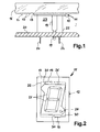
- FIG. 1 shows a sensor element 11 in a side view, which has a sensor surface 12 which a bears flexible contact plate 13 in the manner of a coating.
- the sensor element 11 is provided with the elastic contact plate 13 pressed against the underside 15 of a glass ceramic plate 16.
- the bottom 15 has more or less regular knobs 17, which, however, easily pressed into the contact plate 13 become. This can be flat and essentially rest on the underside 15 without an air gap. 1 the thickness of the contact plate 13 was chosen so that the Penetration depth of the knobs 17 corresponds to approximately 20% of the thickness.
- the sensor element 11 is on a printed circuit board 20 soldered on. Electrical contacts and conductor tracks are omitted here for the sake of clarity.
- the circuit board 20 can both as well as other electrical and / or carry electronic components.
- the housing 22 is a seven-segment display 23 arranged and with solder pins 24 on the Printed circuit board 20 soldered. As can be seen, that's because Sensor element 11 or the sensor surface 12 on the seven-segment display 23, is therefore supported by this. Because of the robust design of housings of such seven-segment displays An arrangement according to FIG. 1 can be advantageous the task of spacers between a circuit board 20 and a cover 16 take over.
- the mainstays 19 essentially have the task of electrical contacting as well as that, the sensor element 11 against to press the display 23.
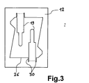
- the top view in FIG. 2 shows the frame-shaped design of the sensor element 11 with the cutout 26, which in the essentially congruent both in the contact plate 13 and is also formed in the sensor surface 12.
- the in Fig. 2nd shown special training of the section 26 is the outer course of the segment bars 27 and the illuminated dot 28 reproduced the display 23.
- the sensor surface 12 lies everywhere on the dashed housing 22 of the display 23 on. In addition, it towers over its sides by a certain amount with the external dimensions of a Rectangle.
- Dotted cuts 30 are shown in the Sensor surface 12 on which the legs 19 in the plane of the drawing are turned into it.
- the neckline can be individual can be adapted to the arrangement of the segment bars.
- FIG 3 shows a plan view of a sensor surface 12 the cutout 26 and the incisions 30 are punched out or have been worked out.
- Advantage arrangement of the non-bent legs 19 within the cutout 26, causing the manufacturing a sensor surface 12 required material surface can be reduced.
- the diametrically opposed Legs 19 offer a good and sufficient attachment of the sensor element 11 down against the housing 22 of the Display 23. It can be seen that the legs 19 are scarce past the housing 22 of the display 23. This can be done under another advantageous for positioning the sensor element 11 when inserted into the circuit board 20.
- a contact plate 13 for example in the embodiment according to FIG. 2, on the sensor surface 12 or the top of the sensor element 11 are glued. Only then are the legs 19 along the dotted line Lines bent over.
- One of the great advantages of the invention is a touch sensitive Create ad.
- the user does not have to trigger sensor surfaces arranged separately from the display, which may first be searched for or assigned have to. Placing your finger on the clearly visible Illuminated display or the cover running over it is for Triggering of a switching process is sufficient, for example as an on / off switch of a cooktop control.
- the size usual seven-segment displays 23 or the included Segment bar 27 enables one to be regarded as sufficient Dimensioning of the actuating surface of the sensor element 11.
- a form of commonly used advertisements of this type indicates a housing with dimensions of approx. 9.5 mm to 13 mm.
- Another big advantage is the flexible coating of the sensor element 11, through which one hitherto with metallic Precise sensor surfaces 12 not yet attainable Adaptation to the underside of a nubbed glass ceramic plate 16 becomes possible.
- Other properties of the flexible material like its internal electrical as well as its inductive resistance due to the conductivity and the volume beneficial to the evaluation of an actuation from or can contribute to the suppression of interference signals.
- a control of the sensor element can be done in different ways Known methods or controls are carried out. As special A circuit arrangement is considered advantageous is contained in DE 297 21 213.
Applications Claiming Priority (2)
| Application Number | Priority Date | Filing Date | Title |
|---|---|---|---|
| DE19907226 | 1999-02-19 | ||
| DE19907226A DE19907226A1 (de) | 1999-02-19 | 1999-02-19 | Berührungsschalter für ein Elektro-Gerät |
Publications (3)
| Publication Number | Publication Date |
|---|---|
| EP1030536A2 true EP1030536A2 (fr) | 2000-08-23 |
| EP1030536A3 EP1030536A3 (fr) | 2001-08-08 |
| EP1030536B1 EP1030536B1 (fr) | 2003-11-12 |
Family
ID=7898209
Family Applications (1)
| Application Number | Title | Priority Date | Filing Date |
|---|---|---|---|
| EP00101346A Expired - Lifetime EP1030536B1 (fr) | 1999-02-19 | 2000-01-24 | Commutateur de proximité destiné à un appareil électro-ménager |
Country Status (7)
| Country | Link |
|---|---|
| US (1) | US6403904B1 (fr) |
| EP (1) | EP1030536B1 (fr) |
| JP (1) | JP2000243171A (fr) |
| AT (1) | ATE254384T1 (fr) |
| DE (2) | DE19907226A1 (fr) |
| ES (1) | ES2209691T3 (fr) |
| PL (1) | PL193982B1 (fr) |
Cited By (13)
| Publication number | Priority date | Publication date | Assignee | Title |
|---|---|---|---|---|
| EP1139695A2 (fr) * | 2000-03-30 | 2001-10-04 | AEG Hausgeräte GmbH | Appareil ménager, en particulier appareil ménager de cuisson |
| EP1257057A1 (fr) * | 2001-05-09 | 2002-11-13 | E.G.O. ELEKTRO-GERÄTEBAU GmbH | Elément capteur pour un commutateur capacitif à effleurement |
| WO2005043760A1 (fr) * | 2003-11-03 | 2005-05-12 | E.G.O. Control Systems Gmbh | Dispositif de commande pour commander un appareil electrique au moyen d'un commutateur tactile |
| DE10352714A1 (de) * | 2003-11-05 | 2005-07-07 | E.G.O. Elektro-Gerätebau GmbH | Bedieneinrichtung |
| DE102004043571A1 (de) * | 2004-09-09 | 2006-03-30 | Diehl Ako Stiftung & Co. Kg | Siebensegmentanzeige |
| DE102009021033A1 (de) | 2009-05-07 | 2010-09-16 | E.G.O. Elektro-Gerätebau GmbH | Bedieneinrichtung und Verfahren zur Herstellung einer Bedieneinrichtung |
| EP2280484A1 (fr) | 2009-07-28 | 2011-02-02 | E.G.O. Elektro-Gerätebau GmbH | Dispositif à élément de détection |
| EP2662981A1 (fr) * | 2012-05-07 | 2013-11-13 | Diehl AKO Stiftung & Co. KG | Commutateur de proximité et/ou de contact capacitive avec électrode flottante |
| FR3002661A1 (fr) * | 2013-02-28 | 2014-08-29 | Atlantic Industrie Sas | Systeme de detection de toucher par effet capacitif pour dispositif electronique |
| EP2557363A3 (fr) * | 2011-08-08 | 2015-03-11 | Vestel Beyaz Esya Sanayi Ve Ticaret A.S. | Appareil ménager électronique avec un capteur et son support |
| EP2937998A1 (fr) * | 2014-04-25 | 2015-10-28 | Home Control Singapore Pte. Ltd. | Fournir une détection capacitive à un bouton poussoir |
| DE102016216035A1 (de) | 2016-08-25 | 2018-03-01 | E.G.O. Elektro-Gerätebau GmbH | Elektrogerät, Anordnung eines solchen Elektrogeräts mit einer Blende und Verfahren zur Herstellung einer solchen Anordnung |
| EP3537049A1 (fr) | 2018-03-09 | 2019-09-11 | E.G.O. ELEKTRO-GERÄTEBAU GmbH | Procédé de représentation d'un affichage sur un champ de cuisson et champ de cuisson |
Families Citing this family (28)
| Publication number | Priority date | Publication date | Assignee | Title |
|---|---|---|---|---|
| US6756703B2 (en) * | 2002-02-27 | 2004-06-29 | Chi Che Chang | Trigger switch module |
| DE10259297B4 (de) * | 2002-05-07 | 2006-11-16 | Schott Ag | Beleuchtungseinrichtung für Schaltflächen |
| EP1376872B1 (fr) | 2002-05-07 | 2007-10-10 | Schott Ag | Dispositif d'éclairage pour des écrans sensibles à toucher |
| DE20215326U1 (de) * | 2002-10-04 | 2004-02-26 | Diehl Ako Stiftung & Co. Kg | Bedieneinrichtung für ein Gargerät |
| DE10314591B4 (de) * | 2003-03-31 | 2014-10-02 | BSH Bosch und Siemens Hausgeräte GmbH | Berührungsschalter |
| DE10320548B4 (de) * | 2003-05-07 | 2005-02-24 | Schott Ag | Berührungsschalteinrichtung |
| DE102004011734A1 (de) * | 2004-03-04 | 2005-09-22 | E.G.O. Elektro-Gerätebau GmbH | Elektrisches Haushaltsgerät |
| DE102004019304A1 (de) * | 2004-04-15 | 2005-11-03 | E.G.O. Control Systems Gmbh | Bedieneinrichtung mit einem Berührungsschalter |
| DE102005008791A1 (de) * | 2005-02-25 | 2006-09-07 | Siemens Ag | Betätigungseinrichtung in einem Kraftfahrzeug, angebunden an ein System zur Bedienererkennung |
| ES2335120T3 (es) * | 2005-04-25 | 2010-03-22 | Electrolux Home Products Corporation N.V. | Panel de control con conmutadores tactiles capacitivos iluminados. |
| DE102006005677B4 (de) * | 2006-01-30 | 2015-12-31 | E.G.O. Elektro-Gerätebau GmbH | Kochfeld |
| EP2019606B1 (fr) * | 2006-05-01 | 2020-01-08 | Linak A/S | Table réglable électriquement |
| DE102006022965A1 (de) * | 2006-05-12 | 2007-11-15 | E.G.O. Elektro-Gerätebau GmbH | Bedieneinheit für Haushaltsgeräte |
| DE102006039133A1 (de) * | 2006-08-21 | 2008-03-06 | BSH Bosch und Siemens Hausgeräte GmbH | Bedieneinrichtung für ein Haushaltsgerät mit zumindest einer kapazitiven Sensortaste |
| EP2048781B1 (fr) * | 2007-10-08 | 2018-06-13 | Whirlpool Corporation | Interrupteur tactile pour appareils électriques et appareil électrique doté d'un tel interrupteur |
| PL2048779T3 (pl) * | 2007-10-08 | 2012-05-31 | Whirlpool Co | Pojemnościowy przełącznik dotykowy i urządzenie gospodarstwa domowego wyposażone w taki przełącznik |
| EP2417703A2 (fr) * | 2009-04-09 | 2012-02-15 | TouchSensor Technologies, L.L.C. | Electrode tactile intégrée et masque de rétroéclairage |
| DE102009033538A1 (de) | 2009-07-09 | 2011-01-13 | E.G.O. Elektro-Gerätebau GmbH | Bedieneinrichtung für ein Elektrogerät |
| US8730185B2 (en) * | 2009-12-23 | 2014-05-20 | Electrolux Home Products, Inc. | User interface with annular touch sensor array |
| US8570284B2 (en) * | 2009-12-23 | 2013-10-29 | Electrolux Home Products, Inc. | Annular bar graph and multi-segment display |
| US9100022B2 (en) | 2012-03-23 | 2015-08-04 | Touchsensor Technologies, Llc | Touch responsive user interface with backlit graphics |
| DE102013213036B9 (de) | 2013-07-03 | 2020-03-05 | E.G.O. Elektro-Gerätebau GmbH | Bedienelement, Bedieneinrichtung und Verfahren zur Herstellung eines Bedienelements |
| DE102013214162B4 (de) * | 2013-07-18 | 2019-05-09 | E.G.O. Elektro-Gerätebau GmbH | Bedienteil für eine Bedieneinrichtung und Bedieneinrichtung |
| CN104867415A (zh) * | 2015-05-30 | 2015-08-26 | 中山市晶艺光电科技有限公司 | 一种具有触摸感应结构的壳体和一种led数码显示器 |
| EP3121965B1 (fr) * | 2015-07-21 | 2020-07-08 | E.G.O. ELEKTRO-GERÄTEBAU GmbH | Dispositif de commande d'appareil electrique et appareil electrique et procede de fabrication d'un film support |
| CN105743482A (zh) * | 2016-02-18 | 2016-07-06 | 陈策 | 一种智能触摸墙壁开关 |
| EP3522680B1 (fr) * | 2018-02-02 | 2021-07-21 | Electrolux Appliances Aktiebolag | Interface utilisateur pour appareil domestique |
| TWI690840B (zh) * | 2019-04-19 | 2020-04-11 | 展躍光電科技股份有限公司 | 觸控顯示裝置與觸控顯示模組 |
Citations (4)
| Publication number | Priority date | Publication date | Assignee | Title |
|---|---|---|---|---|
| EP0841752A2 (fr) * | 1996-11-09 | 1998-05-13 | DIEHL GMBH & CO. | Ensemble de commande, notamment pour un four de cuisson ou de boulanger |
| EP0859468A1 (fr) * | 1997-02-17 | 1998-08-19 | E.G.O. ELEKTRO-GERÄTEBAU GmbH | Circuit pour un élément capteur |
| DE19712137A1 (de) * | 1997-03-22 | 1998-09-24 | Aeg Hausgeraete Gmbh | Verfahren und Vorrichtung zum Einstellen eines Betriebszustandes eines Haushaltsgerätes mit einem wenigstens teilweise metallischen Bedienelement |
| DE19802479A1 (de) * | 1998-01-23 | 1999-07-29 | Sechting Karl Heinz | Sensortastatur mit Rückmeldung |
Family Cites Families (13)
| Publication number | Priority date | Publication date | Assignee | Title |
|---|---|---|---|---|
| DE3119495A1 (de) * | 1980-05-27 | 1982-02-25 | Playmont AG, St. Gallen | "annaeherungs-schalter" |
| US4855550A (en) * | 1988-01-04 | 1989-08-08 | General Electric Company | White touch pads for capacitive touch control panels |
| US4894493A (en) * | 1988-11-04 | 1990-01-16 | General Electric Company | Membrane touch control panel assembly for an appliance with a glass control panel |
| US5235217A (en) * | 1991-07-24 | 1993-08-10 | Isb Ltd. | Capacitive press control actuation system |
| US5572205A (en) * | 1993-03-29 | 1996-11-05 | Donnelly Technology, Inc. | Touch control system |
| US5491314A (en) * | 1994-08-11 | 1996-02-13 | Whirlpool Corporation | Flat high temperature membrane switch display window |
| US5721666A (en) * | 1995-02-28 | 1998-02-24 | Master Molded Products Corporation | Device panel with in-molded applique |
| JP3198046B2 (ja) * | 1996-03-14 | 2001-08-13 | 株式会社リコー | 入力タッチパネル付き液晶表示装置 |
| ES2174342T3 (es) * | 1997-02-17 | 2002-11-01 | Ego Elektro Geraetebau Gmbh | Interruptor por tacto con tecla sensorial. |
| DE19706167A1 (de) * | 1997-02-17 | 1998-08-20 | Ego Elektro Geraetebau Gmbh | Schaltungsanordnung für ein Sensorelement |
| DE19706168A1 (de) * | 1997-02-17 | 1998-08-20 | Ego Elektro Geraetebau Gmbh | Berührungsschalter mit Sensortaste |
| DE19714195A1 (de) * | 1997-04-07 | 1998-10-08 | Aeg Hausgeraete Gmbh | Verfahren und Vorrichtung zum Einstellen eines Betriebszustandes eines Haushaltsgerätes an einem mit einer Anzeige versehenen Bedienelement |
| US6137072A (en) * | 1999-05-26 | 2000-10-24 | Ferro Corporation | Control panel |
-
1999
- 1999-02-19 DE DE19907226A patent/DE19907226A1/de not_active Withdrawn
-
2000
- 2000-01-24 AT AT00101346T patent/ATE254384T1/de not_active IP Right Cessation
- 2000-01-24 EP EP00101346A patent/EP1030536B1/fr not_active Expired - Lifetime
- 2000-01-24 DE DE50004384T patent/DE50004384D1/de not_active Expired - Lifetime
- 2000-01-24 ES ES00101346T patent/ES2209691T3/es not_active Expired - Lifetime
- 2000-02-14 PL PL338410A patent/PL193982B1/pl unknown
- 2000-02-18 US US09/506,994 patent/US6403904B1/en not_active Expired - Lifetime
- 2000-02-18 JP JP2000041201A patent/JP2000243171A/ja active Pending
Patent Citations (4)
| Publication number | Priority date | Publication date | Assignee | Title |
|---|---|---|---|---|
| EP0841752A2 (fr) * | 1996-11-09 | 1998-05-13 | DIEHL GMBH & CO. | Ensemble de commande, notamment pour un four de cuisson ou de boulanger |
| EP0859468A1 (fr) * | 1997-02-17 | 1998-08-19 | E.G.O. ELEKTRO-GERÄTEBAU GmbH | Circuit pour un élément capteur |
| DE19712137A1 (de) * | 1997-03-22 | 1998-09-24 | Aeg Hausgeraete Gmbh | Verfahren und Vorrichtung zum Einstellen eines Betriebszustandes eines Haushaltsgerätes mit einem wenigstens teilweise metallischen Bedienelement |
| DE19802479A1 (de) * | 1998-01-23 | 1999-07-29 | Sechting Karl Heinz | Sensortastatur mit Rückmeldung |
Cited By (20)
| Publication number | Priority date | Publication date | Assignee | Title |
|---|---|---|---|---|
| EP1139695A3 (fr) * | 2000-03-30 | 2003-12-03 | AEG Hausgeräte GmbH | Appareil ménager, en particulier appareil ménager de cuisson |
| EP1139695A2 (fr) * | 2000-03-30 | 2001-10-04 | AEG Hausgeräte GmbH | Appareil ménager, en particulier appareil ménager de cuisson |
| EP1257057A1 (fr) * | 2001-05-09 | 2002-11-13 | E.G.O. ELEKTRO-GERÄTEBAU GmbH | Elément capteur pour un commutateur capacitif à effleurement |
| WO2005043760A1 (fr) * | 2003-11-03 | 2005-05-12 | E.G.O. Control Systems Gmbh | Dispositif de commande pour commander un appareil electrique au moyen d'un commutateur tactile |
| DE10352681A1 (de) * | 2003-11-03 | 2005-06-02 | E.G.O. Control Systems Gmbh & Co. Kg | Bedieneinrichtung zur Bedienung eines Elektrogeräts mit einem Berührungsschalter |
| DE10352714A1 (de) * | 2003-11-05 | 2005-07-07 | E.G.O. Elektro-Gerätebau GmbH | Bedieneinrichtung |
| DE102004043571A1 (de) * | 2004-09-09 | 2006-03-30 | Diehl Ako Stiftung & Co. Kg | Siebensegmentanzeige |
| DE102009021033A1 (de) | 2009-05-07 | 2010-09-16 | E.G.O. Elektro-Gerätebau GmbH | Bedieneinrichtung und Verfahren zur Herstellung einer Bedieneinrichtung |
| EP2280484A1 (fr) | 2009-07-28 | 2011-02-02 | E.G.O. Elektro-Gerätebau GmbH | Dispositif à élément de détection |
| DE102009036162A1 (de) | 2009-07-28 | 2011-02-03 | E.G.O. Elektro-Gerätebau GmbH | Sensorelementeinrichtung |
| EP2557363A3 (fr) * | 2011-08-08 | 2015-03-11 | Vestel Beyaz Esya Sanayi Ve Ticaret A.S. | Appareil ménager électronique avec un capteur et son support |
| EP2662981A1 (fr) * | 2012-05-07 | 2013-11-13 | Diehl AKO Stiftung & Co. KG | Commutateur de proximité et/ou de contact capacitive avec électrode flottante |
| US9973190B2 (en) | 2012-05-07 | 2018-05-15 | Diehl Ako Stiftung & Co. Kg | Capacitive proximity and/or contact switch |
| EP2773043A1 (fr) | 2013-02-28 | 2014-09-03 | Atlantic Industrie | Systeme de detection de toucher par effet capacitif pour dispositif electronique |
| FR3002661A1 (fr) * | 2013-02-28 | 2014-08-29 | Atlantic Industrie Sas | Systeme de detection de toucher par effet capacitif pour dispositif electronique |
| RU2615064C2 (ru) * | 2013-02-28 | 2017-04-03 | АТЛАНТИК ИНДУСТРИ, Франция | Система определения прикосновений с использованием емкостного эффекта для электронных устройств |
| EP2937998A1 (fr) * | 2014-04-25 | 2015-10-28 | Home Control Singapore Pte. Ltd. | Fournir une détection capacitive à un bouton poussoir |
| DE102016216035A1 (de) | 2016-08-25 | 2018-03-01 | E.G.O. Elektro-Gerätebau GmbH | Elektrogerät, Anordnung eines solchen Elektrogeräts mit einer Blende und Verfahren zur Herstellung einer solchen Anordnung |
| EP3537049A1 (fr) | 2018-03-09 | 2019-09-11 | E.G.O. ELEKTRO-GERÄTEBAU GmbH | Procédé de représentation d'un affichage sur un champ de cuisson et champ de cuisson |
| DE102018203607A1 (de) | 2018-03-09 | 2019-09-12 | E.G.O. Elektro-Gerätebau GmbH | Verfahren zur Darstellung einer Anzeige an einem Kochfeld und Kochfeld |
Also Published As
| Publication number | Publication date |
|---|---|
| EP1030536A3 (fr) | 2001-08-08 |
| DE50004384D1 (de) | 2003-12-18 |
| PL193982B1 (pl) | 2007-04-30 |
| JP2000243171A (ja) | 2000-09-08 |
| US6403904B1 (en) | 2002-06-11 |
| ATE254384T1 (de) | 2003-11-15 |
| EP1030536B1 (fr) | 2003-11-12 |
| PL338410A1 (en) | 2000-08-28 |
| DE19907226A1 (de) | 2000-08-24 |
| ES2209691T3 (es) | 2004-07-01 |
Similar Documents
| Publication | Publication Date | Title |
|---|---|---|
| EP1030536B1 (fr) | Commutateur de proximité destiné à un appareil électro-ménager | |
| EP2853027B1 (fr) | Agencement avec dispositif a element capteur sur un support de composants pour un commutateur tactile capacitif d'un dispositif de commande, dispositif de commande et plaque de cuisson avec un tel agencement | |
| EP1257057B1 (fr) | Elément capteur pour un commutateur capacitif à effleurement | |
| EP1731841B1 (fr) | Plaque de cuisson avec dispositif de commande | |
| EP1760886B1 (fr) | Dispositif de capteur | |
| DE2319042A1 (de) | Elektrischer kontaktschalter, insbesondere gewoehnlich offener kontaktschalter | |
| DE20119700U1 (de) | Sensorvorrichtung | |
| DE3222237A1 (de) | Kippschalter | |
| DE102014114170B4 (de) | Bedienelement mit Schaltmatte | |
| WO2008022866A1 (fr) | plaque de recouvrement pour sonde capacitive d'approche et/ou de contact | |
| DE102009021033A1 (de) | Bedieneinrichtung und Verfahren zur Herstellung einer Bedieneinrichtung | |
| DE102011006021A1 (de) | Bedieneinrichtung für ein Elektrogerät | |
| DE2907697C2 (de) | Tastatur für ein elektronisches Gerät | |
| DE10110759B4 (de) | Elektrischer Installationsschalter | |
| DE3619035A1 (de) | Durch beruehrung zu betaetigende durchsichtige eingabeeinrichtung zum betrieb in verbindung mit einer anzeigeeinrichtung | |
| DE2647922A1 (de) | Tastenbrett mit drucktasten zur alphanumerischen steuerung fuer eine elektrische oder elektronische maschine | |
| DE2910001C2 (de) | Äußere Betätigungsvorrichtung für eine elektronische Uhr | |
| DE102013003659A1 (de) | Beleuchteter kapazitiver Taster | |
| DE2439697B2 (de) | Druckschalter | |
| DE112016003061B4 (de) | Eingabevorrichtung | |
| DE102008021943A1 (de) | Elektrogerät mit großflächiger, transparenter Platte sowie kapazitiver Bedieneinrichtung | |
| DE202015102661U1 (de) | Gefederter Taster | |
| DE19616917A1 (de) | Betätigungsvorrichtung für elektrische Drucktastenschalter | |
| DE10209079A1 (de) | Folientastatur | |
| DE102015216634A1 (de) | Anzeigeeinrichtung für ein Elektrogerät und Elektrogerät |
Legal Events
| Date | Code | Title | Description |
|---|---|---|---|
| PUAI | Public reference made under article 153(3) epc to a published international application that has entered the european phase |
Free format text: ORIGINAL CODE: 0009012 |
|
| AK | Designated contracting states |
Kind code of ref document: A2 Designated state(s): AT BE CH CY DE DK ES FI FR GB GR IE IT LI LU MC NL PT SE |
|
| AX | Request for extension of the european patent |
Free format text: AL;LT;LV;MK;RO;SI |
|
| PUAL | Search report despatched |
Free format text: ORIGINAL CODE: 0009013 |
|
| AK | Designated contracting states |
Kind code of ref document: A3 Designated state(s): AT BE CH CY DE DK ES FI FR GB GR IE IT LI LU MC NL PT SE |
|
| AX | Request for extension of the european patent |
Free format text: AL;LT;LV;MK;RO;SI |
|
| 17P | Request for examination filed |
Effective date: 20020112 |
|
| AKX | Designation fees paid |
Free format text: AT BE CH CY DE DK ES FI FR GB GR IE IT LI LU MC NL PT SE |
|
| AXX | Extension fees paid |
Free format text: SI PAYMENT 20020112 |
|
| GRAH | Despatch of communication of intention to grant a patent |
Free format text: ORIGINAL CODE: EPIDOS IGRA |
|
| GRAS | Grant fee paid |
Free format text: ORIGINAL CODE: EPIDOSNIGR3 |
|
| GRAA | (expected) grant |
Free format text: ORIGINAL CODE: 0009210 |
|
| STAA | Information on the status of an ep patent application or granted ep patent |
Free format text: STATUS: THE PATENT HAS BEEN GRANTED |
|
| AK | Designated contracting states |
Kind code of ref document: B1 Designated state(s): AT BE CH CY DE DK ES FI FR GB GR IE IT LI LU MC NL PT SE |
|
| AX | Request for extension of the european patent |
Extension state: SI |
|
| PG25 | Lapsed in a contracting state [announced via postgrant information from national office to epo] |
Ref country code: IE Free format text: LAPSE BECAUSE OF FAILURE TO SUBMIT A TRANSLATION OF THE DESCRIPTION OR TO PAY THE FEE WITHIN THE PRESCRIBED TIME-LIMIT Effective date: 20031112 Ref country code: FI Free format text: LAPSE BECAUSE OF FAILURE TO SUBMIT A TRANSLATION OF THE DESCRIPTION OR TO PAY THE FEE WITHIN THE PRESCRIBED TIME-LIMIT Effective date: 20031112 Ref country code: CY Free format text: LAPSE BECAUSE OF FAILURE TO SUBMIT A TRANSLATION OF THE DESCRIPTION OR TO PAY THE FEE WITHIN THE PRESCRIBED TIME-LIMIT Effective date: 20031112 Ref country code: NL Free format text: LAPSE BECAUSE OF FAILURE TO SUBMIT A TRANSLATION OF THE DESCRIPTION OR TO PAY THE FEE WITHIN THE PRESCRIBED TIME-LIMIT Effective date: 20031112 |
|
| REG | Reference to a national code |
Ref country code: GB Ref legal event code: FG4D Free format text: NOT ENGLISH |
|
| REG | Reference to a national code |
Ref country code: CH Ref legal event code: EP |
|
| REF | Corresponds to: |
Ref document number: 50004384 Country of ref document: DE Date of ref document: 20031218 Kind code of ref document: P |
|
| REG | Reference to a national code |
Ref country code: SE Ref legal event code: TRGR |
|
| REG | Reference to a national code |
Ref country code: IE Ref legal event code: FG4D Free format text: GERMAN |
|
| GBT | Gb: translation of ep patent filed (gb section 77(6)(a)/1977) |
Effective date: 20031224 |
|
| PG25 | Lapsed in a contracting state [announced via postgrant information from national office to epo] |
Ref country code: AT Free format text: LAPSE BECAUSE OF NON-PAYMENT OF DUE FEES Effective date: 20040124 Ref country code: LU Free format text: LAPSE BECAUSE OF NON-PAYMENT OF DUE FEES Effective date: 20040124 |
|
| PG25 | Lapsed in a contracting state [announced via postgrant information from national office to epo] |
Ref country code: LI Free format text: LAPSE BECAUSE OF NON-PAYMENT OF DUE FEES Effective date: 20040131 Ref country code: CH Free format text: LAPSE BECAUSE OF NON-PAYMENT OF DUE FEES Effective date: 20040131 Ref country code: MC Free format text: LAPSE BECAUSE OF NON-PAYMENT OF DUE FEES Effective date: 20040131 Ref country code: BE Free format text: LAPSE BECAUSE OF NON-PAYMENT OF DUE FEES Effective date: 20040131 |
|
| PG25 | Lapsed in a contracting state [announced via postgrant information from national office to epo] |
Ref country code: GR Free format text: LAPSE BECAUSE OF FAILURE TO SUBMIT A TRANSLATION OF THE DESCRIPTION OR TO PAY THE FEE WITHIN THE PRESCRIBED TIME-LIMIT Effective date: 20040212 Ref country code: DK Free format text: LAPSE BECAUSE OF FAILURE TO SUBMIT A TRANSLATION OF THE DESCRIPTION OR TO PAY THE FEE WITHIN THE PRESCRIBED TIME-LIMIT Effective date: 20040212 |
|
| NLV1 | Nl: lapsed or annulled due to failure to fulfill the requirements of art. 29p and 29m of the patents act | ||
| REG | Reference to a national code |
Ref country code: IE Ref legal event code: FD4D |
|
| REG | Reference to a national code |
Ref country code: ES Ref legal event code: FG2A Ref document number: 2209691 Country of ref document: ES Kind code of ref document: T3 |
|
| BERE | Be: lapsed |
Owner name: *EGO ELEKTRO-GERATEBAU G.M.B.H. Effective date: 20040131 |
|
| PLBI | Opposition filed |
Free format text: ORIGINAL CODE: 0009260 |
|
| ET | Fr: translation filed | ||
| PLAX | Notice of opposition and request to file observation + time limit sent |
Free format text: ORIGINAL CODE: EPIDOSNOBS2 |
|
| REG | Reference to a national code |
Ref country code: CH Ref legal event code: PL |
|
| 26 | Opposition filed |
Opponent name: BSH BOSCH UND SIEMENS HAUSGERAETE GMBH Effective date: 20040811 |
|
| PLAN | Information deleted related to communication of a notice of opposition and request to file observations + time limit |
Free format text: ORIGINAL CODE: EPIDOSDOBS2 |
|
| PLBG | Opposition deemed not to have been filed |
Free format text: ORIGINAL CODE: 0009274 |
|
| 26D | Opposition deemed not to have been filed |
Opponent name: BSH BOSCH UND SIEMENS HAUSGERAETE GMBH Effective date: 20041228 |
|
| PG25 | Lapsed in a contracting state [announced via postgrant information from national office to epo] |
Ref country code: PT Free format text: LAPSE BECAUSE OF NON-PAYMENT OF DUE FEES Effective date: 20040412 |
|
| PGFP | Annual fee paid to national office [announced via postgrant information from national office to epo] |
Ref country code: SE Payment date: 20140123 Year of fee payment: 15 |
|
| REG | Reference to a national code |
Ref country code: SE Ref legal event code: EUG |
|
| PG25 | Lapsed in a contracting state [announced via postgrant information from national office to epo] |
Ref country code: SE Free format text: LAPSE BECAUSE OF NON-PAYMENT OF DUE FEES Effective date: 20150125 |
|
| REG | Reference to a national code |
Ref country code: FR Ref legal event code: PLFP Year of fee payment: 17 |
|
| REG | Reference to a national code |
Ref country code: FR Ref legal event code: PLFP Year of fee payment: 18 |
|
| REG | Reference to a national code |
Ref country code: FR Ref legal event code: PLFP Year of fee payment: 19 |
|
| PGFP | Annual fee paid to national office [announced via postgrant information from national office to epo] |
Ref country code: ES Payment date: 20190215 Year of fee payment: 20 Ref country code: IT Payment date: 20190121 Year of fee payment: 20 Ref country code: GB Payment date: 20190124 Year of fee payment: 20 Ref country code: FR Payment date: 20190123 Year of fee payment: 20 Ref country code: DE Payment date: 20190124 Year of fee payment: 20 |
|
| REG | Reference to a national code |
Ref country code: DE Ref legal event code: R071 Ref document number: 50004384 Country of ref document: DE |
|
| REG | Reference to a national code |
Ref country code: GB Ref legal event code: PE20 Expiry date: 20200123 |
|
| PG25 | Lapsed in a contracting state [announced via postgrant information from national office to epo] |
Ref country code: GB Free format text: LAPSE BECAUSE OF EXPIRATION OF PROTECTION Effective date: 20200123 |
|
| REG | Reference to a national code |
Ref country code: ES Ref legal event code: FD2A Effective date: 20200721 |
|
| PG25 | Lapsed in a contracting state [announced via postgrant information from national office to epo] |
Ref country code: ES Free format text: LAPSE BECAUSE OF EXPIRATION OF PROTECTION Effective date: 20200125 |