EP1029796B1 - Kunststoffbehälter und Verfahren sowie Vorrichtung zu dessen Herstellung und Handhabung - Google Patents
Kunststoffbehälter und Verfahren sowie Vorrichtung zu dessen Herstellung und Handhabung Download PDFInfo
- Publication number
- EP1029796B1 EP1029796B1 EP00102253A EP00102253A EP1029796B1 EP 1029796 B1 EP1029796 B1 EP 1029796B1 EP 00102253 A EP00102253 A EP 00102253A EP 00102253 A EP00102253 A EP 00102253A EP 1029796 B1 EP1029796 B1 EP 1029796B1
- Authority
- EP
- European Patent Office
- Prior art keywords
- container
- handle
- lid
- recess
- safety element
- Prior art date
- Legal status (The legal status is an assumption and is not a legal conclusion. Google has not performed a legal analysis and makes no representation as to the accuracy of the status listed.)
- Expired - Lifetime
Links
- 238000004519 manufacturing process Methods 0.000 title claims description 13
- 238000000034 method Methods 0.000 title claims description 11
- 239000004033 plastic Substances 0.000 title claims description 8
- 238000007789 sealing Methods 0.000 claims description 30
- 238000002347 injection Methods 0.000 claims description 20
- 239000007924 injection Substances 0.000 claims description 20
- 210000001331 nose Anatomy 0.000 claims description 8
- 239000000463 material Substances 0.000 claims description 3
- 239000003086 colorant Substances 0.000 claims description 2
- 230000002093 peripheral effect Effects 0.000 description 6
- 238000001746 injection moulding Methods 0.000 description 5
- 210000003128 head Anatomy 0.000 description 3
- 238000007639 printing Methods 0.000 description 2
- 238000005507 spraying Methods 0.000 description 2
- 244000056139 Brassica cretica Species 0.000 description 1
- 235000003351 Brassica cretica Nutrition 0.000 description 1
- 235000003343 Brassica rupestris Nutrition 0.000 description 1
- 240000008067 Cucumis sativus Species 0.000 description 1
- 235000010799 Cucumis sativus var sativus Nutrition 0.000 description 1
- 239000000853 adhesive Substances 0.000 description 1
- 230000001070 adhesive effect Effects 0.000 description 1
- 239000011324 bead Substances 0.000 description 1
- 230000015572 biosynthetic process Effects 0.000 description 1
- QKSKPIVNLNLAAV-UHFFFAOYSA-N bis(2-chloroethyl) sulfide Chemical compound ClCCSCCCl QKSKPIVNLNLAAV-UHFFFAOYSA-N 0.000 description 1
- 229910003460 diamond Inorganic materials 0.000 description 1
- 239000010432 diamond Substances 0.000 description 1
- 238000006073 displacement reaction Methods 0.000 description 1
- 235000013305 food Nutrition 0.000 description 1
- 235000015243 ice cream Nutrition 0.000 description 1
- 235000015094 jam Nutrition 0.000 description 1
- 238000002372 labelling Methods 0.000 description 1
- 239000007788 liquid Substances 0.000 description 1
- 230000007257 malfunction Effects 0.000 description 1
- 239000002991 molded plastic Substances 0.000 description 1
- 235000010460 mustard Nutrition 0.000 description 1
- 238000007493 shaping process Methods 0.000 description 1
- 125000006850 spacer group Chemical group 0.000 description 1
- 239000007921 spray Substances 0.000 description 1
- 230000006641 stabilisation Effects 0.000 description 1
- 238000011105 stabilization Methods 0.000 description 1
- 230000007704 transition Effects 0.000 description 1
Images






Classifications
-
- B—PERFORMING OPERATIONS; TRANSPORTING
- B65—CONVEYING; PACKING; STORING; HANDLING THIN OR FILAMENTARY MATERIAL
- B65D—CONTAINERS FOR STORAGE OR TRANSPORT OF ARTICLES OR MATERIALS, e.g. BAGS, BARRELS, BOTTLES, BOXES, CANS, CARTONS, CRATES, DRUMS, JARS, TANKS, HOPPERS, FORWARDING CONTAINERS; ACCESSORIES, CLOSURES, OR FITTINGS THEREFOR; PACKAGING ELEMENTS; PACKAGES
- B65D21/00—Nestable, stackable or joinable containers; Containers of variable capacity
- B65D21/02—Containers specially shaped, or provided with fittings or attachments, to facilitate nesting, stacking, or joining together
- B65D21/0233—Nestable containers
-
- B—PERFORMING OPERATIONS; TRANSPORTING
- B29—WORKING OF PLASTICS; WORKING OF SUBSTANCES IN A PLASTIC STATE IN GENERAL
- B29C—SHAPING OR JOINING OF PLASTICS; SHAPING OF MATERIAL IN A PLASTIC STATE, NOT OTHERWISE PROVIDED FOR; AFTER-TREATMENT OF THE SHAPED PRODUCTS, e.g. REPAIRING
- B29C45/00—Injection moulding, i.e. forcing the required volume of moulding material through a nozzle into a closed mould; Apparatus therefor
- B29C45/0017—Injection moulding, i.e. forcing the required volume of moulding material through a nozzle into a closed mould; Apparatus therefor moulding interconnected elements which are movable with respect to one another, e.g. chains or hinges
-
- B—PERFORMING OPERATIONS; TRANSPORTING
- B29—WORKING OF PLASTICS; WORKING OF SUBSTANCES IN A PLASTIC STATE IN GENERAL
- B29C—SHAPING OR JOINING OF PLASTICS; SHAPING OF MATERIAL IN A PLASTIC STATE, NOT OTHERWISE PROVIDED FOR; AFTER-TREATMENT OF THE SHAPED PRODUCTS, e.g. REPAIRING
- B29C45/00—Injection moulding, i.e. forcing the required volume of moulding material through a nozzle into a closed mould; Apparatus therefor
- B29C45/0053—Injection moulding, i.e. forcing the required volume of moulding material through a nozzle into a closed mould; Apparatus therefor combined with a final operation, e.g. shaping
- B29C45/006—Joining parts moulded in separate cavities
-
- B—PERFORMING OPERATIONS; TRANSPORTING
- B65—CONVEYING; PACKING; STORING; HANDLING THIN OR FILAMENTARY MATERIAL
- B65D—CONTAINERS FOR STORAGE OR TRANSPORT OF ARTICLES OR MATERIALS, e.g. BAGS, BARRELS, BOTTLES, BOXES, CANS, CARTONS, CRATES, DRUMS, JARS, TANKS, HOPPERS, FORWARDING CONTAINERS; ACCESSORIES, CLOSURES, OR FITTINGS THEREFOR; PACKAGING ELEMENTS; PACKAGES
- B65D25/00—Details of other kinds or types of rigid or semi-rigid containers
- B65D25/28—Handles
- B65D25/32—Bail handles, i.e. pivoted rigid handles of generally semi-circular shape with pivot points on two opposed sides or wall parts of the conainter
-
- B—PERFORMING OPERATIONS; TRANSPORTING
- B65—CONVEYING; PACKING; STORING; HANDLING THIN OR FILAMENTARY MATERIAL
- B65D—CONTAINERS FOR STORAGE OR TRANSPORT OF ARTICLES OR MATERIALS, e.g. BAGS, BARRELS, BOTTLES, BOXES, CANS, CARTONS, CRATES, DRUMS, JARS, TANKS, HOPPERS, FORWARDING CONTAINERS; ACCESSORIES, CLOSURES, OR FITTINGS THEREFOR; PACKAGING ELEMENTS; PACKAGES
- B65D43/00—Lids or covers for rigid or semi-rigid containers
- B65D43/02—Removable lids or covers
- B65D43/0202—Removable lids or covers without integral tamper element
- B65D43/0204—Removable lids or covers without integral tamper element secured by snapping over beads or projections
- B65D43/0212—Removable lids or covers without integral tamper element secured by snapping over beads or projections only on the outside, or a part turned to the outside, of the mouth
-
- B—PERFORMING OPERATIONS; TRANSPORTING
- B29—WORKING OF PLASTICS; WORKING OF SUBSTANCES IN A PLASTIC STATE IN GENERAL
- B29C—SHAPING OR JOINING OF PLASTICS; SHAPING OF MATERIAL IN A PLASTIC STATE, NOT OTHERWISE PROVIDED FOR; AFTER-TREATMENT OF THE SHAPED PRODUCTS, e.g. REPAIRING
- B29C45/00—Injection moulding, i.e. forcing the required volume of moulding material through a nozzle into a closed mould; Apparatus therefor
- B29C45/0017—Injection moulding, i.e. forcing the required volume of moulding material through a nozzle into a closed mould; Apparatus therefor moulding interconnected elements which are movable with respect to one another, e.g. chains or hinges
- B29C2045/0018—Injection moulding, i.e. forcing the required volume of moulding material through a nozzle into a closed mould; Apparatus therefor moulding interconnected elements which are movable with respect to one another, e.g. chains or hinges moulding containers with handle, e.g. buckets
-
- B—PERFORMING OPERATIONS; TRANSPORTING
- B29—WORKING OF PLASTICS; WORKING OF SUBSTANCES IN A PLASTIC STATE IN GENERAL
- B29C—SHAPING OR JOINING OF PLASTICS; SHAPING OF MATERIAL IN A PLASTIC STATE, NOT OTHERWISE PROVIDED FOR; AFTER-TREATMENT OF THE SHAPED PRODUCTS, e.g. REPAIRING
- B29C45/00—Injection moulding, i.e. forcing the required volume of moulding material through a nozzle into a closed mould; Apparatus therefor
- B29C45/0053—Injection moulding, i.e. forcing the required volume of moulding material through a nozzle into a closed mould; Apparatus therefor combined with a final operation, e.g. shaping
- B29C45/006—Joining parts moulded in separate cavities
- B29C2045/007—Joining parts moulded in separate cavities assembling a container and a handle
-
- B—PERFORMING OPERATIONS; TRANSPORTING
- B65—CONVEYING; PACKING; STORING; HANDLING THIN OR FILAMENTARY MATERIAL
- B65D—CONTAINERS FOR STORAGE OR TRANSPORT OF ARTICLES OR MATERIALS, e.g. BAGS, BARRELS, BOTTLES, BOXES, CANS, CARTONS, CRATES, DRUMS, JARS, TANKS, HOPPERS, FORWARDING CONTAINERS; ACCESSORIES, CLOSURES, OR FITTINGS THEREFOR; PACKAGING ELEMENTS; PACKAGES
- B65D2401/00—Tamper-indicating means
- B65D2401/10—Tearable part of the container
-
- B—PERFORMING OPERATIONS; TRANSPORTING
- B65—CONVEYING; PACKING; STORING; HANDLING THIN OR FILAMENTARY MATERIAL
- B65D—CONTAINERS FOR STORAGE OR TRANSPORT OF ARTICLES OR MATERIALS, e.g. BAGS, BARRELS, BOTTLES, BOXES, CANS, CARTONS, CRATES, DRUMS, JARS, TANKS, HOPPERS, FORWARDING CONTAINERS; ACCESSORIES, CLOSURES, OR FITTINGS THEREFOR; PACKAGING ELEMENTS; PACKAGES
- B65D2543/00—Lids or covers essentially for box-like containers
- B65D2543/00009—Details of lids or covers for rigid or semi-rigid containers
- B65D2543/00018—Overall construction of the lid
- B65D2543/00027—Stackable lids or covers
-
- B—PERFORMING OPERATIONS; TRANSPORTING
- B65—CONVEYING; PACKING; STORING; HANDLING THIN OR FILAMENTARY MATERIAL
- B65D—CONTAINERS FOR STORAGE OR TRANSPORT OF ARTICLES OR MATERIALS, e.g. BAGS, BARRELS, BOTTLES, BOXES, CANS, CARTONS, CRATES, DRUMS, JARS, TANKS, HOPPERS, FORWARDING CONTAINERS; ACCESSORIES, CLOSURES, OR FITTINGS THEREFOR; PACKAGING ELEMENTS; PACKAGES
- B65D2543/00—Lids or covers essentially for box-like containers
- B65D2543/00009—Details of lids or covers for rigid or semi-rigid containers
- B65D2543/00018—Overall construction of the lid
- B65D2543/00259—Materials used
- B65D2543/00296—Plastic
-
- B—PERFORMING OPERATIONS; TRANSPORTING
- B65—CONVEYING; PACKING; STORING; HANDLING THIN OR FILAMENTARY MATERIAL
- B65D—CONTAINERS FOR STORAGE OR TRANSPORT OF ARTICLES OR MATERIALS, e.g. BAGS, BARRELS, BOTTLES, BOXES, CANS, CARTONS, CRATES, DRUMS, JARS, TANKS, HOPPERS, FORWARDING CONTAINERS; ACCESSORIES, CLOSURES, OR FITTINGS THEREFOR; PACKAGING ELEMENTS; PACKAGES
- B65D2543/00—Lids or covers essentially for box-like containers
- B65D2543/00009—Details of lids or covers for rigid or semi-rigid containers
- B65D2543/00342—Central part of the lid
- B65D2543/00398—Reinforcing ribs in the central part of the closure
- B65D2543/00407—Reinforcing ribs in the central part of the closure radial
-
- B—PERFORMING OPERATIONS; TRANSPORTING
- B65—CONVEYING; PACKING; STORING; HANDLING THIN OR FILAMENTARY MATERIAL
- B65D—CONTAINERS FOR STORAGE OR TRANSPORT OF ARTICLES OR MATERIALS, e.g. BAGS, BARRELS, BOTTLES, BOXES, CANS, CARTONS, CRATES, DRUMS, JARS, TANKS, HOPPERS, FORWARDING CONTAINERS; ACCESSORIES, CLOSURES, OR FITTINGS THEREFOR; PACKAGING ELEMENTS; PACKAGES
- B65D2543/00—Lids or covers essentially for box-like containers
- B65D2543/00009—Details of lids or covers for rigid or semi-rigid containers
- B65D2543/00444—Contact between the container and the lid
- B65D2543/00481—Contact between the container and the lid on the inside or the outside of the container
- B65D2543/0049—Contact between the container and the lid on the inside or the outside of the container on the inside, or a part turned to the inside of the mouth of the container
- B65D2543/00509—Cup
-
- B—PERFORMING OPERATIONS; TRANSPORTING
- B65—CONVEYING; PACKING; STORING; HANDLING THIN OR FILAMENTARY MATERIAL
- B65D—CONTAINERS FOR STORAGE OR TRANSPORT OF ARTICLES OR MATERIALS, e.g. BAGS, BARRELS, BOTTLES, BOXES, CANS, CARTONS, CRATES, DRUMS, JARS, TANKS, HOPPERS, FORWARDING CONTAINERS; ACCESSORIES, CLOSURES, OR FITTINGS THEREFOR; PACKAGING ELEMENTS; PACKAGES
- B65D2543/00—Lids or covers essentially for box-like containers
- B65D2543/00009—Details of lids or covers for rigid or semi-rigid containers
- B65D2543/00444—Contact between the container and the lid
- B65D2543/00481—Contact between the container and the lid on the inside or the outside of the container
- B65D2543/00537—Contact between the container and the lid on the inside or the outside of the container on the outside, or a part turned to the outside of the mouth of the container
-
- B—PERFORMING OPERATIONS; TRANSPORTING
- B65—CONVEYING; PACKING; STORING; HANDLING THIN OR FILAMENTARY MATERIAL
- B65D—CONTAINERS FOR STORAGE OR TRANSPORT OF ARTICLES OR MATERIALS, e.g. BAGS, BARRELS, BOTTLES, BOXES, CANS, CARTONS, CRATES, DRUMS, JARS, TANKS, HOPPERS, FORWARDING CONTAINERS; ACCESSORIES, CLOSURES, OR FITTINGS THEREFOR; PACKAGING ELEMENTS; PACKAGES
- B65D2543/00—Lids or covers essentially for box-like containers
- B65D2543/00009—Details of lids or covers for rigid or semi-rigid containers
- B65D2543/00444—Contact between the container and the lid
- B65D2543/00481—Contact between the container and the lid on the inside or the outside of the container
- B65D2543/00555—Contact between the container and the lid on the inside or the outside of the container on both the inside and the outside
-
- B—PERFORMING OPERATIONS; TRANSPORTING
- B65—CONVEYING; PACKING; STORING; HANDLING THIN OR FILAMENTARY MATERIAL
- B65D—CONTAINERS FOR STORAGE OR TRANSPORT OF ARTICLES OR MATERIALS, e.g. BAGS, BARRELS, BOTTLES, BOXES, CANS, CARTONS, CRATES, DRUMS, JARS, TANKS, HOPPERS, FORWARDING CONTAINERS; ACCESSORIES, CLOSURES, OR FITTINGS THEREFOR; PACKAGING ELEMENTS; PACKAGES
- B65D2543/00—Lids or covers essentially for box-like containers
- B65D2543/00009—Details of lids or covers for rigid or semi-rigid containers
- B65D2543/00444—Contact between the container and the lid
- B65D2543/00592—Snapping means
- B65D2543/00601—Snapping means on the container
- B65D2543/00611—Profiles
- B65D2543/00629—Massive bead
-
- B—PERFORMING OPERATIONS; TRANSPORTING
- B65—CONVEYING; PACKING; STORING; HANDLING THIN OR FILAMENTARY MATERIAL
- B65D—CONTAINERS FOR STORAGE OR TRANSPORT OF ARTICLES OR MATERIALS, e.g. BAGS, BARRELS, BOTTLES, BOXES, CANS, CARTONS, CRATES, DRUMS, JARS, TANKS, HOPPERS, FORWARDING CONTAINERS; ACCESSORIES, CLOSURES, OR FITTINGS THEREFOR; PACKAGING ELEMENTS; PACKAGES
- B65D2543/00—Lids or covers essentially for box-like containers
- B65D2543/00009—Details of lids or covers for rigid or semi-rigid containers
- B65D2543/00444—Contact between the container and the lid
- B65D2543/00592—Snapping means
- B65D2543/00601—Snapping means on the container
- B65D2543/00675—Periphery concerned
- B65D2543/00685—Totality
-
- B—PERFORMING OPERATIONS; TRANSPORTING
- B65—CONVEYING; PACKING; STORING; HANDLING THIN OR FILAMENTARY MATERIAL
- B65D—CONTAINERS FOR STORAGE OR TRANSPORT OF ARTICLES OR MATERIALS, e.g. BAGS, BARRELS, BOTTLES, BOXES, CANS, CARTONS, CRATES, DRUMS, JARS, TANKS, HOPPERS, FORWARDING CONTAINERS; ACCESSORIES, CLOSURES, OR FITTINGS THEREFOR; PACKAGING ELEMENTS; PACKAGES
- B65D2543/00—Lids or covers essentially for box-like containers
- B65D2543/00009—Details of lids or covers for rigid or semi-rigid containers
- B65D2543/00444—Contact between the container and the lid
- B65D2543/00592—Snapping means
- B65D2543/00712—Snapping means on the lid
- B65D2543/00722—Profiles
- B65D2543/0074—Massive bead
-
- B—PERFORMING OPERATIONS; TRANSPORTING
- B65—CONVEYING; PACKING; STORING; HANDLING THIN OR FILAMENTARY MATERIAL
- B65D—CONTAINERS FOR STORAGE OR TRANSPORT OF ARTICLES OR MATERIALS, e.g. BAGS, BARRELS, BOTTLES, BOXES, CANS, CARTONS, CRATES, DRUMS, JARS, TANKS, HOPPERS, FORWARDING CONTAINERS; ACCESSORIES, CLOSURES, OR FITTINGS THEREFOR; PACKAGING ELEMENTS; PACKAGES
- B65D2543/00—Lids or covers essentially for box-like containers
- B65D2543/00009—Details of lids or covers for rigid or semi-rigid containers
- B65D2543/00444—Contact between the container and the lid
- B65D2543/00592—Snapping means
- B65D2543/00712—Snapping means on the lid
- B65D2543/00787—Periphery concerned
- B65D2543/00796—Totality
Definitions
- the present invention relates to a stackable plastic container with lid and in particular handle and a Method and device for its manufacture and handling.
- the plastic container according to the invention a bucket with a handle or a mug with or without a handle.
- Plastic containers such as buckets or cups
- Plastic containers are usually manufactured in an injection molding process. It is often on Plastic containers provided a handle, which is in a separate Injection molding process or other manufacturing process provided and then mounted on the container.
- a variety of containers e.g. Containers for food, such as ice cream, jam or cucumber and for other products such as liquids, pastes or general cargo, is after the Filling with any filling material closed with a lid.
- the known containers also have the disadvantage that their handles are stacked with other containers snagging, which makes it easy and easy to handle, e.g. for filling, printing or closing the containers not possible.
- DE-U-84 01 526 describes a bucket with an adjustment groove and an adjustment spring.
- the adjustment spring is designed as an extension of the handle holder. Above the There is a groove in the handle holder or spring.
- DE-A-44 44 573 discloses a tamper-evident container.
- the tub rim is double-walled and represents a U open at the bottom, on the the rim of the lid is taken care of.
- the lid snaps onto the outer leg of the "U" with a snap bead behind a recess.
- US-A-3 967 731 discloses a stackable lid and container. The lid sits on the container and a sealing film extends along the bottom of the Cover.
- DE-A-23 28 214 discloses a container with a bulge on its opening attachable lid.
- the inventive method for the production of buckets and Cups involve the simultaneous injection molding of the container and a handle provided thereon in an injection mold and mounting the handle on the container during demolding.
- the device for producing and assembling buckets or Mug with handles has an injection mold in the container and the associated handles are injection molded together, and a demolding device, each with a container and the associated handle is assembled when dispensing from the injection mold become.
- the container according to the invention also has an anti-rotation device against twisting stacked containers relative to each other on.
- an anti-rotation device against twisting stacked containers relative to each other on is in a holding device for a lid on provided a recess in the upper edge of the container stacked condition with one on the bottom of the holder provided securing element of a stacked over it Can be brought into engagement.
- the securing element that is formed in the space between the outer wall of the container and an inverted upper edge region of the container, and the recess is beveled on both sides or rounded so that these two elements engage more easily come together.
- the container according to the invention formed at its upper edge in such a way that the sealing and holding section are separated from each other for different lids.
- the handle is preferably at at least one of its ends extended beyond the fulcrum in the longitudinal direction of the handle. This allows a device provided in a handling system be brought into contact with this section in order to the handle essentially perpendicular to the longitudinal axis of the container align before being taken off the stack.
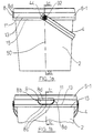
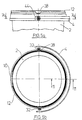
- the container (bucket or cup) 2 is, for example a mustard bucket with a handle 4 and a lid 6.
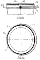
- the cover 6 can either be used as a sealing cover 6-1 (FIG. 1) or be designed as a slip lid 6-2 (Fig. 2).
- the container can have a tamper-evident protection 8 corresponding to the cover type a first embodiment shown in Fig. 1 or an exposed recessed grip 10 corresponding to one in Fig. 2 shown second embodiment.
- the tamper protection 8 ensures control of the integrity of an im Product 2 container. Protection of originality 8 is preferably a tamper-evident label that the end user must break open to engage in the recessed grip 10 and to open the lid 6-1.
- the tamper protection 8 shown in FIGS. 1a-1c can, for example, via a first predetermined breaking connection web 8a with the laterally adjoining edge of a peripheral wall of the Be connected to the container.
- a first predetermined breaking connection web 8a with the laterally adjoining edge of a peripheral wall of the Be connected to the container.
- the tamper-evident flap 8 On an opposite side the edge of the peripheral wall is the tamper-evident flap 8 with a flexible connecting band 8b on the container attached.
- the originality tab is in the area the lower edge over three further predetermined breaking links 8c connected to the peripheral wall. After leaving remains the tamper-evident tab 8 with the connecting tab 8b on one side on container 2 for better control and visibility hang.
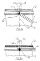
- the lid 6-1 sits on the container 2 so that an outer Circumferential section 11 with its lower edge region 13 or on a circumferential collar 15 formed on the container 2 sits so that the cover 6-1 is not without prior removal the tamper evident 8 can be removed because between Container 2 and lid 6-1 there is no possibility of intervention.
- the tamper-evident tab 8 has an offset to the outside and upward extension 8d. When put on This extension extends over the lower edge of the cover Cover.
- the lid 6-1 has a circumferential edge, which of a outer peripheral wall 11, an annular surface 17 (Fig. 1f) and Ring wall 19 (Fig. 2f) is formed.
- the annular wall 19 extends radially within the annular surface 17.
- the peripheral portion 11, the annular surface 17 and the annular wall 19 form one essentially U-shaped cross-sectional profile, which is about the Container circumference extends.
- the lid has one opposite Annular surface 17 offset central region 21.
- the individual sealing covers 6-1 are advantageously stacked one above the other.
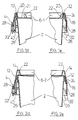
- the individual covers 6-1 on the inside of the outer peripheral wall 11 each preferably a circumferential Holding device 16 is provided, which is located on an upper outer edge 18 of the annular surface 17 of the respective underlying one Supported lid.
- the holding device 16 is for example a radially inward protruding tab or circumferential projection.
- the sealing cover 6-1 has on the underside of the ring surface 17 on a circumferential web, which together with a Part of the annular wall 19 has a preferably U-shaped sealing area 20 forms.
- the sealing area 20 is at the top Edge of the container 2 formed sealing edge 12 in engagement bringable that the container 2 with the lid 6-1 tight is lockable.
- the holding device 16 of the lid 6-1 is with an associated holding device 24 (Fig. 1e) on the edge of the container engaging. In this way, sealing and Holding area of the lid 6-1 on the container 2 spatial and functional separated from each other.
- 6-1 support elements on the lid 22 (Fig. 1e) to be provided, for example, from the edge portion extend the lid radially inwards.
- the support element 22 can run continuously along the circumference of the lid, provided in sections or only at individual points his.
- the shape or cross-sectional shape of the support elements 22 is for example parallelogram-like, as shown in Fig. 1f, can also have any other suitable support shape.
- the tamper evident 8 can be omitted so that an end user engage directly in the recessed grip 10 and the Can take off cover 6-2.
- a sealing film 14 is provided to ensure control the integrity of that in the bucket or cup 2 Product is at the top of the sealing edge 12 of the bucket / cup 2 .
- the slip lid 6-2 has like the one described above Sealing cover 6-1 a U-shaped ring profile 11, 17 and 19, wherein the sealing area 20 is omitted.
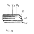
- the support wall 22 is advantageously, as in Fig. 2f shown in the U-shaped section of the edge region of the cover 6-2 trained. Support the support elements 22 on the cover 6-2 itself at the top of the sealing edge 12, so that the Middle region 21 of the lid no deeper than the sealing film 14 can be. Otherwise the holding area corresponds to Slip cover 6-2 essentially that of the sealing cover 6-1.
- the circumferential section 11 is advantageously of such a length that that the central region 21 of the lid 6-2 the sealing film 14 on Bucket or cup not damaged. Here is the bottom of the central region 21 is arranged approximately at the height of the container edge, when the lid is attached to the container.
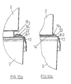
- FIGS. 10a and 10b show an alternative slip lid shape.
- the inner annular wall 19 is of stepped design with two wall sections 19 1 and 19 2 with different diameters.
- an annular plateau 19 3 is formed which supports stacking of the buckets or cups in a manner which prevents displacement (cf. FIGS. 10a and 10b).
- support elements 22 are formed in the U-shaped section of the edge region of the lid, which are supported on the upper ring edge / surface of the lid underneath.
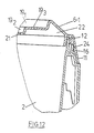
- 12 shows an enlarged partial view of a container closed with this cover (sealing cover 6-1).
- the container 2 can optionally be printed with an adhesive label or be provided with an inmold label.
- the head area of the Container 2 is universal for those described above Sealing and slip covers 6-1 and 6-2 are of the same design. It is it should be noted that the holding device 16 on the cover 6 in the holding device 24 provided on the container 2 engages, as can be seen in particular in FIGS. 1e and 2e.
- the Holding device 24 formed on container 2 is preferred a circumferential projection or a snap nose. When putting on and removing the lid 6 then becomes the one formed thereon Holding device 16 moves radially outward and holds the lid by engagement with the holding device 24 on the container fixes or releases it.
- the holding device 24 can run all round, be provided in sections or in places. As a result, the lid 6 is held securely on the container 2 guaranteed.
- the sealing area 20 is from the holding area 16/24 separated so that the same container with different Lids 6-1 or 6-2 can be used.
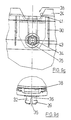
- hinge pins 32 are provided on both sides of the container 2, as shown in detail in Figures 9a to 9d.
- the hinge pins 32 are preferably made of two snap lugs 34, which yield resiliently when mounting the handle 4, educated. There is a free space 35 between the snap noses 34 provided, in which the snap lugs 34 when pressed together dodge.
- a support element 36 is provided in the free space, which forms a continuation of the hinge pin 32.
- This Support element 36 transmits essentially vertically acting Forces from the handle 4 to the container 2 and prevents possible unintentional squeezing of the snap noses 34 inside.
- the snap lugs 34 each have a spring section 37 and a hook section provided radially outside thereon 39 on. To assemble the handle 4, this is via the preferably beveled hook section 39 pushed and then rotatable about the hinge pin 32 held by the inside of the hook portion 39 the handle 4 holds in the radial direction of the container 2.
- This arrangement also has the advantage that the individual lots are thin-walled be formed. This allows good manufacturability under Compliance with required dimensional tolerances.
- hinge pin 32 is in the figures 9c and 9d. There is no separate space 35 here Support element 36 is provided. At the end of the container Hinge pin, the two snap lugs 34 with each other connected so that the free space 35 does not extend all the way to the container wall extends. The free space preferably extends over at least 50% of the area of the pin 32 in which the Handle 4 supports.
- the snap lugs 34 have a hook section 39, which is preferably bevelled on the outside.
- the Snap noses are roughly crescent-shaped, interrupted from the groove-shaped free space 35 (see FIG. 9c).
- hinge pin 32 on the container 2 enables in particular that in the space between the edge region 28th and the outer wall 26 of the container 2 an additional space for an anti-rotation device is created. This is usually not the case the case because the hinge pins are provided on the handle and protrude through openings in the container into this space. Nevertheless, it is also with the container according to the invention 2 possible to reverse the hinge assembly, then the Protection against rotation can also be provided outside the hinge area is.
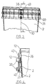
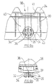
- Figures 3 and 4 show the stackability of the invention Container 2. Sit as described above, the ribs 30 on the container rim of an underlying container. The containers 2 are secured against rotation in the stack. For this purpose, in the upper edge area of the container, i.e. in the holding device 24 but not a recess in the sealing edge 12 38 is provided, into which a between the outer wall 26 and the securing element 40 located in the turned-over region 28 intervenes.
- the recess 38 and / or the securing element 40 point / point at least partially beveled or rounded Sections 41 and 43 so that even if the container 2 the elements of the Anti-rotation lock 38 and 40 engage in one another by the inclined or rounded edges 43 of the securing element 40 slide along portions 41 of recess 38.
- the recess 38 and / or the securing element 40 preferably run symmetrical between preferably 30 ° and 60 ° conical downward.
- the securing element 40 can, for example, similar to that shown in Figs. 7a and 7b, by at least a connecting web 42 may be attached to the container 2.
- the Securing element 40 can preferably also by at least one of the stiffening ribs 30 on one of the web 42 opposite side thereof are supported, whereby a stabilization of the arrangement when mounting the handle 4 is achievable.
- the bevel preferably extends or rounding 41 at the recess 38 over its entire depth, while on the securing element 40 only the corners are generous beveled or rounded.
- the anti-rotation lock has the Advantage that the containers are in a certain position to each other are stackable, the assembled handle 4, which from Not shown in these figures for reasons of clarity are arranged one above the other in the specified position are. As will be explained in more detail below, thereby exact handling for the further work steps ensured.
- Figures 13-15 show an anti-rotation device according to an alternative Embodiment.
- the sword shown in Figs. 3 and 4 40 is replaced here by two walls 40. These walls or Crosspieces extend essentially perpendicular to the container wall 26 between the container wall and the inverted area 28.
- the webs 40 are thus similar to the ribs 30, however, extend further down (see FIG. 13), so that they are in the recess 38 of an underlying one Intervene in the container to prevent rotation.
- the container handles on the market each have one semicircular end that is centered around the hinge pin is.
- a driver 44 is provided through which the handle 4 in cooperation with a handling system in a Longitudinal axis 50 of the container vertical position can be brought.
- the driver 44 is, for example, about the pivot point of the Henkels 4 protruding section on which the handling system can attack.
- the driver 44 can, for example, as Lever, recess, projection or the like can be formed.
- the container 2 according to the invention preferably has a handle 4 on the beyond the hinge pin 32 in its Longitudinal direction around an extension portion 44 is preferred is extended in parallel.
- an alignment element 46 acts on the extension section 44.
- Such one Alignment element 46 is, for example, in FIGS. 8a and 8b with a dash-dotted line.
- the alignment element 46 is, for example, a spring-loaded alignment part, that is integrated in the handling system.
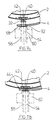
- To handle of a stacked container 2 according to the invention meets this Alignment element 46, as shown in Fig. 8a, in a vertical Movement along arrow 48 to the first obliquely upward extending portion 44 of the handle 4.
- the handle 4 is forced into one position perpendicular to the longitudinal axis 50 of the container 2. In order to is the danger that the handle 4 of the top container hooked with a container underneath, excluded, and easy handling of the container according to the invention 2 is guaranteed.
- the handle 4 of the invention Container 2 preferably a diamond or dragon shape on. This facilitates the manufacture of the injection mold as well as demolding. Furthermore, the handle 4 in the area of Openings 52 preferably one on both sides annular projection on (see. Fig. 5b). Inside serves the Projection as a spacer to the container and covers the outside Projection from the free space 35 of the hinge pin 32.
- the container 2 of the present invention is preferably a injection molded plastic bucket or cup that comes in one Injection molding machine is manufactured with an injection mold, the handle 4 provided on the container 2 in one operation is injected and assembled together with the container 2.
- the device for manufacturing or the injection mold as can be seen in particular from FIG. that the container 2 and the handle 4 so in the injection mold lie that automatically remove the handle 4 can be mounted on container 2.
- the handle 4 is substantially half the circumference of the container 2 extends, the handle substantially provided perpendicular to the longitudinal axis 50 of the container 2 in the form and the openings 52 at the end portions of the handle 4 align with the hinge pin 32. Because it is then according to FIGS.
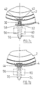
- the handle 4 on the container 2 during the demolding to assemble is preferably in the injection mold a mandrel 54 is provided, which the openings 52 on the handle 4th formed.
- the mandrel 54 is used during assembly Demoulding as a guide for the handle 4 itself, so that this exactly to and over the snap lugs 34 on the hinge pin 32 can be performed.
- the injection mold a shaped sleeve 56 on the one hand, a stepped recess 58 trained in the handle hub and on the other hand as a guide a mounting sleeve 60 is used.
- the mounting sleeve 60 presses when opening the mold the handle 4 on the hinge pin 32, as shown in Fig. 7b.
- Assembly during demolding can take place, for example, that after spraying, the outer shape is removed first is so that the exterior of the container 2 and part of the Handle 4 are exposed. In a next step or simultaneously the container 2 and the handle 4 are removed from the mold so far, that the inner mandrel essentially inside the container remains, but the hinge pins 32 are exposed on the container. The handle 4 is then by means of the mandrel 54, the mold sleeve 56 and the mounting sleeve 60 mounted. Finally the inner mold core, which is used to stabilize the container 2 during serves for assembly, removed.
- the mandrel 54 has another for the handle openings -
- the core 55 is arranged concentrically on the inside. This protrudes into the hinge pin 32 during injection molding, so the inner surface of the crescent-shaped snap noses 34, i.e. to form the frustoconical free space 35 (see FIG. 7c and 7d).
- the container 2 itself is through an exchange insert in the Injection mold optionally as a tamper-evident container 8 or with an open recessed grip 10. So leave with the injection mold according to the invention both above Spray the described container types according to Figures 1 and 2.
- FIG. 10a shows a cutout of two stacked one on top of the other Cup with sealing lid 6-1.
- a first floor design preferably with one foot on the stepped middle area 21 stands.
- the stepped wall section 19 represents a stepped Stack lock ready, which is a move of the top Mug relative to the cup underneath prevented or at least limited.
- a cup or bucket with one second floor design stacked without a corresponding foot (see Fig. 10b)
- the underside of the cup / bucket rests the ring-shaped plateau and is also there against slipping secured.
- a single lid shape for cups / buckets can be used with or without a foot.
- Figure 15 shows a further alternative floor design.
- the bottom of the container initially runs in one Plane perpendicular to the container axis, but then forms one foot protruding beyond the lower edge of the outer wall of the container out. This creates a concentric between the foot and the overhang Groove 71.
- the cups can be provided with or without a handle and in different sizes, for example according to the following table: Top diameter (mm) Cup content (ml) 77 125 ⁇ 200 200 250 96 250 400 500 109 250 400 500 750 120 500 750 1000
- the same lid size can be used for all cups in a row in Table 1 can be used as foot and top diameter for all cup sizes is the same.
Landscapes
- Engineering & Computer Science (AREA)
- Mechanical Engineering (AREA)
- Manufacturing & Machinery (AREA)
- Stackable Containers (AREA)
- Processing And Handling Of Plastics And Other Materials For Molding In General (AREA)
Applications Claiming Priority (4)
| Application Number | Priority Date | Filing Date | Title |
|---|---|---|---|
| DE19906441 | 1999-02-16 | ||
| DE19906441A DE19906441A1 (de) | 1999-02-16 | 1999-02-16 | Kunststoffeimer und Verfahren sowie Vorrichtung zu dessen Herstellung und Handhabung |
| DE19960270 | 1999-12-14 | ||
| DE19960270 | 1999-12-14 |
Publications (2)
| Publication Number | Publication Date |
|---|---|
| EP1029796A1 EP1029796A1 (de) | 2000-08-23 |
| EP1029796B1 true EP1029796B1 (de) | 2002-06-05 |
Family
ID=26051887
Family Applications (1)
| Application Number | Title | Priority Date | Filing Date |
|---|---|---|---|
| EP00102253A Expired - Lifetime EP1029796B1 (de) | 1999-02-16 | 2000-02-15 | Kunststoffbehälter und Verfahren sowie Vorrichtung zu dessen Herstellung und Handhabung |
Country Status (5)
| Country | Link |
|---|---|
| EP (1) | EP1029796B1 (cs) |
| AT (1) | ATE218468T1 (cs) |
| CZ (1) | CZ2000555A3 (cs) |
| DE (1) | DE50000187D1 (cs) |
| PL (1) | PL338468A1 (cs) |
Families Citing this family (7)
| Publication number | Priority date | Publication date | Assignee | Title |
|---|---|---|---|---|
| DE10038386C2 (de) * | 2000-08-07 | 2002-11-07 | Grt Verpackungen Aus Kunststof | Kunststoffbehälter sowie Verfahren und Vorrichtung zu seiner Herstellung |
| DK200100515A (da) * | 2001-03-28 | 2002-09-29 | Superfos As | Sprøjtestøbeværktøj |
| DE202005012314U1 (de) * | 2005-08-05 | 2006-03-02 | Pöppelmann Holding GmbH & Co. KG | Kunststoffbehälter |
| IT1395152B1 (it) * | 2009-08-07 | 2012-09-05 | Casone Spa | Stampo a iniezione per contenitori in materiale plastico con manico imperniato |
| ITPR20120061A1 (it) * | 2012-10-05 | 2014-04-06 | Casone Spa | Metodo per formare un contenitore in plastica provvisto di manico con unica fase di stampaggio; stampo atto a realizzare detto metodo. |
| CN105618948B (zh) * | 2016-03-17 | 2017-09-22 | 广东顺德凯南德机械有限公司 | 一种用于提梁和耳壳的组合装置 |
| SG11202006776XA (en) * | 2018-02-05 | 2020-08-28 | Crown Packaging Technology Inc | Handle for a nestable container |
Family Cites Families (5)
| Publication number | Priority date | Publication date | Assignee | Title |
|---|---|---|---|---|
| DE2328214A1 (de) * | 1973-06-02 | 1974-12-19 | Raymond August Heisler | Behaelter mit einem auf seinen oeffnungswulst aufsetzbaren deckel |
| US3967731A (en) * | 1975-02-03 | 1976-07-06 | Dart Industries Inc. | Stackable lid and container |
| US5111954A (en) * | 1990-10-02 | 1992-05-12 | Ipl Inc. | Tamper evident container |
| DE4444573A1 (de) * | 1994-12-14 | 1996-06-20 | Grt Verpackung Aus Kunststoff | Originalitätsgesicherter Behälter |
| DE29802048U1 (de) * | 1998-02-09 | 1998-04-02 | Jokey Plastik Wipperfürth GmbH, 51688 Wipperfürth | Farbdose |
-
2000
- 2000-02-15 EP EP00102253A patent/EP1029796B1/de not_active Expired - Lifetime
- 2000-02-15 DE DE50000187T patent/DE50000187D1/de not_active Expired - Fee Related
- 2000-02-15 AT AT00102253T patent/ATE218468T1/de not_active IP Right Cessation
- 2000-02-16 CZ CZ2000555A patent/CZ2000555A3/cs unknown
- 2000-02-16 PL PL00338468A patent/PL338468A1/xx unknown
Also Published As
| Publication number | Publication date |
|---|---|
| EP1029796A1 (de) | 2000-08-23 |
| DE50000187D1 (de) | 2002-07-11 |
| PL338468A1 (en) | 2000-08-28 |
| CZ2000555A3 (cs) | 2001-12-12 |
| ATE218468T1 (de) | 2002-06-15 |
Similar Documents
| Publication | Publication Date | Title |
|---|---|---|
| DE69605534T2 (de) | Anordnung mit spülkopf und abdeckkappe | |
| DE69808491T2 (de) | Ventil für verpackungsbehälter | |
| DE69227371T2 (de) | Sanitärer dosenträger | |
| DE202009016507U1 (de) | Behälter umfassend einen wiederverschließbaren Deckel mit einem elastischen Ring | |
| EP1254842A1 (de) | Kunststoffbehälter | |
| EP1194342B1 (de) | Zweiteiliger schnappscharnierverschluss aus kunststoff | |
| WO1999039982A2 (de) | Farbdose | |
| DE1536105B1 (de) | Verschluss fuer Behaelter | |
| DE69906565T2 (de) | Handmühle für körnige nahrungsmittel | |
| DE2549400C3 (de) | Kunststoffbehälter | |
| DE1942312C3 (de) | Durch axiales Aufpressen auf den Hals einer Flasche aufbringbare Verschlußkappe | |
| EP1029796A1 (de) | Kunststoffbeh-lter und Verfahren sowie Vorrichtung zu dessen Herstellung und Handhabung | |
| DE10038386C2 (de) | Kunststoffbehälter sowie Verfahren und Vorrichtung zu seiner Herstellung | |
| EP1670692A1 (de) | Behälter | |
| DE2825837C3 (de) | Aus Kunststoff-Folie geformter Behälter | |
| DE1196119B (de) | Topffoermige Abdeckkappe aus Kunststoffmaterial fuer Dosen, insbesondere Aerosoldosen | |
| DE10230695B4 (de) | Behälterdeckel aus Kunststoff | |
| EP3344559B1 (de) | Getraenkedosenverschluss sowie doseneinheit aus getraenkedose und verschluss | |
| EP0882649B1 (de) | Verfahren zum Verbinden eines Unterteils eines Verpackungsbehälters mit einem Verschlusselement | |
| DE19906441A1 (de) | Kunststoffeimer und Verfahren sowie Vorrichtung zu dessen Herstellung und Handhabung | |
| CH607701A5 (en) | Container with lid | |
| EP0536613B1 (de) | Kunststoffeimer und Deckel mit kragenförmigem Abstandhalter und verdecktem Klemmverschluss | |
| DE8715009U1 (de) | Behälter mit Deckel | |
| DE102010034856B4 (de) | Arretierbare Betätigungsvorrichtung für ein Dosiersystem eines Behältnisses | |
| EP3730418B1 (de) | Behälter |
Legal Events
| Date | Code | Title | Description |
|---|---|---|---|
| PUAI | Public reference made under article 153(3) epc to a published international application that has entered the european phase |
Free format text: ORIGINAL CODE: 0009012 |
|
| AK | Designated contracting states |
Kind code of ref document: A1 Designated state(s): AT BE CH CY DE DK ES FI FR GB GR IE IT LI LU MC NL PT SE |
|
| AX | Request for extension of the european patent |
Free format text: AL;LT;LV;MK;RO;SI |
|
| 17P | Request for examination filed |
Effective date: 20000804 |
|
| 17Q | First examination report despatched |
Effective date: 20001012 |
|
| AKX | Designation fees paid |
Free format text: AT BE CH CY DE DK ES FI FR GB GR IE IT LI LU MC NL PT SE |
|
| AXX | Extension fees paid |
Free format text: LT PAYMENT 20000915;LV PAYMENT 20000915 |
|
| GRAG | Despatch of communication of intention to grant |
Free format text: ORIGINAL CODE: EPIDOS AGRA |
|
| GRAG | Despatch of communication of intention to grant |
Free format text: ORIGINAL CODE: EPIDOS AGRA |
|
| GRAH | Despatch of communication of intention to grant a patent |
Free format text: ORIGINAL CODE: EPIDOS IGRA |
|
| RIN1 | Information on inventor provided before grant (corrected) |
Inventor name: HEYN, KLAUS |
|
| GRAH | Despatch of communication of intention to grant a patent |
Free format text: ORIGINAL CODE: EPIDOS IGRA |
|
| GRAA | (expected) grant |
Free format text: ORIGINAL CODE: 0009210 |
|
| AK | Designated contracting states |
Kind code of ref document: B1 Designated state(s): AT BE CH CY DE DK ES FI FR GB GR IE IT LI LU MC NL PT SE |
|
| AX | Request for extension of the european patent |
Free format text: LT PAYMENT 20000915;LV PAYMENT 20000915 |
|
| PG25 | Lapsed in a contracting state [announced via postgrant information from national office to epo] |
Ref country code: IT Free format text: LAPSE BECAUSE OF FAILURE TO SUBMIT A TRANSLATION OF THE DESCRIPTION OR TO PAY THE FEE WITHIN THE PRESCRIBED TIME-LIMIT;WARNING: LAPSES OF ITALIAN PATENTS WITH EFFECTIVE DATE BEFORE 2007 MAY HAVE OCCURRED AT ANY TIME BEFORE 2007. THE CORRECT EFFECTIVE DATE MAY BE DIFFERENT FROM THE ONE RECORDED. Effective date: 20020605 Ref country code: IE Free format text: LAPSE BECAUSE OF FAILURE TO SUBMIT A TRANSLATION OF THE DESCRIPTION OR TO PAY THE FEE WITHIN THE PRESCRIBED TIME-LIMIT Effective date: 20020605 Ref country code: GR Free format text: LAPSE BECAUSE OF FAILURE TO SUBMIT A TRANSLATION OF THE DESCRIPTION OR TO PAY THE FEE WITHIN THE PRESCRIBED TIME-LIMIT Effective date: 20020605 Ref country code: GB Free format text: LAPSE BECAUSE OF FAILURE TO SUBMIT A TRANSLATION OF THE DESCRIPTION OR TO PAY THE FEE WITHIN THE PRESCRIBED TIME-LIMIT Effective date: 20020605 Ref country code: FI Free format text: LAPSE BECAUSE OF FAILURE TO SUBMIT A TRANSLATION OF THE DESCRIPTION OR TO PAY THE FEE WITHIN THE PRESCRIBED TIME-LIMIT Effective date: 20020605 |
|
| REF | Corresponds to: |
Ref document number: 218468 Country of ref document: AT Date of ref document: 20020615 Kind code of ref document: T |
|
| REG | Reference to a national code |
Ref country code: GB Ref legal event code: FG4D Free format text: NOT ENGLISH |
|
| REG | Reference to a national code |
Ref country code: CH Ref legal event code: NV Representative=s name: E. BLUM & CO. PATENTANWAELTE Ref country code: CH Ref legal event code: EP |
|
| REG | Reference to a national code |
Ref country code: IE Ref legal event code: FG4D Free format text: GERMAN |
|
| REF | Corresponds to: |
Ref document number: 50000187 Country of ref document: DE Date of ref document: 20020711 |
|
| PG25 | Lapsed in a contracting state [announced via postgrant information from national office to epo] |
Ref country code: SE Free format text: LAPSE BECAUSE OF FAILURE TO SUBMIT A TRANSLATION OF THE DESCRIPTION OR TO PAY THE FEE WITHIN THE PRESCRIBED TIME-LIMIT Effective date: 20020905 Ref country code: PT Free format text: LAPSE BECAUSE OF FAILURE TO SUBMIT A TRANSLATION OF THE DESCRIPTION OR TO PAY THE FEE WITHIN THE PRESCRIBED TIME-LIMIT Effective date: 20020905 Ref country code: DK Free format text: LAPSE BECAUSE OF FAILURE TO SUBMIT A TRANSLATION OF THE DESCRIPTION OR TO PAY THE FEE WITHIN THE PRESCRIBED TIME-LIMIT Effective date: 20020905 |
|
| ET | Fr: translation filed | ||
| GBV | Gb: ep patent (uk) treated as always having been void in accordance with gb section 77(7)/1977 [no translation filed] |
Effective date: 20020605 |
|
| PG25 | Lapsed in a contracting state [announced via postgrant information from national office to epo] |
Ref country code: ES Free format text: LAPSE BECAUSE OF FAILURE TO SUBMIT A TRANSLATION OF THE DESCRIPTION OR TO PAY THE FEE WITHIN THE PRESCRIBED TIME-LIMIT Effective date: 20021220 |
|
| LTIE | Lt: invalidation of european patent or patent extension |
Effective date: 20020605 |
|
| PG25 | Lapsed in a contracting state [announced via postgrant information from national office to epo] |
Ref country code: LU Free format text: LAPSE BECAUSE OF NON-PAYMENT OF DUE FEES Effective date: 20030215 Ref country code: CY Free format text: LAPSE BECAUSE OF FAILURE TO SUBMIT A TRANSLATION OF THE DESCRIPTION OR TO PAY THE FEE WITHIN THE PRESCRIBED TIME-LIMIT Effective date: 20030215 |
|
| REG | Reference to a national code |
Ref country code: IE Ref legal event code: FD4D Ref document number: 1029796E Country of ref document: IE |
|
| PG25 | Lapsed in a contracting state [announced via postgrant information from national office to epo] |
Ref country code: MC Free format text: LAPSE BECAUSE OF NON-PAYMENT OF DUE FEES Effective date: 20030228 |
|
| PLBE | No opposition filed within time limit |
Free format text: ORIGINAL CODE: 0009261 |
|
| STAA | Information on the status of an ep patent application or granted ep patent |
Free format text: STATUS: NO OPPOSITION FILED WITHIN TIME LIMIT |
|
| 26N | No opposition filed |
Effective date: 20030306 |
|
| REG | Reference to a national code |
Ref country code: CH Ref legal event code: PUE Owner name: ABRO WEIDENHAMMER GMBH Free format text: GRT VERPACKUNGEN AUS KUNSTSTOFF GMBH#BROESENER STRASSE 10#04539 GROITZSCH (DE) -TRANSFER TO- ABRO WEIDENHAMMER GMBH#1. INDUSTRIESTRASSE 26#68766 HOCKENHEIM (DE) |
|
| PGFP | Annual fee paid to national office [announced via postgrant information from national office to epo] |
Ref country code: FR Payment date: 20060217 Year of fee payment: 7 |
|
| PGFP | Annual fee paid to national office [announced via postgrant information from national office to epo] |
Ref country code: CH Payment date: 20060220 Year of fee payment: 7 Ref country code: BE Payment date: 20060220 Year of fee payment: 7 |
|
| PGFP | Annual fee paid to national office [announced via postgrant information from national office to epo] |
Ref country code: AT Payment date: 20060221 Year of fee payment: 7 |
|
| PGFP | Annual fee paid to national office [announced via postgrant information from national office to epo] |
Ref country code: NL Payment date: 20060223 Year of fee payment: 7 |
|
| NLS | Nl: assignments of ep-patents |
Owner name: ABRO WEIDENHAMMER GMBH Effective date: 20060206 |
|
| REG | Reference to a national code |
Ref country code: FR Ref legal event code: TP |
|
| PG25 | Lapsed in a contracting state [announced via postgrant information from national office to epo] |
Ref country code: LI Free format text: LAPSE BECAUSE OF NON-PAYMENT OF DUE FEES Effective date: 20070228 Ref country code: CH Free format text: LAPSE BECAUSE OF NON-PAYMENT OF DUE FEES Effective date: 20070228 |
|
| PGFP | Annual fee paid to national office [announced via postgrant information from national office to epo] |
Ref country code: DE Payment date: 20070329 Year of fee payment: 8 |
|
| REG | Reference to a national code |
Ref country code: CH Ref legal event code: PL |
|
| NLV4 | Nl: lapsed or anulled due to non-payment of the annual fee |
Effective date: 20070901 |
|
| PG25 | Lapsed in a contracting state [announced via postgrant information from national office to epo] |
Ref country code: AT Free format text: LAPSE BECAUSE OF NON-PAYMENT OF DUE FEES Effective date: 20070215 |
|
| REG | Reference to a national code |
Ref country code: FR Ref legal event code: ST Effective date: 20071030 |
|
| BERE | Be: lapsed |
Owner name: *ABRO WEIDENHAMMER G.M.B.H. Effective date: 20070228 |
|
| PG25 | Lapsed in a contracting state [announced via postgrant information from national office to epo] |
Ref country code: BE Free format text: LAPSE BECAUSE OF NON-PAYMENT OF DUE FEES Effective date: 20070228 |
|
| PG25 | Lapsed in a contracting state [announced via postgrant information from national office to epo] |
Ref country code: NL Free format text: LAPSE BECAUSE OF NON-PAYMENT OF DUE FEES Effective date: 20070901 |
|
| PG25 | Lapsed in a contracting state [announced via postgrant information from national office to epo] |
Ref country code: FR Free format text: LAPSE BECAUSE OF NON-PAYMENT OF DUE FEES Effective date: 20070228 |
|
| PG25 | Lapsed in a contracting state [announced via postgrant information from national office to epo] |
Ref country code: DE Free format text: LAPSE BECAUSE OF NON-PAYMENT OF DUE FEES Effective date: 20080902 |