EP1029259B1 - Umdruckstation für ein elektrografisches gerät mit einem andruckelement im umdruckbereich - Google Patents
Umdruckstation für ein elektrografisches gerät mit einem andruckelement im umdruckbereich Download PDFInfo
- Publication number
- EP1029259B1 EP1029259B1 EP98959849A EP98959849A EP1029259B1 EP 1029259 B1 EP1029259 B1 EP 1029259B1 EP 98959849 A EP98959849 A EP 98959849A EP 98959849 A EP98959849 A EP 98959849A EP 1029259 B1 EP1029259 B1 EP 1029259B1
- Authority
- EP
- European Patent Office
- Prior art keywords
- transfer printing
- contact pressure
- intermediate carrier
- pressure element
- recording medium
- Prior art date
- Legal status (The legal status is an assumption and is not a legal conclusion. Google has not performed a legal analysis and makes no representation as to the accuracy of the status listed.)
- Expired - Lifetime
Links
Images



Classifications
-
- G—PHYSICS
- G03—PHOTOGRAPHY; CINEMATOGRAPHY; ANALOGOUS TECHNIQUES USING WAVES OTHER THAN OPTICAL WAVES; ELECTROGRAPHY; HOLOGRAPHY
- G03G—ELECTROGRAPHY; ELECTROPHOTOGRAPHY; MAGNETOGRAPHY
- G03G15/00—Apparatus for electrographic processes using a charge pattern
- G03G15/14—Apparatus for electrographic processes using a charge pattern for transferring a pattern to a second base
- G03G15/16—Apparatus for electrographic processes using a charge pattern for transferring a pattern to a second base of a toner pattern, e.g. a powder pattern, e.g. magnetic transfer
- G03G15/163—Apparatus for electrographic processes using a charge pattern for transferring a pattern to a second base of a toner pattern, e.g. a powder pattern, e.g. magnetic transfer using the force produced by an electrostatic transfer field formed between the second base and the electrographic recording member, e.g. transfer through an air gap
- G03G15/1635—Apparatus for electrographic processes using a charge pattern for transferring a pattern to a second base of a toner pattern, e.g. a powder pattern, e.g. magnetic transfer using the force produced by an electrostatic transfer field formed between the second base and the electrographic recording member, e.g. transfer through an air gap the field being produced by laying down an electrostatic charge behind the base or the recording member, e.g. by a corona device
- G03G15/164—Apparatus for electrographic processes using a charge pattern for transferring a pattern to a second base of a toner pattern, e.g. a powder pattern, e.g. magnetic transfer using the force produced by an electrostatic transfer field formed between the second base and the electrographic recording member, e.g. transfer through an air gap the field being produced by laying down an electrostatic charge behind the base or the recording member, e.g. by a corona device the second base being a continuous paper band, e.g. a CFF
-
- G—PHYSICS
- G03—PHOTOGRAPHY; CINEMATOGRAPHY; ANALOGOUS TECHNIQUES USING WAVES OTHER THAN OPTICAL WAVES; ELECTROGRAPHY; HOLOGRAPHY
- G03G—ELECTROGRAPHY; ELECTROPHOTOGRAPHY; MAGNETOGRAPHY
- G03G2215/00—Apparatus for electrophotographic processes
- G03G2215/00362—Apparatus for electrophotographic processes relating to the copy medium handling
- G03G2215/00443—Copy medium
- G03G2215/00451—Paper
- G03G2215/00455—Continuous web, i.e. roll
-
- G—PHYSICS
- G03—PHOTOGRAPHY; CINEMATOGRAPHY; ANALOGOUS TECHNIQUES USING WAVES OTHER THAN OPTICAL WAVES; ELECTROGRAPHY; HOLOGRAPHY
- G03G—ELECTROGRAPHY; ELECTROPHOTOGRAPHY; MAGNETOGRAPHY
- G03G2215/00—Apparatus for electrophotographic processes
- G03G2215/00362—Apparatus for electrophotographic processes relating to the copy medium handling
- G03G2215/00919—Special copy medium handling apparatus
- G03G2215/00924—Special copy medium handling apparatus two or more parallel feed paths
Definitions
- the invention relates to a transfer printing station with a electrostatic transfer printing device for transferring a an electrographic intermediate carrier generated toner image on at least one record carrier in one Transfer area of the transfer station, in the transfer area arranged guide elements for guiding the Record carrier near the intermediate carrier during the transfer printing process, and with one between the guide elements arranged pressure element, which the record carrier presses against the intermediate carrier during the transfer printing process.
- Such a transfer printing station is known from US 5,400,125. It uses a leaf-shaped as a pressure element Blade with the edge of the tape-shaped record carrier against the electrographic intermediate carrier, a photoconductor drum, suppressed. Although relatively good with this solution practical results could be obtained nevertheless some disadvantages. So is the blade-shaped pressure element a wearing part, the service life of which is relatively short and requires frequent replacement. Because the edge of the blade the pressure element rubs on the recording medium, results in the transfer printing area from toner abrasion and paper abrasion significant pollution. If different Web widths of the record carrier are used, so must a pressure element matched to this web width be used. In addition, the blade-shaped Pressure element irregularities in the electrostatic Field in transfer area; these irregularities can Create stripes in the printed image.
- JP-A-7-84468 is a transfer printing station with one Pressure element known in the transfer printing area.
- the pressure element is formed on a guide element, the Transfer station only a single guide element contains.
- the pressure element is designed as a pressure roller and has side support wheels, which are located on the edge of a Support intermediate support that has no imaging function to have.
- the record carrier becomes close with an edge fed a jockey wheel.
- the other jockey wheel has one larger diameter than the first mentioned support wheel, whereby there is a wedge-shaped gap between the surface of the Pinch roller and the surface of the intermediate carrier formed. This ensures that the pressure roller in Area of the enlarged gap not with toner material is applied.
- DE-A-195 41 061 is an electrographic printer known, in which two adjacent tracks one Record carrier can be printed simultaneously. One of the Sheets may have already gone through a fusing process.
- a transfer printing station Type mentioned so that on the one hand to Generation of a print image with high quality Pressure element also deformed unevenly Record carriers of different thicknesses or readings evenly applied to the intermediate carrier during transfer printing and that on the other hand in all operating conditions it is ensured that the pressure element is not in contact reached with the intermediate carrier.
- This task is carried out according to the characteristics of the 1st Claim resolved.
- the pressure element which as a pressure roller or as Pressure rail is formed and essentially over the entire width of the electrographic intermediate carrier, e.g. a photoconductor drum, is rigid trained and instructed to maintain a defined Minimum distance between pressure element and intermediate carrier, a spacer element supported on the intermediate carrier preferably in the form of a support roller.
- the pressure element is designed as a pressure roller, it rolls on the record carrier and it just arises Rolling friction between the record carrier and the Pinch roller. Accordingly, the abrasion on the record carrier reduced and the risk of pollution is small.
- the surface is of the pressure element is electrically conductive and has a predetermined electrical potential, preferably Ground potential.
- a predetermined electrical potential preferably Ground potential.
- a preferred embodiment of the invention is thereby characterized in that the pressure element has two support rollers, whose diameters are such that a minimum distance not between the pressure element and the intermediate carrier is undercut.
- a Transfer printing process i.e. with a Provide toner image and over a longer transport route promoted and possibly subjected to heat setting has been.
- these waves and grooves smoothed in the transfer printing area so that the recording medium full surface on the intermediate carrier for the transfer of toner is applied.
- FIG. 1 shows part of an electrophotographic printing device, which is shown schematically in the figure Transfer station contains.
- This transfer station serves a toner image generated on a photoconductor drum 10 on a tape-shaped recording medium, in the present Case of a smooth or pre-folded continuous paper 12, too transfer.
- This process is known as transfer printing.
- the Transfer printing takes place as part of an electrophotographic process, in which the photoconductor drum 10 is first used a charging device (not shown) to about 500 V. evenly charged and then using a character dependent controlled exposure device in the range of about 70 V is discharged in places. A latent created in this way Character image is then in the usual way in a developer station (not shown) using a two-component mixture from toner particles and ferromagnetic carrier particles inked.
- the toner particles are positively charged triboelectrically. Between a developer roller of the developer station that a basic potential of about 220 V, and about 70 V discharged areas of the latent character image a field that causes the toner particles on the discharged Areas. From the unexposed area with a The toner particles become a charging voltage of about 500 V. repelled.
- the toner image thus formed from loose toner particles is then using a strong generated by a corotron wire 14 negative electrostatic field on the tape-shaped recording medium 12 transferred.
- the corotron wire 14 is on one side shielded by a corrotron screen 16; its electric field acts through the opening gap between two transfer printing jaws 18, 20 through the recording medium 12 through, thereby removing the toner particles from the photoconductor drum 10 detached and on the in touch contact with the Transferred photoconductor 10 located recording medium 12, where they stick electrostatically.
- the toner images thus transferred in a thermal printing fixing station (not shown) between a heated fuser roller and a pressure roller in the surface of the recording medium 12 melted down.
- the end plays a critical role in the state of the art 22 of the transfer printing jaw feeding the recording medium 12 18.
- the feed direction for the recording medium 12 results itself from the movement of the photoconductor drum 10 as it goes through an arrow P1 is indicated.
- This end 22 cannot be in intimate contact with the photoconductor drum 10, since the risk of injury to the sensitive surface of the Photoconductor drum 10 is too large.
- the record carrier 12 this contact with the surface of the Have photoconductor drum 10 to transfer the toner particles. If the carrier material has minor defects or unevenness , they have a special effect at the end of 22 critically, so that the transfer of toner particles is not done evenly.
- FIG. 2 shows a solution from the prior art as it in U.S. Patent No. 5,400,125 by the same applicant.
- This document which provides further details of the relevant here Transfer station shows hereby in this patent application included as a source of disclosure.
- the well-known solution uses a blade-like pressure element 24, which is arranged at the end 22 of the transfer printing jaw 18 and with it Blade edge a defined contact between record carriers 12 and surface of the photoconductor drum 10.
- This solution has proven itself in practice however, the disadvantages are that the pressure element 24 wears out over time and must be replaced, whereby the printing process is disrupted. With a high degree of wear of the pressure element 24 arise print image errors. Farther abrasion occurs on the pressure element 24 and on the recording medium 12, causing pollution and another Source of interference.
- FIG. 3 shows an embodiment of the invention in a perspective view, the same parts denoted the same are.
- the transfer printing jaw is on the 18th a pressure roller 26 stored, which extends over the entire length the photoconductor drum 10 extends.
- support rollers 28 are attached, which together with the Turn transfer roller 26.
- the transfer printing jaw 18 can be one
- the axis of rotation 19 is pivoted away from the surface of the photoconductor drum 10 and swung back towards them, whereby the pinch roller 26 movements according to arrows P2 and P3 performs.
- the support rollers 28 have a diameter that so is dimensioned so that it is on the Surface of the photoconductor drum 10 on its outermost portions roll.
- the radius of the Support rollers 28 may be slightly larger than the sum of the Radius of the pressure roller 26 and the thickness of the recording medium.
- 70 to 160 g should be the difference between the radii of support roller 28 and pressure roller 26 approximately 15/100 mm ⁇ 10%.
- the support rollers 28 ensure that on the one hand the Record carrier 12 in a defined vicinity of the photoconductor drum 10 is brought, the rolling friction between Record carrier 12 and pressure roller 26 is minimal. on the other hand cause the support rollers 28 that even with a record carrier 12, the width of which is less than the length the photoconductor drum 10 seen in the longitudinal axis, which is an injury the photosensitive surface does not appear. It So any web widths can be reprinted, which in particular with a long length of the photoconductor drum 10 is advantageous.
- the recording medium has two tracks 12A and 12B, which are side by side are arranged.
- the transfer station shown is thus suitable for use in a so-called duplex operation, in which a path of the record carrier on the one Side is printed, then the web after heat setting around Turned 180 ° and the same transfer station with the other Page fed and then reprinted. With one So the transfer station will still be a first operating mode unprinted web 12A and an already printed web 12B fed. The already printed web 12B has due to the Heat setting often waves and a different surface texture.
- the pressure roller 26 now achieves that even with two adjacent lanes with different Surfaces and different properties nevertheless both tracks are even and smooth on the surface the photoconductor drum 10 rest, so that a perfect Transfer printing can take place. Because the support rollers 28 on the surface roll the photoconductor drum 10, shape deviations affect not from the ideal cylindrical shape, but rather the pressure roller 26 is also in the case of out-of-roundness and ripple the surface of the photoconductor drum 10 is always the same Distance from their surface.
- the width of the transfer printing jaw 18 and the pressure roller 26 and the length of the photoconductor drum 10 is typically sized so that two A4 sheets in width format side by side at the same time can be reprinted. It should also be noted that the arrangement with the Pinch roller 26 proves advantageous, for example Simplex printing with adjacent recording medium webs and spot color printing without turning the recording medium webs or with duplex printing on one Paper web with two printers over a turning station are coupled.
- a conductive surface for example made of metal. This conductive surface is electrically connected to ground potential, as indicated at 30 in Figure 3.
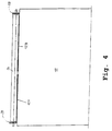
- FIG. 4 shows an illustration of the exemplary embodiment according to Figure 3 seen from the side. It can be seen that the Support rollers 28 have a slightly larger diameter than the pinch roller 26 itself.
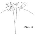
- FIG. 5 shows a further exemplary embodiment of the invention, in which the pressure roller 26 resiliently on a rotary arm 32 the transfer jaw 18 is mounted. Also with this figure same parts are again labeled the same.
- the right transfer jaw 20 has a protruding leading end 34.
- a pressure spring 35 tensions the pressure roller 26 in the direction of the photoconductor drum 10 before. Due to the defined pressure the pressure roller 26 results in a relatively large angle ⁇ in which the recording material 12 is in contact with the surface of the photoconductor drum 10. This large angle ⁇ causes the transfer of toner particles on the recording medium 12 evenly and without distance fluctuations between carrier material 12 and surface of the Photoconductor drum 10 takes place. This way, a high Print quality achieved.
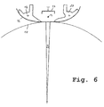
- Figure 6 shows a conventional arrangement for comparison Way, without pinch roller.
- the angle ⁇ at which a touch between record carrier 12 and surface of the Photoconductor drum 10 takes place is significantly reduced.
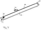
- FIGs 7 to 9 show another advantageous Example of a transfer station, where instead of the Pressure roller a pressure rail 36 is arranged.
- the Pressure rail 36 is part of transfer printing jaws 18, 20 and consists of a polished steel profile with on it trained sliding surface 37 for the record carrier. she extends across the entire width of the writable Area of the consisting of a photoconductor drum 10 Subcarrier.
- Support rollers 28 are arranged which are rubberized on their circumference. They work with corresponding, outside of the real thing Areas of the photoconductor drum arranged in the writing area together. Due to the profile, the pressure rail particularly rigid.
- the pressure rail 36 with the support rollers 28 part of both transfer printing jaws 18, Be 20, so that the record carrier 12 in the area of Transfer point particularly well managed or just Part of the transfer printing jaw 18 that the recording medium to the transfer point. It is also analogous to that Embodiments with pressure roller possible Pressure rail 36 separated from transfer printing jaws 18, 20 to arrange.
- the transfer printing jaws 18 and 20 about axes of rotation 44 pivoted (arrows).
- the tension spring 42 provides on the one hand for contact with the eccentric, in particular when swiveling, on the other hand, it presses over the Pressure rails 36 and their sliding surfaces 37 den Record carrier 12 with a given spring force against Photoconductor drum 12, the support rollers 28 a Prevent falling below the transfer gap.
- the Transfer printing jaws are thus relative to the surface of the Photoconductor drum 12 against the spring force of the spring 42 slidably mounted, so that the record carrier different thicknesses can be processed.
- the invention was based on Described embodiments in which band-shaped Record carriers are used, however, it is at appropriate adaptation can also be used in transfer printing stations, process the single sheets.
Landscapes
- Physics & Mathematics (AREA)
- General Physics & Mathematics (AREA)
- Electrostatic Charge, Transfer And Separation In Electrography (AREA)
Description
- Figur 1
- schematisch den Aufbau einer bekannten Umdruckstation im Umdruckbereich,
- Figur 2
- eine Lösung nach dem Stand der Technik mit einem klingenartigen Andruckelement,
- Figur 3
- ein Ausführungsbeispiel der Erfindung mit Andruckrollen und Stützrollen,
- Figur 4
- eine Ansicht des Aufbaus nach Figur 3 von der Seite her gesehen,
- Figur 5
- ein Ausführungsbeispiel mit auf Federn gelagerten Andruckrollen,
- Figur 6
- einen Vergleich des Andruckwinkels mit dem Stand der Technik,
- Figur 7
- eine schematische Schnittdarstellung einer Ausführungsform einer Umdruckstation mit einer Andruckschiene mit zugehörigen Stützrollen als Teil der Umdruckbacken,
- Figur 8
- eine Teilansicht der Umdruckstation gemäß Figur 7 im Umdruckbereich und
- Figur 9
- eine schematische Darstellung einer Umdruckbacke mit integrierter Andruckschiene und Stützrollen.
- 10
- Zwischenträger, Fotoleitertrommel
- 12, 12A, 12B
- Aufzeichnungsträger
- 14
- Koronadraht
- 16
- Abschirmplatte
- 18, 20
- Umdruckbacken
- 22
- Ende des Umdruckbackens
- 24
- klingenförmiges Andruckelement
- 26
- Andruckrolle
- 28
- Stützrollen
- 30
- Erdung
- 32
- Haltearm
- 34
- Führungsende
- 36
- Andruckschiene
- 37
- Gleitfläche
- 38
- Andruckpunkt der Andruckschiene
- 39
- Andruckpunkt der Andruckrolle
- 40
- Hebelarm
- 41
- Rollen
- 42
- Zugfeder
- 43
- Exzenter, Kurvenscheibe
- 44
- Drehachse Umdruckbacken
Claims (13)
- Umdruckstation für ein elektrografisches Druck- oder Kopiergerät, mit
einer elektrostatischen Umdruckeinrichtung (14) zum Übertragen eines auf einem elektrografischen Zwischenträger (10) erzeugten Tonerbildes auf mindestens einen Aufzeichnungsträger (12) in einem Umdruckbereich der Umdruckstation,
im Umdruckbereich in Laufrichtung des Aufzeichnungsträgers nacheinander angeordneten Führungselementen (18, 20) zum Führen des Aufzeichnungsträgers (12) nahe dem Zwischenträger (10) während des Umdruckvorganges,
mindestens einem zwischen den Führungselementen (18, 20) angeordneten, relativ zum Zwischenträger (10) entgegen einer Federkraft (42) verschieblichen biegesteifen Andruckelement, welches den mindestens einen Aufzeichnungsträger (12) während des Umdruckvorganges gegen den Zwischenträger (10) drückt und
und mit mindestens einem, dem Andruckelement zugeordneten, zur Aufrechterhaltung eines definierten Mindestabstandes zwischen Andruckelement und Zwischenträger (10), sich auf dem Zwischenträger (10) abstützenden Abstandselement (28),
wobei das Andruckelement als Andruckschiene (36) ausgebildet ist. - Umdruckstation nach Anspruch 1, dadurch gekennzeichnet, daß die Andruckschiene (36) aus einem biegesteifen Profil mit darauf angeordneter Gleitfläche (37) besteht.
- Umdruckstation für ein elektrografisches Druck- oder Kopiergerät, mit
einer elektrostatischen Umdruckeinrichtung (14) zum Übertragen eines auf einem elektrografischen Zwischenträger (10) erzeugten Tonerbildes auf mindestens einen Aufzeichnungsträger (12) in einem Umdruckbereich der Umdruckstation,
im Umdruckbereich in Laufrichtung des Aufzeichnungsträgers nacheinander angeordneten zwei Führungselementen (18, 20) zum Führen des Aufzeichnungsträgers (12) nahe dem Zwischenträger (10) während des Umdruckvorganges,
mindestens einem zwischen den Führungselementen (18, 20) angeordneten, relativ zum Zwischenträger (10) entgegen einer Federkraft (42) verschieblichen biegesteifen Andruckelement, welches den mindestens einen Aufzeichnungsträger (12) während des Umdruckvorganges gegen den Zwischenträger (10) drückt und
und mit mindestens einem, dem Andruckelement (26) zugeordneten, zur Aufrechterhaltung eines definierten Mindestabstandes zwischen Andruckelement und Zwischenträger (10), sich auf dem Zwischenträger (10) abstützenden Abstandselement (28),
wobei als Andruckelement eine Andruckrolle (26) vorgesehen ist, die auf dem Aufzeichnungsträger (12) abrollt,
und wobei die Längsachse der Andruckrolle (26) parallel zur Oberfläche des Zwischenträgers (10) verläuft, um die Andruckrolle (26) auf gleichen Abstand zur Oberfläche des Zwischenträgers (10) zu halten. - Umdruckstation nach einem der vorhergehenden Ansprüche 1 bis 3, dadurch gekennzeichnet, daß die Oberfläche des Andruckelementes (26, 36) elektrisch leitend ist und ein vorbestimmtes elektrisches Potential hat.
- Umdruckstation nach einem der vorhergehenden Ansprüche, dadurch gekennzeichnet, daß die Führungselemente als um eine Achse verschwenkbare Umdruckbacken (18, 20) ausgebildet sind, die während des Umdruckvorganges in Richtung des Zwischenträgers (10) geschwenkt und außerhalb des Umdruckvorganges vom Zwischenträger (10) weggeschwenkt sind, und daß mindestens an dem den Aufzeichnungsträger (12) zuführenden Umdruckbacken (18) das Andruckelement (26, 36) angeordnet ist.
- Umdruckstation nach Anspruch 5, dadurch gekennzeichnet, daß jeder Umdruckbacke (18, 20) ein Andruckelement (26, 36) zugeordnet ist.
- Umdruckstation nach einem der Ansprüche 5 oder 6 dadurch gekennzeichnet, daß das Andruckelement (26, 36) Teil einer Umdruckbacke (18, 20) ist.
- Umdruckstation nach einem der vorhergehenden Ansprüche, dadurch gekennzeichnet, daß . das Abstandselement als Stützrolle (28) ausgebildet ist.
- Umdruckstation nach Anspruch 8, dadurch gekennzeichnet, daß jeweils Stützrollen (28) an den Enden des Andruckelementes (26, 36) angeordnet sind und gegebenenfalls auf den äußersten Abschnitten des Zwischenträgers (10) abrollen.
- Umdruckstation nach einem der vorhergehenden Ansprüche, dadurch gekennzeichnet, daß die Länge des Andruckelementes (26), der Führungselemente (18, 20) und des Zwischenträgers (10) so bemessen ist, daß zwei nebeneinanderliegende Bahnen (12A, 12B) von Aufzeichnungssträgern gleichzeitig umgedruckt werden können.
- Umdruckstation nach Anspruch 10, dadurch gekennzeichnet, daß mindestens eine der beiden Bahnen (12A, 12B) bereits einmal einen Umdruckvorgang durchlaufen hat.
- Umdruckstation nach einem der Ansprüche 1 bis 9, dadurch gekennzeichnet, daß der Aufzeichnungsträger (12) als Bahn ausgebildet ist und bereits einmal einen Umdruckvorgang durchlaufen hat.
- Umdruckstation nach einem der vorhergehenden Ansprüche, dadurch gekennzeichnet, daß das Andruckelement (26, 36) federnd gelagert ist und die Federkraft (42) das Andruckelement (26, 36) in Richtung des Zwischenträgers (10) vorspannt.
Applications Claiming Priority (3)
| Application Number | Priority Date | Filing Date | Title |
|---|---|---|---|
| DE19749386A DE19749386C2 (de) | 1997-11-07 | 1997-11-07 | Umdruckstation für ein elektrografisches Gerät mit einer Andruckrolle im Umdruckbereich |
| DE19749386 | 1997-11-07 | ||
| PCT/EP1998/007065 WO1999024876A1 (de) | 1997-11-07 | 1998-11-05 | Umdruckstation für ein elektrografisches gerät mit einem andruckelement im umdruckbereich |
Publications (2)
| Publication Number | Publication Date |
|---|---|
| EP1029259A1 EP1029259A1 (de) | 2000-08-23 |
| EP1029259B1 true EP1029259B1 (de) | 2003-09-17 |
Family
ID=7848022
Family Applications (1)
| Application Number | Title | Priority Date | Filing Date |
|---|---|---|---|
| EP98959849A Expired - Lifetime EP1029259B1 (de) | 1997-11-07 | 1998-11-05 | Umdruckstation für ein elektrografisches gerät mit einem andruckelement im umdruckbereich |
Country Status (4)
| Country | Link |
|---|---|
| US (1) | US6314265B1 (de) |
| EP (1) | EP1029259B1 (de) |
| DE (2) | DE19749386C2 (de) |
| WO (1) | WO1999024876A1 (de) |
Families Citing this family (6)
| Publication number | Priority date | Publication date | Assignee | Title |
|---|---|---|---|---|
| ATE386964T1 (de) | 2001-03-22 | 2008-03-15 | Oce Printing Systems Gmbh | Umdruckstation für ein elektrofotografisches druck- oder kopiergerät |
| DE10125326B4 (de) | 2001-05-23 | 2004-03-18 | OCé PRINTING SYSTEMS GMBH | Einrichtung zur Entfernung eines auf einem Zwischenträger haftenden Belags bei einem elektrografischen Druck- oder Kopiergerät |
| DE10213499B4 (de) | 2002-03-26 | 2005-02-03 | OCé PRINTING SYSTEMS GMBH | Vorrichtung zum Transport von Toner bei einer elektrofotografischen Druck- oder Kopiereinrichtung |
| JP4245325B2 (ja) * | 2002-10-10 | 2009-03-25 | シャープ株式会社 | 転写装置 |
| DE10322502A1 (de) | 2003-05-19 | 2004-12-23 | OCé PRINTING SYSTEMS GMBH | Umdruckstation für ein elektrografisches Druck- oder Kopiergerät |
| JP6240701B2 (ja) | 2016-03-30 | 2017-11-29 | 大王製紙株式会社 | パンツタイプ使い捨ておむつ |
Family Cites Families (11)
| Publication number | Priority date | Publication date | Assignee | Title |
|---|---|---|---|---|
| JPS538146A (en) * | 1976-07-12 | 1978-01-25 | Canon Inc | Transfer mechanism |
| DE2636326C3 (de) * | 1976-08-12 | 1979-02-01 | Siemens Ag, 1000 Berlin Und 8000 Muenchen | Vorrichtung zum An- und Abschwenken eines Aufzeichnungsträgers zu und von einem Zwischenträger |
| US4392738A (en) * | 1978-11-10 | 1983-07-12 | Canon Kabushiki Kaisha | Image transfer device |
| JPS5576367A (en) | 1978-12-01 | 1980-06-09 | Fujitsu Ltd | Transfer device |
| DE69009074T2 (de) * | 1989-02-08 | 1994-10-06 | Toshiba Kawasaki Kk | Übertragungsvorrichtung. |
| US5351114A (en) * | 1991-04-22 | 1994-09-27 | Hitachi, Ltd. | Electrophotographic copying apparatus having ribbon-shaped toner image carrier |
| DE4305686C2 (de) * | 1992-02-24 | 1999-07-15 | Fujitsu Ltd | Tonerbild-Übertragungsvorrichtung einschließlich einer Übertragungsladevorrichtung und einer Wechselspannungs-Ladungslöschvorrichtung |
| JP2798868B2 (ja) * | 1992-11-26 | 1998-09-17 | 三田工業株式会社 | 転写装置 |
| JPH0784468A (ja) | 1993-09-14 | 1995-03-31 | Fuji Xerox Co Ltd | 画像形成装置 |
| DE9314937U1 (de) * | 1993-10-01 | 1993-12-09 | Siemens Nixdorf Informationssysteme Ag, 33102 Paderborn | Umdruckstation mit Andruckelement für ein elektrografisches Druck- oder Kopiergerät |
| DE19541061C1 (de) * | 1995-11-03 | 1996-11-07 | Siemens Nixdorf Inf Syst | Elektrografischer Drucker mit Ausgleichsvorrichtungen |
-
1997
- 1997-11-07 DE DE19749386A patent/DE19749386C2/de not_active Expired - Fee Related
-
1998
- 1998-11-05 EP EP98959849A patent/EP1029259B1/de not_active Expired - Lifetime
- 1998-11-05 DE DE59809663T patent/DE59809663D1/de not_active Expired - Lifetime
- 1998-11-05 WO PCT/EP1998/007065 patent/WO1999024876A1/de not_active Ceased
- 1998-11-05 US US09/530,978 patent/US6314265B1/en not_active Expired - Lifetime
Also Published As
| Publication number | Publication date |
|---|---|
| DE19749386C2 (de) | 2000-02-24 |
| US6314265B1 (en) | 2001-11-06 |
| DE19749386A1 (de) | 1999-05-27 |
| DE59809663D1 (de) | 2003-10-23 |
| WO1999024876A1 (de) | 1999-05-20 |
| EP1029259A1 (de) | 2000-08-23 |
Similar Documents
| Publication | Publication Date | Title |
|---|---|---|
| DE2636326C3 (de) | Vorrichtung zum An- und Abschwenken eines Aufzeichnungsträgers zu und von einem Zwischenträger | |
| DE2909775A1 (de) | Bandspursystem | |
| DE60123901T2 (de) | Aufladungsrolle für ein Bilderzeugungsgerät | |
| DE4324148C2 (de) | Riemen-Übertragungseinrichtung für elektrophotographisches Gerät | |
| DE69715721T2 (de) | Bandreiniger und diesen verwendendes Bilderzeugungsgerät | |
| DE3432189C2 (de) | Fixiervorrichtung | |
| DE3414298A1 (de) | Photoempfindliche trommel | |
| DE69837685T2 (de) | Entwickler für die effiziente Übertragung eines Tonerbildes mit einer Bandzwischenübertragung | |
| DE3850721T2 (de) | Entwicklungsvorrichtung. | |
| DE2528862C2 (de) | Vorrichtung zum Abtragen von überschüssiger Entwickler-Flüssigkeit von einem Aufzeichnungsträger in einem elektrophotografischen Kopiergerät | |
| DE19813205A1 (de) | Reinigungsvorrichtung für eine Bildübertragungsband-Vorrichtung | |
| DE102007003843B4 (de) | Bilderzeugungseinrichtung | |
| DE69014411T2 (de) | Aufzeichnungsgerät. | |
| DE19749386C2 (de) | Umdruckstation für ein elektrografisches Gerät mit einer Andruckrolle im Umdruckbereich | |
| EP0404769A1 (de) | Vorrichtung zum glätten von einzelblättern in nichtmechanischen druck- und kopiereinrichtungen. | |
| EP1241533A2 (de) | Verbesserte Übertragungswalzenreinigung | |
| DE3436648C2 (de) | ||
| DE4112031A1 (de) | Elektrofotografischer drucker mit einer anordnung zum verhindern von schraeglauf | |
| DE19848963C2 (de) | Bandübertragungsvorrichtung für ein Bilderzeugungsgerät | |
| DE69218923T2 (de) | Reinigungsvorrichtung, Bilderzeugungsgerät und -system | |
| DE2646399A1 (de) | Vorschiebbarer photorezeptor | |
| DE69723656T2 (de) | Rolle für primäre Aufladung | |
| EP1370913B1 (de) | Umdruckstation für ein elektrofotografisches druck- oder kopiergerät | |
| DE3604915A1 (de) | Papierfuehrungsvorrichtung fuer einen drucker | |
| DE10041753B4 (de) | Bilderzeugendes Gerät |
Legal Events
| Date | Code | Title | Description |
|---|---|---|---|
| PUAI | Public reference made under article 153(3) epc to a published international application that has entered the european phase |
Free format text: ORIGINAL CODE: 0009012 |
|
| 17P | Request for examination filed |
Effective date: 20000605 |
|
| AK | Designated contracting states |
Kind code of ref document: A1 Designated state(s): BE DE FR GB |
|
| GRAH | Despatch of communication of intention to grant a patent |
Free format text: ORIGINAL CODE: EPIDOS IGRA |
|
| GRAS | Grant fee paid |
Free format text: ORIGINAL CODE: EPIDOSNIGR3 |
|
| GRAA | (expected) grant |
Free format text: ORIGINAL CODE: 0009210 |
|
| AK | Designated contracting states |
Kind code of ref document: B1 Designated state(s): BE DE FR GB |
|
| PG25 | Lapsed in a contracting state [announced via postgrant information from national office to epo] |
Ref country code: FR Free format text: LAPSE BECAUSE OF FAILURE TO SUBMIT A TRANSLATION OF THE DESCRIPTION OR TO PAY THE FEE WITHIN THE PRESCRIBED TIME-LIMIT Effective date: 20030917 |
|
| REG | Reference to a national code |
Ref country code: GB Ref legal event code: FG4D Free format text: NOT ENGLISH |
|
| REF | Corresponds to: |
Ref document number: 59809663 Country of ref document: DE Date of ref document: 20031023 Kind code of ref document: P |
|
| PG25 | Lapsed in a contracting state [announced via postgrant information from national office to epo] |
Ref country code: BE Free format text: LAPSE BECAUSE OF NON-PAYMENT OF DUE FEES Effective date: 20031130 |
|
| GBT | Gb: translation of ep patent filed (gb section 77(6)(a)/1977) |
Effective date: 20031215 |
|
| BERE | Be: lapsed |
Owner name: *OCE PRINTING SYSTEMS G.M.B.H. Effective date: 20031130 |
|
| PLBE | No opposition filed within time limit |
Free format text: ORIGINAL CODE: 0009261 |
|
| STAA | Information on the status of an ep patent application or granted ep patent |
Free format text: STATUS: NO OPPOSITION FILED WITHIN TIME LIMIT |
|
| 26N | No opposition filed |
Effective date: 20040618 |
|
| EN | Fr: translation not filed | ||
| PGFP | Annual fee paid to national office [announced via postgrant information from national office to epo] |
Ref country code: GB Payment date: 20081128 Year of fee payment: 11 |
|
| GBPC | Gb: european patent ceased through non-payment of renewal fee |
Effective date: 20091105 |
|
| PG25 | Lapsed in a contracting state [announced via postgrant information from national office to epo] |
Ref country code: GB Free format text: LAPSE BECAUSE OF NON-PAYMENT OF DUE FEES Effective date: 20091105 |
|
| PGFP | Annual fee paid to national office [announced via postgrant information from national office to epo] |
Ref country code: DE Payment date: 20130130 Year of fee payment: 15 |
|
| REG | Reference to a national code |
Ref country code: DE Ref legal event code: R119 Ref document number: 59809663 Country of ref document: DE |
|
| PG25 | Lapsed in a contracting state [announced via postgrant information from national office to epo] |
Ref country code: DE Free format text: LAPSE BECAUSE OF NON-PAYMENT OF DUE FEES Effective date: 20140603 |
|
| REG | Reference to a national code |
Ref country code: DE Ref legal event code: R119 Ref document number: 59809663 Country of ref document: DE Effective date: 20140603 |