EP1028496A2 - Connecteur électrique avec dispositif de verrouillage et ressort métalique - Google Patents
Connecteur électrique avec dispositif de verrouillage et ressort métalique Download PDFInfo
- Publication number
- EP1028496A2 EP1028496A2 EP00101504A EP00101504A EP1028496A2 EP 1028496 A2 EP1028496 A2 EP 1028496A2 EP 00101504 A EP00101504 A EP 00101504A EP 00101504 A EP00101504 A EP 00101504A EP 1028496 A2 EP1028496 A2 EP 1028496A2
- Authority
- EP
- European Patent Office
- Prior art keywords
- connector
- latch
- shell
- conductive shell
- spring
- Prior art date
- Legal status (The legal status is an assumption and is not a legal conclusion. Google has not performed a legal analysis and makes no representation as to the accuracy of the status listed.)
- Withdrawn
Links
Images


Classifications
-
- H—ELECTRICITY
- H01—ELECTRIC ELEMENTS
- H01R—ELECTRICALLY-CONDUCTIVE CONNECTIONS; STRUCTURAL ASSOCIATIONS OF A PLURALITY OF MUTUALLY-INSULATED ELECTRICAL CONNECTING ELEMENTS; COUPLING DEVICES; CURRENT COLLECTORS
- H01R13/00—Details of coupling devices of the kinds covered by groups H01R12/70 or H01R24/00 - H01R33/00
- H01R13/62—Means for facilitating engagement or disengagement of coupling parts or for holding them in engagement
- H01R13/627—Snap or like fastening
- H01R13/6271—Latching means integral with the housing
- H01R13/6272—Latching means integral with the housing comprising a single latching arm
-
- H—ELECTRICITY
- H01—ELECTRIC ELEMENTS
- H01R—ELECTRICALLY-CONDUCTIVE CONNECTIONS; STRUCTURAL ASSOCIATIONS OF A PLURALITY OF MUTUALLY-INSULATED ELECTRICAL CONNECTING ELEMENTS; COUPLING DEVICES; CURRENT COLLECTORS
- H01R13/00—Details of coupling devices of the kinds covered by groups H01R12/70 or H01R24/00 - H01R33/00
- H01R13/62—Means for facilitating engagement or disengagement of coupling parts or for holding them in engagement
- H01R13/629—Additional means for facilitating engagement or disengagement of coupling parts, e.g. aligning or guiding means, levers, gas pressure electrical locking indicators, manufacturing tolerances
- H01R13/633—Additional means for facilitating engagement or disengagement of coupling parts, e.g. aligning or guiding means, levers, gas pressure electrical locking indicators, manufacturing tolerances for disengagement only
- H01R13/635—Additional means for facilitating engagement or disengagement of coupling parts, e.g. aligning or guiding means, levers, gas pressure electrical locking indicators, manufacturing tolerances for disengagement only by mechanical pressure, e.g. spring force
-
- H—ELECTRICITY
- H01—ELECTRIC ELEMENTS
- H01R—ELECTRICALLY-CONDUCTIVE CONNECTIONS; STRUCTURAL ASSOCIATIONS OF A PLURALITY OF MUTUALLY-INSULATED ELECTRICAL CONNECTING ELEMENTS; COUPLING DEVICES; CURRENT COLLECTORS
- H01R13/00—Details of coupling devices of the kinds covered by groups H01R12/70 or H01R24/00 - H01R33/00
- H01R13/64—Means for preventing incorrect coupling
- H01R13/641—Means for preventing incorrect coupling by indicating incorrect coupling; by indicating correct or full engagement
Definitions
- the present invention generally relates to the art of electrical connectors and more particularly relates to a mated plug and receptacle having a locking mechanism.
- a plug connector wherein a shield is mounted to provide a predetermined gap around a periphery of terminals, the shield forming a contact with a mated socket connector, as disclosed in Japanese Examined Utility Model Application No. Hei 7-16312.
- the shield is constructed by forming a thin metal plate into an oblate rectangular shape in cross section. The resulting shield is intended to maintain physical contact strength between the connector and the socket by virtue of the spring elasticity of the metal of the shield frame.
- Such known connectors generally include no lock mechanism. Therefore, the plug connector can be easily removed from the receptacle simply by pulling the connector body of the plug connector in a withdrawal direction away from the socket connector.
- Such a non-locking connector arrangement may be sufficient for many personal consumer uses, such as a cable connection between a home personal computer and a digital video, wherein the inserting and withdrawal of the plug is frequently repeated.
- the non-locking arrangement may be insufficient to keep a satisfactory engagement in other environments which demand high reliability, and especially where the removal of the plug is not frequent.
- a more reliable connection is desirable in commercial or business use, such as for a security camera in a bank or a store.
- a connector is needed which is releasably lockable to prevent inadvertent unpluging.
- a connector is needed which provides a robust and stable connection.
- a plug connector having a shield with locking mechanism.
- the locking mechanism includes a movable latch, the latch including a claw that projects outwardly from a side of the shield.
- a mated socket receptacle is also provided for receiving the plug connector. Upon plugging the plug connector into a mated socket receptacle, the projecting claw is received into a corresponding engagement recess formed in the socket receptacle.
- the plug connector may be able to move relative to the socket receptacle at the side opposite the single locking mechanism. From such movement, there is a possibility that the projection can work free from the recess, unlocking the connector. In order to prevent this, it has been considered to provide a connector with a pair of lock mechanisms on opposite sides. However, providing multiple locks on the connector unduly complicates the structure, raising manufacturing costs. Additionally, a dual-lock connector structure can lead to a rattle or wobble due to the fine positional displacement of the lock mechanisms. If such rattle is generated, the electrical connection between the shield and the receptacle is unstable.
- features of the present invention enable a connector structure having a single locking mechanism to provide a stable connection and securely locked fit between the plug and socket receptacle. Additionally, the present invention advantageously reduces noise components upon the connection to the socket.
- An additional feature of the invention is that it produces "click” or frictional feeling when the latch is pressed by a user.
- the structure of the connector is set so that the click corresponds to a depressed, unlocked condition of the claw relative to the recess in the socket receptacle.
- This sensory feedback is helpful to a person operating the plug, as it advantageously indicates that the plug can be withdrawn.
- this click effect is performed by the latch spring.
- the latch spring is formed in a folded-over leaf shape such that two free ends of the spring are normally separated by a small gap, but as the spring is deflected as the latch is depressed, the two free ends of the spring physically contact each other and then pass over each other with slight interference.
- the spring according to this embodiment of the invention performs both the lock release "click" indicator function and the inherent spring function to bias the latch.
- a shielded electrical connector having an insulative housing containing a plurality of terminal cavities, a plurality of terminals loaded into respective terminal cavities, and a conductive shell enclosing a portion of the housing.
- the conductive shell has a front opening to provide access for a mating connector. Additionally, a first side of the conductive shell has a first aperture and a second aperture.
- a latch disposed on the shell has a rear end pivotally mounted to shell. The latch further includes a push portion accessible through the second aperture in the shell and a claw projecting outwardly through the first aperture in the shell.
- a spring is disposed between the shield and latch for biasing the latch, and claw, outwardly.
- the connector further includes an inner shield that encloses the housing within the conductive shell.
- latch For pivotally mounting to the shell, in an embodiment, latch includes a pair of oppositely-directed posts that pivotally reside in pivot holes in the shell.
- the connector additionally includes an insulative jacket around the conductive shell.
- This jacket is preferably formed of a flexible material, such as a rubber or plastic material.
- the insulative jacket includes a flexible press portion abutting against the push portion of the latch.
- the insulative jacket protects the other components of the connector and allows the connector to be easily gripped while permitting manipulation of the latch.
- the latch is disposed between the conductive shell and the insulative jacket around the shell.
- the connector includes a biasing spring outwardly projecting from a second side of the shell. This biasing spring advantageously ensures a secure fit of the connector within a mated socket receptacle and a stable grounding connection.
- the receptacle connector includes a pushing spring that is biased against a face of the plug connector upon insertion, applying a force against the plug connector in the withdraw direction.
- This pushing spring advantageously keeps a side of the deployed claw held firmly against the recess in the socket receptacle, enhancing the locking action of the claw. Additionally, when the latch is depressed to release the plug connector, retracting the claw from the recess, the pushing spring advantageously boosts the plug connector in a withdrawal direction from the receptacle connector.
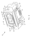
- FIG. 1 is a perspective view of an electrical plug connector with a lock mechanism in accordance with an embodiment of the present invention.
- FIG. 2 is a perspective view of the electric connector of FIG. 1 as viewed from above another angle.
- FIG. 3 is a cross-sectional view of the connector of FIGS. 1 and 2.
- FIG. 4 is a plan view of a spring of the connector.
- FIG. 5 is a side elevational view of the spring.
- FIG. 6 is a base view of the spring.
- FIG. 7 is an enlarged fragmentary view of a the area of the spring indicated by circle A of FIG. 5.
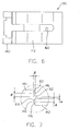
- FIG. 8 is a perspective view of a complementary socket connector.
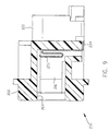
- FIG. 9 is a cross-sectional of the socket connector as taken generally along line IX-IX of FIG. 8.
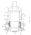
- FIG. 10 is a partially sectional plan view, showing a grounded connector assembly including the plug connector mated with the socket connector.
- FIGS. 1-3 illustrate a plug connector 100 embodying features in accordance with teachings of the present invention.
- the illustrated connector 100 is a 1394-type connector, however, the present invention can be used with other types of connectors also.
- FIGS. 8 and 9 illustrate a corresponding socket connector 200 for matably receiving the plug connector 100.
- the plug connector 100 and socket connector 200 are illustrated in a mated condition in FIG. 10.
- the plug connector 100 includes an insulative housing 102.
- an conductive inner shield 104 is disposed peripherally around the housing 102.
- the housing 102 contains a plurality of terminal cavities which hold a plurality of respective conductive terminals 106.
- a terminal opening 108 is formed in the housing 102 for providing access to the terminals 106.
- An intermediate housing 109 ( Figure 3) is disposed outside of the inner shield.
- a cable 110 for example a coaxial cable, is mounted to a rear of the housing 102 for delivering a signal or power to or from the connector 100.
- the cable 110 contains conductive leads which are connected to the respective terminals 106.
- the plug connector 100 includes a conductive shell 112, shown in FIGS. 1-3, which encloses a portion of the housing 102.
- An forward insertion portion 114 of the shell 112 has a front opening to provide access for the socket connector 200 (FIGS. 8-10).
- a gap 113 is separates the conductive shell 110 and the housing 102.
- the conductive shell 112 is rigid and may be formed from a metal such as aluminum by die-casting or machining.
- the shell 112 preferably comprises a top component juxtaposed with a bottom component.
- the connector 100 additionally includes an insulative jacket 116 disposed exteriorly around the conductive shell 112.
- the jacket 116 is formed of a flexible material, such as a molded synthetic resin.
- the insertion portion 114 of the shell 112 extends forwardly of the jacket 116 to permit proper mated insertion with the socket receptacle 200 (FIGS. 8-10).
- the plug connector 100 includes a movable latch 120, as illustrated in FIG. 3.
- the latch 120 is disposed between the housing 102 and the shell 112.
- a forward portion of the latch 120 forms a claw 122 that projects outwardly through a first aperture in the shell 112, as illustrated also in FIG. 1.
- a rear end of the latch 120 is movably mounted to the shell 112 at a pivot 124.
- pivot 124 includes a pair of oppositely-directed posts that extend from opposite sides of the latch 120 and pivotally reside in corresponding pivot holes in the shell 112. Extending forwardly from the pivot 124, the latch 120 has a push portion 126 accessible through a second aperture in the shell 112.
- the latch 120 is formed of a rigid material, such as metal or hard plastic.
- the latch 120 is movable on said pivot relative to the shell 112 to move the claw 122 selectively between an extended position, as illustrated in FIGS. 1 and 3, and a retracted position, wherein the claw 122 retracts through the corresponding aperture in the shell 112.
- the claw 112 is ramp-shaped for one-way locking insertion.
- a latch spring 130 is disposed on the shell 112 between an outer wall of shield 112 and the latch 120 for normally biasing the latch 120 outwardly. The latch spring 130 is described in greater detail below in connection with FIGS. 4-7.
- the jacket 116 preferably includes a press portion 132 that lies over the push portion of the latch, the press portion 132 of the jacket being defined by slots 134 for added flexibility.
- the illustrated embodiment of the plug connector 100 includes a grounding spring 136 having a projecting portion 138 that normally projects from a recess 139 on an opposite side of the shell 112.
- the projecting portion 138 of the grounding spring 136 retracts into the recess 139 when met by a sliding force in the insertion direction exerted by the socket connector 200 upon mating, but maintains an outward bias.
- the latch spring 130 is unitarily formed in a folded-over shape, having a first leaf 140 on one side, a second leaf 142 on the other side, joined by a U-shaped bend 144 (FIG. 5), and having a pair of respective free ends 146 and 148.
- the spring 130 provides a convenient "click” or friction feeling corresponding to a retracted position of the locking claw 122 when the latch 120 (FIG. 3) is pressed by a user. This "click" feedback indicates to the user that the latch is released and that the plug connector 100 may be withdrawn.
- the free ends 146, 148 of the latch spring 130 are directed generally toward each, but are slightly offset relative to each other.
- FIG. 7 is an enlarged view of the portion A of FIG. 5, illustrating the normal offset position of the free ends 146, 148 in greater detail, the free ends 146, 148 being slightly separated by a suitable gap a in an expansion/contraction direction.
- each of the free ends 146, 148 is tapered or crested in shape. More specifically, the free end 146 includes tapered surfaces 150 and 152, and the free end 148 includes tapered surfaces 154 and 156.
- the free ends 146, 148 overlap each other in an overlap dimension ⁇ , so that when the latch 120 (FIG. 3) is pressed, deflecting the spring 130, the free ends 146 and 148 move toward each other and contact against each other.
- the overlap dimension ⁇ is selected so that the continued deflection of the latch spring 130 causes the free ends 146, 148 to pass over each other with the desired slight frictional interference or "click."
- the tapered surfaces 150, 152, 154, 156 assist the free ends 146, 148 to ride over each other.
- a suitable latch spring 130 may have a plate thickness ( ⁇ x2) of about 0.2 mm, the overlap length ⁇ is about 0.05 mm and the gap ⁇ is set at about 0.07 mm.
- the latch spring 130 is formed of resilient spring metal.
- the bias force of the latch spring 130 can be adjusted by cutting material from the spring 130.
- an oblong slot 160 is formed in the intermediate portion in the width direction the spring leaf 142.
- cutaway slots 162 may be formed on both sides in the width direction of the other spring leaf 140, to adjust the overall spring force as needed to provide a desired amount of resistance.
- the socket connector 200 includes an insulative socket body 202 defining an insertion port 204 at a front thereof shaped to receive the insertion portion 114 of the plug connector 100 (FIGS. 1-3).
- the socket body 202 forms guide sleeve 206 which projects forwardly within the insertion port 204, the guide sleeve 206 being shaped to fit within the a gap 113 of the plug connector 100 (FIGS. 1-3) and to receive the forward portion of the housing 102 of the plug connector 100.
- the socket body 202 defines a plurality of terminal cavities which hold a plurality of conductive terminals 208.
- the socket body includes a terminal platform 210 which projects forwardly within the guide sleeve 206 and on which contact portions of the terminals 208 are disposed.
- the terminal platform 210 is shaped to be received within terminal opening 108 of the plug connector 100 (FIGS. 1 and 2) so that the terminals 208 of the socket connector 200 contact the plug terminals 106.
- Tail portions 212 of the conductive terminals 208 project from a rear of the socket body 202 for connection to corresponding conducive pads on a circuit board.
- the socket connector 200 may be molded from a synthetic resin.
- an inner shield 214 is disposed within the guide sleeve 206.
- the inner shield 214 comes into multi-surface contact with the inner shield 104 of the plug connector (FIGS. 1 and 2).
- a recess 216 is provided in the socket body 202 at a position to lockably receive the locking claw 122 of the plug connector 100 (FIGS. 1-3).
- Another recess 218 is provided in the socket body 202 at an opposite side of the insertion port 204 to receive the grounding spring 136, as illustrated in FIG. 10.
- a portion of a conductive shield may be disposed in the recess 216 and/or 218.
- the claw 122 and grounding spring 136 each can serve to provide grounding contact between the plug connector 100 and the socket connector 200.
- a protuberance 220 is preferably formed on an inner surface of the above-described inner shield 214 at a position that serves as a pivot point when the external force is applied against the plug 100 when mated with the socket 200. In such a condition, it is also possible to keep a contact stability between the inner shield 104 of the plug connector 100 and the inner shield 214.
- the socket body 202 forms mounting blocks 222 and 224 at opposite sides.
- a pair of screw apertures 226 may be provided in the socket body 202 in the insertion direction for securely mounting the socket connector 200.
- a pair of screw apertures 228 may be provided in a perpendicular direction.
- the socket connector 200 may be mounted to a panel or on a circuit board.
- the socket body 202 is mounted on a circuit board (not shown) using a pair of screws 230 extending through the screw apertures 228.
- the socket connector 200 includes serpentine pushing springs 232.
- Each of the pushing springs 232 is mounted generally in the deepest portion of the insertion port 204.
- These springs 232 are preferably formed by bending a conductive metal plate into a Z-shape or serpentine shape.
- a front face of the plug connector 100 is brought into contact with the pushing springs 232 so that the pushing springs 232 bias against the plug connector 100 in the removal direction. As shown in FIGS.
- a respective contact end 234 of each of the above-described pushing springs is bent in an L-shape and projects from the bottom surface of the above-described socket body 202.
- the spring ends 234 may be connected to a ground contact (not shown) of the circuit board by soldering or the like. This advantageously provides stable grounding to both the socket connector 200 and the plug connector 100 as enhanced by the grounding contact as a result of the claw 122 and the grounding spring 136 in grounding contact with grounded portions of the socket connector 200.
Applications Claiming Priority (4)
| Application Number | Priority Date | Filing Date | Title |
|---|---|---|---|
| JP01683799A JP4074022B2 (ja) | 1999-01-26 | 1999-01-26 | シールドコネクタ |
| JP1683799 | 1999-01-26 | ||
| JP15248499A JP4191321B2 (ja) | 1999-05-31 | 1999-05-31 | ロック機構付き電気コネクタ及び金属製スプリング |
| JP15248499 | 1999-05-31 |
Publications (2)
| Publication Number | Publication Date |
|---|---|
| EP1028496A2 true EP1028496A2 (fr) | 2000-08-16 |
| EP1028496A3 EP1028496A3 (fr) | 2002-01-30 |
Family
ID=26353267
Family Applications (1)
| Application Number | Title | Priority Date | Filing Date |
|---|---|---|---|
| EP00101504A Withdrawn EP1028496A3 (fr) | 1999-01-26 | 2000-01-26 | Connecteur électrique avec dispositif de verrouillage et ressort métalique |
Country Status (5)
| Country | Link |
|---|---|
| US (1) | US6280227B1 (fr) |
| EP (1) | EP1028496A3 (fr) |
| CN (1) | CN1204659C (fr) |
| SG (1) | SG109416A1 (fr) |
| TW (1) | TW447796U (fr) |
Cited By (4)
| Publication number | Priority date | Publication date | Assignee | Title |
|---|---|---|---|---|
| GB2383202A (en) * | 2001-12-17 | 2003-06-18 | Anthony Brotherton Ratcliffe | Locking electrical connector |
| EP1484822A1 (fr) * | 2003-06-03 | 2004-12-08 | Delphi Technologies, Inc. | Connecteur |
| CH711546A1 (en) * | 2015-09-17 | 2017-03-31 | A Steffen Ag Elektrohandel | Mechanical protection of an electrical connector. |
| EP3392983A4 (fr) * | 2015-12-18 | 2019-08-07 | Hirose Electric Co., Ltd. | Connecteur |
Families Citing this family (32)
| Publication number | Priority date | Publication date | Assignee | Title |
|---|---|---|---|---|
| TWI254498B (en) * | 2001-08-02 | 2006-05-01 | Hosiden Corp | Plug connector |
| TW551718U (en) * | 2002-05-30 | 2003-09-01 | Hon Hai Prec Ind Co Ltd | Electrical connector |
| US6722912B2 (en) * | 2002-07-31 | 2004-04-20 | Hon Hai Precision Ind. Co. Ltd. | Electrical connector having a latch mechanism |
| US8109883B2 (en) | 2006-09-28 | 2012-02-07 | Tyco Healthcare Group Lp | Cable monitoring apparatus |
| JP4278673B2 (ja) * | 2006-10-17 | 2009-06-17 | ヒロセ電機株式会社 | 電気コネクタ |
| US8668651B2 (en) | 2006-12-05 | 2014-03-11 | Covidien Lp | ECG lead set and ECG adapter system |
| CA2646037C (fr) | 2007-12-11 | 2017-11-28 | Tyco Healthcare Group Lp | Connecteur d'electrode pour ecg |
| DE102008006433B4 (de) * | 2008-01-28 | 2011-07-28 | Airbus Operations GmbH, 21129 | Vorrichtung zur Befestigung eines Flugzeugkabinenmoduls |
| WO2009145457A1 (fr) * | 2008-04-01 | 2009-12-03 | Ls Cable Ltd. | Elément élastique et ensemble de connecteurs blindé comportant cet élément |
| USD737979S1 (en) | 2008-12-09 | 2015-09-01 | Covidien Lp | ECG electrode connector |
| US8694080B2 (en) | 2009-10-21 | 2014-04-08 | Covidien Lp | ECG lead system |
| WO2011107075A2 (fr) | 2010-03-01 | 2011-09-09 | Franz Binder Gmbh + Co. Elektrische Bauelemente Kg | Procédé de production d'une interface électrique et interface correspondante |
| CA2746944C (fr) | 2010-07-29 | 2018-09-25 | Tyco Healthcare Group Lp | Systeme adaptateur pour ecg et methode connexe |
| CN202009112U (zh) * | 2011-01-25 | 2011-10-12 | 富士康(昆山)电脑接插件有限公司 | 电连接器组件 |
| CN102801050B (zh) * | 2011-05-23 | 2015-09-09 | 富士康(昆山)电脑接插件有限公司 | 线缆连接器 |
| CN102842813B (zh) * | 2011-06-20 | 2015-02-04 | 富士康(昆山)电脑接插件有限公司 | 电连接器及对接连接器 |
| CN103687537B (zh) | 2011-07-22 | 2016-02-24 | 柯惠有限合伙公司 | Ecg电极连接器 |
| US8634901B2 (en) | 2011-09-30 | 2014-01-21 | Covidien Lp | ECG leadwire system with noise suppression and related methods |
| JP5815424B2 (ja) * | 2012-01-17 | 2015-11-17 | 矢崎総業株式会社 | 電気コネクタ |
| JP5798934B2 (ja) * | 2012-01-17 | 2015-10-21 | 矢崎総業株式会社 | 電気コネクタ |
| JP5927703B2 (ja) * | 2012-11-15 | 2016-06-01 | ヒロセ電機株式会社 | コネクタ装置及びそれに用いるコネクタ |
| US8936497B2 (en) | 2013-02-26 | 2015-01-20 | International Business Machines Corporation | Connector with a rotatably coupled cam shaft having a connect-assist element |
| US9408546B2 (en) | 2013-03-15 | 2016-08-09 | Covidien Lp | Radiolucent ECG electrode system |
| WO2014149548A1 (fr) | 2013-03-15 | 2014-09-25 | Covidien Lp | Connecteur d'électrode à élément conducteur |
| USD771818S1 (en) | 2013-03-15 | 2016-11-15 | Covidien Lp | ECG electrode connector |
| CN103545636B (zh) * | 2013-10-31 | 2016-01-20 | 维尔斯电子(昆山)有限公司 | 锁固式插头连接器 |
| CN103633490B (zh) * | 2013-11-28 | 2015-09-30 | 四川航天计量测试研究所 | 一种无锁紧组件的连接器可靠插接机构及其装配方法和对接方法 |
| CN107172837B (zh) * | 2016-03-08 | 2024-02-20 | 泰科电子(上海)有限公司 | 电子器件安装座、电子器件安装座组件、电器座及电器盒组件 |
| CN107732552A (zh) * | 2017-06-11 | 2018-02-23 | 贵州大学 | 一种贴板焊接电连接器 |
| CN110120612B (zh) * | 2019-04-26 | 2024-05-07 | 桂林航天工业学院 | 一种防松动连接器 |
| CN114665323B (zh) * | 2022-02-23 | 2023-09-26 | 中航光电科技股份有限公司 | 卫星在轨对接用浮动连接器及浮动插座 |
| CN114670149B (zh) * | 2022-03-31 | 2023-07-21 | 华能伊敏煤电有限责任公司 | 一种带有阻尼的叶轮拆除装置 |
Citations (7)
| Publication number | Priority date | Publication date | Assignee | Title |
|---|---|---|---|---|
| US4699438A (en) * | 1985-11-28 | 1987-10-13 | Hirose Electric Co., Ltd. | Locking mechanism for electrical connector |
| US4838810A (en) * | 1987-04-30 | 1989-06-13 | Hirose Electric Co, Ltd. | Coupling engagement mechanism for electric connector |
| US5167523A (en) * | 1991-11-01 | 1992-12-01 | Harbor Electronics, Inc. | Electrical connector |
| EP0562311A2 (fr) * | 1992-03-25 | 1993-09-29 | Hosiden Corporation | Connecteur électrique multipolaire à fiches |
| US5340329A (en) * | 1992-02-28 | 1994-08-23 | Honda Tsushin Kogyo Kabushiki Kaisha | Connector combination |
| US5564939A (en) * | 1992-11-19 | 1996-10-15 | Fujitsu Limited | Connector having a latch mechanism |
| US5749746A (en) * | 1995-09-26 | 1998-05-12 | Hon Hai Precision Ind. Co., Ltd. | Cable connector structure |
Family Cites Families (14)
| Publication number | Priority date | Publication date | Assignee | Title |
|---|---|---|---|---|
| US4516815A (en) * | 1982-06-07 | 1985-05-14 | Spectrum Control, Inc. | RF filter connector |
| US4641902A (en) | 1985-11-13 | 1987-02-10 | E. I. Du Pont De Nemours And Company | Shielded connector with latches |
| JPS63155572A (ja) * | 1986-12-12 | 1988-06-28 | アンプ インコ−ポレ−テツド | シ−ルドコネクタ |
| GB2243029B (en) | 1990-04-12 | 1994-04-06 | Technophone Ltd | Electrical connector |
| GB2244181B (en) * | 1990-04-13 | 1994-12-21 | Oki Electric Cable | Double lock male/female type connector |
| US5154629A (en) * | 1990-08-08 | 1992-10-13 | Icontec, Inc. | Energy transmission cable connector with latching mechanism |
| JPH04108509U (ja) | 1991-03-06 | 1992-09-18 | フクダ電子株式会社 | 誘導コネクタ |
| US5545052A (en) | 1992-08-19 | 1996-08-13 | Honda Tsushin Kogyo Kabushiki Kaisha | Electrical connector |
| US5449298A (en) | 1994-06-30 | 1995-09-12 | The Whitaker Corporation | Latching system for intermatable connectors |
| US5486117A (en) | 1994-08-09 | 1996-01-23 | Molex Incorporated | Locking system for an electrical connector assembly |
| US5533908A (en) | 1994-08-31 | 1996-07-09 | The Whitaker Corporation | Latch and mounting member for a surface mounted electrical connector |
| JP2757139B2 (ja) * | 1995-04-04 | 1998-05-25 | 日本航空電子工業株式会社 | シールド型コネクタ |
| US5816841A (en) * | 1995-04-11 | 1998-10-06 | Acs Wireless, Inc. | Electrical disconnect for telephone headset |
| DE69525623T2 (de) | 1995-08-26 | 2003-03-06 | Molex Inc | Elektrischer Verbinder mit verbessertem Verriegelungssystem |
-
2000
- 2000-01-25 CN CN00104552.0A patent/CN1204659C/zh not_active Expired - Fee Related
- 2000-01-25 SG SG200000428A patent/SG109416A1/en unknown
- 2000-01-26 US US09/492,017 patent/US6280227B1/en not_active Expired - Lifetime
- 2000-01-26 EP EP00101504A patent/EP1028496A3/fr not_active Withdrawn
- 2000-02-22 TW TW089201273U patent/TW447796U/zh unknown
Patent Citations (7)
| Publication number | Priority date | Publication date | Assignee | Title |
|---|---|---|---|---|
| US4699438A (en) * | 1985-11-28 | 1987-10-13 | Hirose Electric Co., Ltd. | Locking mechanism for electrical connector |
| US4838810A (en) * | 1987-04-30 | 1989-06-13 | Hirose Electric Co, Ltd. | Coupling engagement mechanism for electric connector |
| US5167523A (en) * | 1991-11-01 | 1992-12-01 | Harbor Electronics, Inc. | Electrical connector |
| US5340329A (en) * | 1992-02-28 | 1994-08-23 | Honda Tsushin Kogyo Kabushiki Kaisha | Connector combination |
| EP0562311A2 (fr) * | 1992-03-25 | 1993-09-29 | Hosiden Corporation | Connecteur électrique multipolaire à fiches |
| US5564939A (en) * | 1992-11-19 | 1996-10-15 | Fujitsu Limited | Connector having a latch mechanism |
| US5749746A (en) * | 1995-09-26 | 1998-05-12 | Hon Hai Precision Ind. Co., Ltd. | Cable connector structure |
Cited By (8)
| Publication number | Priority date | Publication date | Assignee | Title |
|---|---|---|---|---|
| GB2383202A (en) * | 2001-12-17 | 2003-06-18 | Anthony Brotherton Ratcliffe | Locking electrical connector |
| GB2383202B (en) * | 2001-12-17 | 2005-05-25 | Anthony Brotherton Ratcliffe | Locking connector |
| EP1484822A1 (fr) * | 2003-06-03 | 2004-12-08 | Delphi Technologies, Inc. | Connecteur |
| EP1585201A1 (fr) * | 2003-06-03 | 2005-10-12 | Delphi Technologies, Inc. | Connecteur |
| US7077703B2 (en) | 2003-06-03 | 2006-07-18 | Delphi Technologies, Inc | Plug connector |
| CH711546A1 (en) * | 2015-09-17 | 2017-03-31 | A Steffen Ag Elektrohandel | Mechanical protection of an electrical connector. |
| EP3392983A4 (fr) * | 2015-12-18 | 2019-08-07 | Hirose Electric Co., Ltd. | Connecteur |
| US10454220B2 (en) | 2015-12-18 | 2019-10-22 | Hirose Electric Co., Ltd. | Connector |
Also Published As
| Publication number | Publication date |
|---|---|
| EP1028496A3 (fr) | 2002-01-30 |
| US6280227B1 (en) | 2001-08-28 |
| TW447796U (en) | 2001-07-21 |
| CN1204659C (zh) | 2005-06-01 |
| SG109416A1 (en) | 2005-03-30 |
| CN1264937A (zh) | 2000-08-30 |
Similar Documents
| Publication | Publication Date | Title |
|---|---|---|
| US6280227B1 (en) | Electrical connector with locking mechanism and metal spring | |
| JP2887579B2 (ja) | ロック式電気コネクタとその製造方法 | |
| US10236628B2 (en) | Connector | |
| US5538437A (en) | Connector assembly for IC card | |
| US5775931A (en) | Electrical connector latching system | |
| JP3405954B2 (ja) | コネクタのロック構造 | |
| JP2907373B2 (ja) | コネクタのロック結合検知構造 | |
| US6179643B1 (en) | Connector lock mechanism | |
| US6976865B2 (en) | Cable end connector assembly having pull mechanism | |
| US7445486B2 (en) | Electrical connector with improved latching devices | |
| US6386898B1 (en) | Connector fitting construction | |
| US6027364A (en) | Connector fitting construction with side ribs and corresponding side rib-receiving portions | |
| JP2003243093A (ja) | Usbコネクタ | |
| US6149450A (en) | Smart card adapter latch | |
| US7854618B2 (en) | Wire connector system with lock mechanism | |
| US4906204A (en) | Electrical connector with connector position assurance device | |
| US6773293B1 (en) | Cable end connector with locking member | |
| US6497585B2 (en) | Half-fitting prevention connector | |
| US6276958B1 (en) | Flexible printed circuit connector with a reliably anchored slider | |
| JPS6253910B2 (fr) | ||
| KR100323563B1 (ko) | 로킹 기구 및 금속 스프링을 갖는 전기 커넥터 | |
| US5320546A (en) | Electrical connector with interlocked components | |
| EP1137116A2 (fr) | Système de verrouillage pour connecteurs électriques | |
| KR20010062541A (ko) | 전기 커넥터 조립체 | |
| JP3417846B2 (ja) | シールド部材を有するコネクタ |
Legal Events
| Date | Code | Title | Description |
|---|---|---|---|
| PUAI | Public reference made under article 153(3) epc to a published international application that has entered the european phase |
Free format text: ORIGINAL CODE: 0009012 |
|
| AK | Designated contracting states |
Kind code of ref document: A2 Designated state(s): DE FR GB IT Kind code of ref document: A2 Designated state(s): AT BE CH CY DE DK ES FI FR GB GR IE IT LI LU MC NL PT SE |
|
| AX | Request for extension of the european patent |
Free format text: AL;LT;LV;MK;RO;SI |
|
| PUAL | Search report despatched |
Free format text: ORIGINAL CODE: 0009013 |
|
| AK | Designated contracting states |
Kind code of ref document: A3 Designated state(s): AT BE CH CY DE DK ES FI FR GB GR IE IT LI LU MC NL PT SE |
|
| AX | Request for extension of the european patent |
Free format text: AL;LT;LV;MK;RO;SI |
|
| AKX | Designation fees paid |
Free format text: DE FR GB IT |
|
| STAA | Information on the status of an ep patent application or granted ep patent |
Free format text: STATUS: THE APPLICATION IS DEEMED TO BE WITHDRAWN |
|
| 18D | Application deemed to be withdrawn |
Effective date: 20020731 |