EP1026535B1 - Optische Vorrichtung mit magnetisch betriebenen Mikroverschlüssen oder Mikrospiegeln - Google Patents
Optische Vorrichtung mit magnetisch betriebenen Mikroverschlüssen oder Mikrospiegeln Download PDFInfo
- Publication number
- EP1026535B1 EP1026535B1 EP00830064A EP00830064A EP1026535B1 EP 1026535 B1 EP1026535 B1 EP 1026535B1 EP 00830064 A EP00830064 A EP 00830064A EP 00830064 A EP00830064 A EP 00830064A EP 1026535 B1 EP1026535 B1 EP 1026535B1
- Authority
- EP
- European Patent Office
- Prior art keywords
- substrate
- laminas
- micro
- optical device
- shutters
- Prior art date
- Legal status (The legal status is an assumption and is not a legal conclusion. Google has not performed a legal analysis and makes no representation as to the accuracy of the status listed.)
- Expired - Lifetime
Links
Images
Classifications
-
- G—PHYSICS
- G02—OPTICS
- G02B—OPTICAL ELEMENTS, SYSTEMS OR APPARATUS
- G02B26/00—Optical devices or arrangements for the control of light using movable or deformable optical elements
- G02B26/08—Optical devices or arrangements for the control of light using movable or deformable optical elements for controlling the direction of light
- G02B26/0816—Optical devices or arrangements for the control of light using movable or deformable optical elements for controlling the direction of light by means of one or more reflecting elements
- G02B26/0833—Optical devices or arrangements for the control of light using movable or deformable optical elements for controlling the direction of light by means of one or more reflecting elements the reflecting element being a micromechanical device, e.g. a MEMS mirror, DMD
- G02B26/085—Optical devices or arrangements for the control of light using movable or deformable optical elements for controlling the direction of light by means of one or more reflecting elements the reflecting element being a micromechanical device, e.g. a MEMS mirror, DMD the reflecting means being moved or deformed by electromagnetic means
-
- G—PHYSICS
- G02—OPTICS
- G02B—OPTICAL ELEMENTS, SYSTEMS OR APPARATUS
- G02B26/00—Optical devices or arrangements for the control of light using movable or deformable optical elements
- G02B26/02—Optical devices or arrangements for the control of light using movable or deformable optical elements for controlling the intensity of light
Definitions
- the present invention relates to an optical device with micro-shutters or micro-mirrors.
- the said electrostatic actuators make use of electrically conductive flexible laminas, each of which has one end associated to a stator and the opposite end adjacent to a translator.
- the application of voltage pulses between the laminas and an electrode associated to the translator causes adhesion by electrostatic effect of the laminas to the translator, with the consequent movement of the latter with respect to the stator.
- a matrix of laminas in the form of optical micro-mirrors or micro-shutters, is arranged on a substrate, each lamina being connected at one end to the substrate and being displaceable by electrostatic effect between a resting condition in which it is curved, so that the free end of the lamina is at a distance from the substrate, and a straightened-out condition in which the lamina adheres to the substrate.
- each lamina from the resting condition to the straightened-out condition is obtained by the application of voltage between the lamina and an electrode associated to it which is carried by the substrate.
- the lamina adheres to the substrate by electrostatic effect, whereas when the voltage is interrupted, the lamina returns to its resting condition owing to its own elasticity.
- the purpose of the present invention is to propose a new type of optical device with micro-shutters or micro-mirrors which is based upon a different operating principle.
- an optical device with micro-shutters or micro-mirrors comprising:
- the laminas are made of a material chosen from among nickel, iron, superelastic alloys, and ferromagnetic polymers.
- the laminas may function in a passive way, i.e., be polarized and move owing to an external magnetic field obtained with electromagnets positioned in such a way as to control the field in a point-wise or uniform way so as to enable control of the laminas selectively or control of all the laminas simultaneously.
- the laminas may be used in an active way to generate a magnetic field by being traversed by an electric current.
- the interaction with the material of the substrate - which may consist of ferromagnetic material, or be a permanent magnet, or be equipped with electromagnet means - enables the position of the laminas to be controlled, also in a selective way, according to rows and columns.
- One of the advantages of the device according to the invention as compared to a device with electrostatically operated laminas lies in the fact that the magnetic field can be used both to activate the laminas from the resting, i.e. curved, condition to the straightened-out condition, where the laminas adhere to the substrate, and to push them in the reverse direction, in that it is sufficient, for this purpose, to control the activating magnetic field accordingly.
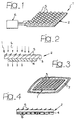
- the reference number 1 designates, as a whole, a matrix of ferromagnetic micro-shutters according to the invention.
- the device 1 comprises a substrate 2, which, in the case illustrated, consists of a glass lamina or plastic lamina 3 that is transparent to light, in the desired wave band, and has a thickness of a few millimetres or centimetres.
- a layer 4 of paramagnetic material On the bottom surface of the substrate 3 is applied a layer 4 of paramagnetic material.
- a plurality of laminas made of ferromagnetic material chosen from among materials such as nickel, iron, superelastic alloys, and ferromagnetic polymers, in the form of a film having a thickness of between a few fractions of micron and a few micron.
- Each lamina designated by the reference number 5, is fixed at one of its ends to the surface of the substrate 2.
- a film is used having a certain radius of curvature, in such a way that in the resting condition the film making up each lamina 5 remains curled up, or in any case raised, with the free end at a distance from the substrate 2. In this condition, rays of light L can pass freely through the matrix of micro-shutters 5 and through the substrate 2.
- the laminas 5 may be brought into an unfurled condition, in which they adhere completely to the substrate 2 (as may be seen in the right-hand part of Figure 2) by magnetic effect. More precisely, in the embodiment illustrated in Figures 1 and 2 the laminas are used actively by being traversed by an electric current in such a way as to create a magnetic field which causes adhesion of the laminas 5 to the substrate 2.
- the reference number 6 designates, as a whole, electronic control means for controlling supply of electric current to the laminas 5.
- An optical device of the type referred to above may be advantageously used, for example, in infrared vision systems of the type forming the subject of a co-pending patent application of the present applicant, or in display systems for panels on board motor vehicles, or for adaptive optical devices, or other similar applications.
- the laminas 5 in such a way that they make up micro-mirrors that are able to be operative in the condition in which they adhere to the substrate.
- Figure 3 illustrates a variant in which the laminas 5 are made to function in a passive way; i.e., they are polarized by an external magnetic field obtained by means of turns 7 surrounding the device 1, or turns 8 ( Figure 4) associated to the base 4.
- the turns 8 When the turns 8 are traversed by electric current, they create a magnetic field which polarizes the laminas 5.
- the turns may be arranged in such a way as to be able to control the laminas 5 selectively or all of them together simultaneously.
- the various turns 8 may be supplied selectively with electric current so as to be able to control the laminas 5 according to rows and columns.
- the intermediate portions of the laminas may be used either dynamically or statically by appropriately calibrating the magnetic field in order to obtain stable intermediate positions.
Claims (4)
- Optische Vorrichtung mit Mikroverschlüssen oder Mikrospiegeln, die aufweist:wobei das Substrat (2) eine Schicht aus ferromagnetischem oder paramagnetischem Material umfasst, und wobei die Platten (5) aus einem ferromagnetischen Material gebildet sind und wobei magnetisch betätigte Steuereinrichtungen (6; 7; 8) zum Steuern einer Verschiebung der Platten (5) von dem Ruhezustand zu dem Zustand, in dem sie an dem Substrat anhaften, vorgesehen sind.ein Substrat (2); undeine Matrix aus Mikroverschlüssen oder Mikrospiegeln (5) in der Form von Dünnfilmplatten, angeordnet auf dem Substrat (2), wobei jede der Platten ein Ende verbunden mit dem Substrat (2) und das andere Ende frei besitzt, und wobei jede zwischen einem gekrümmten, ruhenden Zustand, in dem sich das freie Ende unter einem Abstand von dem Substrat (2) befindet, und einem gerade ausgerichteten Zustand, in dem die Platte an dem Substrat (2) anhaftet, verschiebbar ist,
- Optische Vorrichtung nach Anspruch 1, dadurch gekennzeichnet, dass die Steuereinrichtungen elektromagnetische Einrichtungen (7; 8) zum Erzeugen eines magnetischen Felds, ausgelegt so, um die Platten zu polarisieren und um sie auf dem Substrat (2) zu aktivieren, umfassen.
- Optische Vorrichtung nach Anspruch 1, dadurch gekennzeichnet, dass die Steuereinrichtungen (6) so ausgelegt sind, um einen elektrischen Strom zu den Platten (5) in einer solchen Art und Weise zuzuführen, um sie zu magnetisieren.
- Optische Vorrichtung nach Anspruch 1, dadurch gekennzeichnet, dass die Steuereinrichtungen (6; 7; 8) so ausgelegt sind, um die Platten (5) selektiv zu steuern, und dass die elektronischen Steuereinrichtungen (6) zum Steuern der Steuereinrichtungen vorgesehen sind.
Applications Claiming Priority (2)
| Application Number | Priority Date | Filing Date | Title |
|---|---|---|---|
| ITTO990071 | 1999-02-02 | ||
| IT1999TO000071A IT1307130B1 (it) | 1999-02-02 | 1999-02-02 | Dispositivo ottico a micro-otturatori o micro-specchi ad effettomagnetico. |
Publications (3)
| Publication Number | Publication Date |
|---|---|
| EP1026535A2 EP1026535A2 (de) | 2000-08-09 |
| EP1026535A3 EP1026535A3 (de) | 2004-06-23 |
| EP1026535B1 true EP1026535B1 (de) | 2005-04-13 |
Family
ID=11417409
Family Applications (1)
| Application Number | Title | Priority Date | Filing Date |
|---|---|---|---|
| EP00830064A Expired - Lifetime EP1026535B1 (de) | 1999-02-02 | 2000-01-28 | Optische Vorrichtung mit magnetisch betriebenen Mikroverschlüssen oder Mikrospiegeln |
Country Status (4)
| Country | Link |
|---|---|
| EP (1) | EP1026535B1 (de) |
| AT (1) | ATE293258T1 (de) |
| DE (1) | DE60019353T2 (de) |
| IT (1) | IT1307130B1 (de) |
Cited By (1)
| Publication number | Priority date | Publication date | Assignee | Title |
|---|---|---|---|---|
| DE102008009215A1 (de) | 2008-02-13 | 2009-08-20 | Universität Kassel | Bauelement zur Darstellung von Symbolen und damit hergestellte optische Anzeigevorrichtung |
Families Citing this family (1)
| Publication number | Priority date | Publication date | Assignee | Title |
|---|---|---|---|---|
| ITTO20031034A1 (it) * | 2003-12-23 | 2005-06-24 | Fiat Ricerche | Spettrofotometro con micro-filtri. |
Family Cites Families (2)
| Publication number | Priority date | Publication date | Assignee | Title |
|---|---|---|---|---|
| US5233459A (en) * | 1991-03-06 | 1993-08-03 | Massachusetts Institute Of Technology | Electric display device |
| EP0614101A3 (de) * | 1993-02-03 | 1994-10-19 | Canon Kk | Optischer Ablenker und Verfahren zu seiner Herstellung. |
-
1999
- 1999-02-02 IT IT1999TO000071A patent/IT1307130B1/it active
-
2000
- 2000-01-28 EP EP00830064A patent/EP1026535B1/de not_active Expired - Lifetime
- 2000-01-28 DE DE60019353T patent/DE60019353T2/de not_active Expired - Lifetime
- 2000-01-28 AT AT00830064T patent/ATE293258T1/de not_active IP Right Cessation
Cited By (1)
| Publication number | Priority date | Publication date | Assignee | Title |
|---|---|---|---|---|
| DE102008009215A1 (de) | 2008-02-13 | 2009-08-20 | Universität Kassel | Bauelement zur Darstellung von Symbolen und damit hergestellte optische Anzeigevorrichtung |
Also Published As
| Publication number | Publication date |
|---|---|
| EP1026535A3 (de) | 2004-06-23 |
| ATE293258T1 (de) | 2005-04-15 |
| ITTO990071A1 (it) | 2000-08-02 |
| IT1307130B1 (it) | 2001-10-29 |
| EP1026535A2 (de) | 2000-08-09 |
| DE60019353T2 (de) | 2005-09-29 |
| DE60019353D1 (de) | 2005-05-19 |
Similar Documents
| Publication | Publication Date | Title |
|---|---|---|
| EP1093141B1 (de) | Nicht-flüchtigen MEMS mikro-relais mit magnetischen Betätigern | |
| US8598972B2 (en) | Electromagnetic multi-axis actuator | |
| KR100639918B1 (ko) | Mems 액츄에이터 | |
| US4454441A (en) | Piezoelectric driving apparatus | |
| JP2000171481A (ja) | コ―ム構造物,アクチュエ―タ及び慣性感知センサ― | |
| EP1026535B1 (de) | Optische Vorrichtung mit magnetisch betriebenen Mikroverschlüssen oder Mikrospiegeln | |
| EP1652285B1 (de) | Bistabiles magnet-latch | |
| US8779637B2 (en) | Magnetic actuation method | |
| EP1052133B1 (de) | Armaturentafel für Kraftfahrzeuge mit Hilfsanzeigesystem, das durch elektrostatische Blenden aktiviert werden kann | |
| US6009648A (en) | Display device and array | |
| Karastoyanov et al. | Electromagnetic linear micro drives for Braille screen: characteristics, control and optimization | |
| US20070046214A1 (en) | Apparatus comprising an array of switches and display | |
| JPS61503057A (ja) | 静電作動2進装置アレイ | |
| JP2004240308A (ja) | 光線方向変更装置、光スイッチ及び光ヘッド | |
| JP2003015060A (ja) | 光スイッチ | |
| EP1126305B1 (de) | Elektrostatische Mikroverschluss-Matrix mit hohem Füllfaktor | |
| JP3492221B2 (ja) | 微小移動装置 | |
| JP2006337241A (ja) | 時刻表示装置 | |
| JPH10307261A (ja) | 物品用ステージ | |
| JPH0821151A (ja) | 自動ドア駆動用リニアモータ | |
| JP2004186619A (ja) | 磁歪アクチュエータ及びその磁歪アクチュエータを用いた光スイッチ | |
| ITTO990069A1 (it) | Dispositivo di specchio oscillante a controllo elettrostatico. | |
| JPH0520609A (ja) | 光磁気デイスク装置の外部磁界発生装置 | |
| JP2004287125A (ja) | メカニカル光スイッチ | |
| JPH05267741A (ja) | 圧電アクチュエータ |
Legal Events
| Date | Code | Title | Description |
|---|---|---|---|
| PUAI | Public reference made under article 153(3) epc to a published international application that has entered the european phase |
Free format text: ORIGINAL CODE: 0009012 |
|
| AK | Designated contracting states |
Kind code of ref document: A2 Designated state(s): AT BE CH CY DE DK ES FI FR GB GR IE IT LI LU MC NL PT SE |
|
| AX | Request for extension of the european patent |
Free format text: AL;LT;LV;MK;RO;SI |
|
| PUAL | Search report despatched |
Free format text: ORIGINAL CODE: 0009013 |
|
| AK | Designated contracting states |
Kind code of ref document: A3 Designated state(s): AT BE CH CY DE DK ES FI FR GB GR IE IT LI LU MC NL PT SE |
|
| AX | Request for extension of the european patent |
Extension state: AL LT LV MK RO SI |
|
| RIC1 | Information provided on ipc code assigned before grant |
Ipc: 7G 02B 26/02 B Ipc: 7G 02F 1/00 B Ipc: 7G 02B 26/08 A |
|
| 17P | Request for examination filed |
Effective date: 20040729 |
|
| GRAP | Despatch of communication of intention to grant a patent |
Free format text: ORIGINAL CODE: EPIDOSNIGR1 |
|
| GRAS | Grant fee paid |
Free format text: ORIGINAL CODE: EPIDOSNIGR3 |
|
| GRAA | (expected) grant |
Free format text: ORIGINAL CODE: 0009210 |
|
| AKX | Designation fees paid |
Designated state(s): AT BE CH CY DE DK ES FI FR GB GR IE IT LI LU MC NL PT SE |
|
| AK | Designated contracting states |
Kind code of ref document: B1 Designated state(s): AT BE CH CY DE DK ES FI FR GB GR IE IT LI LU MC NL PT SE |
|
| PG25 | Lapsed in a contracting state [announced via postgrant information from national office to epo] |
Ref country code: NL Free format text: LAPSE BECAUSE OF FAILURE TO SUBMIT A TRANSLATION OF THE DESCRIPTION OR TO PAY THE FEE WITHIN THE PRESCRIBED TIME-LIMIT Effective date: 20050413 Ref country code: BE Free format text: LAPSE BECAUSE OF FAILURE TO SUBMIT A TRANSLATION OF THE DESCRIPTION OR TO PAY THE FEE WITHIN THE PRESCRIBED TIME-LIMIT Effective date: 20050413 Ref country code: LI Free format text: LAPSE BECAUSE OF FAILURE TO SUBMIT A TRANSLATION OF THE DESCRIPTION OR TO PAY THE FEE WITHIN THE PRESCRIBED TIME-LIMIT Effective date: 20050413 Ref country code: CH Free format text: LAPSE BECAUSE OF FAILURE TO SUBMIT A TRANSLATION OF THE DESCRIPTION OR TO PAY THE FEE WITHIN THE PRESCRIBED TIME-LIMIT Effective date: 20050413 Ref country code: FI Free format text: LAPSE BECAUSE OF FAILURE TO SUBMIT A TRANSLATION OF THE DESCRIPTION OR TO PAY THE FEE WITHIN THE PRESCRIBED TIME-LIMIT Effective date: 20050413 Ref country code: AT Free format text: LAPSE BECAUSE OF FAILURE TO SUBMIT A TRANSLATION OF THE DESCRIPTION OR TO PAY THE FEE WITHIN THE PRESCRIBED TIME-LIMIT Effective date: 20050413 |
|
| REG | Reference to a national code |
Ref country code: GB Ref legal event code: FG4D |
|
| REG | Reference to a national code |
Ref country code: CH Ref legal event code: EP |
|
| REG | Reference to a national code |
Ref country code: IE Ref legal event code: FG4D |
|
| REF | Corresponds to: |
Ref document number: 60019353 Country of ref document: DE Date of ref document: 20050519 Kind code of ref document: P |
|
| PG25 | Lapsed in a contracting state [announced via postgrant information from national office to epo] |
Ref country code: GR Free format text: LAPSE BECAUSE OF FAILURE TO SUBMIT A TRANSLATION OF THE DESCRIPTION OR TO PAY THE FEE WITHIN THE PRESCRIBED TIME-LIMIT Effective date: 20050713 Ref country code: SE Free format text: LAPSE BECAUSE OF FAILURE TO SUBMIT A TRANSLATION OF THE DESCRIPTION OR TO PAY THE FEE WITHIN THE PRESCRIBED TIME-LIMIT Effective date: 20050713 Ref country code: DK Free format text: LAPSE BECAUSE OF FAILURE TO SUBMIT A TRANSLATION OF THE DESCRIPTION OR TO PAY THE FEE WITHIN THE PRESCRIBED TIME-LIMIT Effective date: 20050713 |
|
| PG25 | Lapsed in a contracting state [announced via postgrant information from national office to epo] |
Ref country code: ES Free format text: LAPSE BECAUSE OF FAILURE TO SUBMIT A TRANSLATION OF THE DESCRIPTION OR TO PAY THE FEE WITHIN THE PRESCRIBED TIME-LIMIT Effective date: 20050724 |
|
| PG25 | Lapsed in a contracting state [announced via postgrant information from national office to epo] |
Ref country code: PT Free format text: LAPSE BECAUSE OF FAILURE TO SUBMIT A TRANSLATION OF THE DESCRIPTION OR TO PAY THE FEE WITHIN THE PRESCRIBED TIME-LIMIT Effective date: 20050913 |
|
| NLV1 | Nl: lapsed or annulled due to failure to fulfill the requirements of art. 29p and 29m of the patents act | ||
| REG | Reference to a national code |
Ref country code: CH Ref legal event code: PL |
|
| PG25 | Lapsed in a contracting state [announced via postgrant information from national office to epo] |
Ref country code: IE Free format text: LAPSE BECAUSE OF NON-PAYMENT OF DUE FEES Effective date: 20060130 |
|
| PG25 | Lapsed in a contracting state [announced via postgrant information from national office to epo] |
Ref country code: LU Free format text: LAPSE BECAUSE OF NON-PAYMENT OF DUE FEES Effective date: 20060131 Ref country code: MC Free format text: LAPSE BECAUSE OF NON-PAYMENT OF DUE FEES Effective date: 20060131 |
|
| PLBE | No opposition filed within time limit |
Free format text: ORIGINAL CODE: 0009261 |
|
| STAA | Information on the status of an ep patent application or granted ep patent |
Free format text: STATUS: NO OPPOSITION FILED WITHIN TIME LIMIT |
|
| ET | Fr: translation filed | ||
| 26N | No opposition filed |
Effective date: 20060116 |
|
| REG | Reference to a national code |
Ref country code: IE Ref legal event code: MM4A |
|
| PGFP | Annual fee paid to national office [announced via postgrant information from national office to epo] |
Ref country code: GB Payment date: 20070124 Year of fee payment: 8 |
|
| GBPC | Gb: european patent ceased through non-payment of renewal fee |
Effective date: 20080128 |
|
| PG25 | Lapsed in a contracting state [announced via postgrant information from national office to epo] |
Ref country code: CY Free format text: LAPSE BECAUSE OF FAILURE TO SUBMIT A TRANSLATION OF THE DESCRIPTION OR TO PAY THE FEE WITHIN THE PRESCRIBED TIME-LIMIT Effective date: 20050413 |
|
| PG25 | Lapsed in a contracting state [announced via postgrant information from national office to epo] |
Ref country code: GB Free format text: LAPSE BECAUSE OF NON-PAYMENT OF DUE FEES Effective date: 20080128 |
|
| PGFP | Annual fee paid to national office [announced via postgrant information from national office to epo] |
Ref country code: DE Payment date: 20110126 Year of fee payment: 12 Ref country code: FR Payment date: 20110128 Year of fee payment: 12 Ref country code: IT Payment date: 20110111 Year of fee payment: 12 |
|
| REG | Reference to a national code |
Ref country code: FR Ref legal event code: ST Effective date: 20120928 |
|
| PG25 | Lapsed in a contracting state [announced via postgrant information from national office to epo] |
Ref country code: DE Free format text: LAPSE BECAUSE OF NON-PAYMENT OF DUE FEES Effective date: 20120801 |
|
| REG | Reference to a national code |
Ref country code: DE Ref legal event code: R119 Ref document number: 60019353 Country of ref document: DE Effective date: 20120801 |
|
| PG25 | Lapsed in a contracting state [announced via postgrant information from national office to epo] |
Ref country code: IT Free format text: LAPSE BECAUSE OF NON-PAYMENT OF DUE FEES Effective date: 20120128 |
|
| PG25 | Lapsed in a contracting state [announced via postgrant information from national office to epo] |
Ref country code: FR Free format text: LAPSE BECAUSE OF NON-PAYMENT OF DUE FEES Effective date: 20120131 |