EP1026441A2 - Reflektor für eine Leuchtstofflampe - Google Patents
Reflektor für eine Leuchtstofflampe Download PDFInfo
- Publication number
- EP1026441A2 EP1026441A2 EP00102452A EP00102452A EP1026441A2 EP 1026441 A2 EP1026441 A2 EP 1026441A2 EP 00102452 A EP00102452 A EP 00102452A EP 00102452 A EP00102452 A EP 00102452A EP 1026441 A2 EP1026441 A2 EP 1026441A2
- Authority
- EP
- European Patent Office
- Prior art keywords
- reflector
- fluorescent lamp
- layer
- bracket
- curvature
- Prior art date
- Legal status (The legal status is an assumption and is not a legal conclusion. Google has not performed a legal analysis and makes no representation as to the accuracy of the status listed.)
- Withdrawn
Links
- 229910052782 aluminium Inorganic materials 0.000 claims abstract description 12
- XAGFODPZIPBFFR-UHFFFAOYSA-N aluminium Chemical compound [Al] XAGFODPZIPBFFR-UHFFFAOYSA-N 0.000 claims abstract description 12
- 239000000463 material Substances 0.000 claims description 14
- PCHJSUWPFVWCPO-UHFFFAOYSA-N gold Chemical compound [Au] PCHJSUWPFVWCPO-UHFFFAOYSA-N 0.000 claims description 4
- 229910052737 gold Inorganic materials 0.000 claims description 4
- 239000010931 gold Substances 0.000 claims description 4
- 229920000515 polycarbonate Polymers 0.000 claims description 4
- 239000004417 polycarbonate Substances 0.000 claims description 4
- RYGMFSIKBFXOCR-UHFFFAOYSA-N Copper Chemical compound [Cu] RYGMFSIKBFXOCR-UHFFFAOYSA-N 0.000 claims description 3
- 239000003086 colorant Substances 0.000 claims description 3
- 229910052802 copper Inorganic materials 0.000 claims description 3
- 239000010949 copper Substances 0.000 claims description 3
- 238000007688 edging Methods 0.000 claims description 3
- 239000011248 coating agent Substances 0.000 abstract description 3
- 238000000576 coating method Methods 0.000 abstract description 3
- 239000004411 aluminium Substances 0.000 abstract 1
- 238000009826 distribution Methods 0.000 description 3
- 239000000428 dust Substances 0.000 description 3
- 238000004519 manufacturing process Methods 0.000 description 3
- 238000004140 cleaning Methods 0.000 description 2
- 230000006735 deficit Effects 0.000 description 2
- 238000010410 dusting Methods 0.000 description 2
- 230000006641 stabilisation Effects 0.000 description 2
- 238000011105 stabilization Methods 0.000 description 2
- 101100117236 Drosophila melanogaster speck gene Proteins 0.000 description 1
- 238000011109 contamination Methods 0.000 description 1
- 239000003599 detergent Substances 0.000 description 1
- 238000010586 diagram Methods 0.000 description 1
- 238000009434 installation Methods 0.000 description 1
- 239000004922 lacquer Substances 0.000 description 1
- 229910052751 metal Inorganic materials 0.000 description 1
- 239000002184 metal Substances 0.000 description 1
- 238000005457 optimization Methods 0.000 description 1
- 230000001737 promoting effect Effects 0.000 description 1
- 239000007921 spray Substances 0.000 description 1
- 230000007704 transition Effects 0.000 description 1
Images

Classifications
-
- F—MECHANICAL ENGINEERING; LIGHTING; HEATING; WEAPONS; BLASTING
- F21—LIGHTING
- F21V—FUNCTIONAL FEATURES OR DETAILS OF LIGHTING DEVICES OR SYSTEMS THEREOF; STRUCTURAL COMBINATIONS OF LIGHTING DEVICES WITH OTHER ARTICLES, NOT OTHERWISE PROVIDED FOR
- F21V7/00—Reflectors for light sources
- F21V7/005—Reflectors for light sources with an elongated shape to cooperate with linear light sources
-
- F—MECHANICAL ENGINEERING; LIGHTING; HEATING; WEAPONS; BLASTING
- F21—LIGHTING
- F21V—FUNCTIONAL FEATURES OR DETAILS OF LIGHTING DEVICES OR SYSTEMS THEREOF; STRUCTURAL COMBINATIONS OF LIGHTING DEVICES WITH OTHER ARTICLES, NOT OTHERWISE PROVIDED FOR
- F21V17/00—Fastening of component parts of lighting devices, e.g. shades, globes, refractors, reflectors, filters, screens, grids or protective cages
- F21V17/02—Fastening of component parts of lighting devices, e.g. shades, globes, refractors, reflectors, filters, screens, grids or protective cages with provision for adjustment
-
- F—MECHANICAL ENGINEERING; LIGHTING; HEATING; WEAPONS; BLASTING
- F21—LIGHTING
- F21V—FUNCTIONAL FEATURES OR DETAILS OF LIGHTING DEVICES OR SYSTEMS THEREOF; STRUCTURAL COMBINATIONS OF LIGHTING DEVICES WITH OTHER ARTICLES, NOT OTHERWISE PROVIDED FOR
- F21V17/00—Fastening of component parts of lighting devices, e.g. shades, globes, refractors, reflectors, filters, screens, grids or protective cages
- F21V17/04—Fastening of component parts of lighting devices, e.g. shades, globes, refractors, reflectors, filters, screens, grids or protective cages the fastening being onto or by the light source
-
- F—MECHANICAL ENGINEERING; LIGHTING; HEATING; WEAPONS; BLASTING
- F21—LIGHTING
- F21V—FUNCTIONAL FEATURES OR DETAILS OF LIGHTING DEVICES OR SYSTEMS THEREOF; STRUCTURAL COMBINATIONS OF LIGHTING DEVICES WITH OTHER ARTICLES, NOT OTHERWISE PROVIDED FOR
- F21V7/00—Reflectors for light sources
- F21V7/22—Reflectors for light sources characterised by materials, surface treatments or coatings, e.g. dichroic reflectors
- F21V7/24—Reflectors for light sources characterised by materials, surface treatments or coatings, e.g. dichroic reflectors characterised by the material
-
- F—MECHANICAL ENGINEERING; LIGHTING; HEATING; WEAPONS; BLASTING
- F21—LIGHTING
- F21V—FUNCTIONAL FEATURES OR DETAILS OF LIGHTING DEVICES OR SYSTEMS THEREOF; STRUCTURAL COMBINATIONS OF LIGHTING DEVICES WITH OTHER ARTICLES, NOT OTHERWISE PROVIDED FOR
- F21V7/00—Reflectors for light sources
- F21V7/22—Reflectors for light sources characterised by materials, surface treatments or coatings, e.g. dichroic reflectors
- F21V7/28—Reflectors for light sources characterised by materials, surface treatments or coatings, e.g. dichroic reflectors characterised by coatings
Definitions
- the invention relates to a reflector for a fluorescent lamp, in particular for an unshielded fluorescent lamp, the reflector in the fluorescent lamp Partially surrounds the distance.
- One of the most widespread lighting devices is the unshielded one Fluorescent lamp or tube.
- the big advantage of the fluorescent lamp is their economy and good light output.
- a disadvantage is that Light is emitted in a radius of 360 ° and thus also illuminates surfaces that should not be illuminated. A significant part of the energy goes lost with it.
- the object of the present invention is therefore a reflector of the beginning to create the type mentioned, which on the one hand avoids the disadvantages indicated above and on the other hand ensures that the light is almost 100% at the desired level area to be illuminated.
- Another object of the invention is also to be found therein see that existing fluorescent lamps, without much assembly or even Lamp replacement, can be retrofitted with a reflector.
- the object is achieved by the present invention.
- the invention Reflector is characterized in that the reflector on that of the fluorescent lamp facing side a layer, in particular an oxide layer, made of hard anodized Has pure aluminum and is mirror-finished that this Reflector over at least two, partially encompassing the fluorescent lamp, Clamps is attached to the fluorescent lamp and over the clamps on the Fluorescent lamp is pivotable and that each bracket on the reflector facing apex has a fastening button, this Fastening button through recesses provided in the top of the reflector reaches through and after a 90 ° turn a positive or non-positive Connection results.
- Another advantage of the invention is the fact that lighting deficits can be dismantled, which is not synonymous with the installation of is new lamps.
- the Luminous efficiency can be increased drastically, while the energy costs remain the same.
- the reflector is as Parabolic mirror reflector or the curvature of the reflector is continuously carried out according to a curve, for example according to a parabola or the like.
- a curve for example according to a parabola or the like.
- Such a reflector shape has in diagrams in which the light distribution or the luminance is entered, achieved excellent results. Also like that specific curves, such as parabolas, bring excellent results to the Light distribution.
- the curvature of the reflector is through a variety of folds that are parallel to the axis of the fluorescent lamp run, achievable and the shrill of the edging take place at a distance of preferably 10 mm.
- the reflector is used to manufacture its Machine-rolled curvature occurs with the smallest contamination - and be it a grain of dust - which lies on the reflector layer, an immense Impairment of quality.
- the dust grain Oxide layer or streaks may occur.
- Such Reflectors can no longer be brought onto the market and have to be Committee are treated.
- the edging makes it its final form Problems avoided, for example, this speck of dust at worst causes a negligible surface disruption. By a such gradation of 10 mm, for example, arises for the viewer Impression of a continuous rounding of the area.
- the reflector consists of a Base material, such as an anodized aluminum tape, on this Base material over a bonding layer a layer of high-purity aluminum is provided and on this layer of high-purity aluminum at least one reflection-enhancing layer of an oxide is applied and the layer is colored from an oxide, for example gold or copper colors.
- This Reflector material - which is also sold under the MIRO product name - has an operating efficiency of over 80%. Because of this Efficiency, this material is particularly suitable for such high-tech reflectors. In addition, this material has one Another advantage, namely the special coating makes it very easy getting cleaned. So the reflector is easy after the simple removal to clean the workflow, for example this on the floor with a Detergent is cleaned wet. The risk of an accident is very high locked out. For physiological reasons, a gold colored education be an advantage. This can change the impression of a room.
- the reflector extends among the deepest Point of the fluorescent lamp and the beam angle of the reflector is preferably 90 ° to 110 °, the reflector one, possibly to the Curvature adjoining, straight, horizontal, part. This will make the Bundling of the reflected light optimized. This configuration also contributes to Optimization of the light intensity distribution at.
- a translucent plate, disc or the like is below a translucent plate, disc or the like.
- the plate, disc or the like is attached to the horizontal part of the reflector. This can cause dusting of the reflector can be specifically prevented. Cleaning the window is also relatively easy.
- the bracket for fastening the Reflector on the fluorescent lamp made of a self-extinguishing material, for example made of polycarbonate.
- This training carries advantageously for security.
- This material, namely polycarbonate has Well proven for the production of the staples. The corresponding attempts brought excellent results.
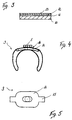
- the clip on the Side facing the reflector is one that projects beyond the thickness or strength of the clip Support surface for the reflector on and on this support surface is the Fastening button provided with a neck-like constriction. This apparently Oversized contact surface helps stabilize the reflector on the Fluorescent lamp at.
- the fastening button with the constriction has also turned out to be good and secure attachment option highlighted.
- the shoulders of the clip extend beyond the contact surface. This is a further stabilization of the reflector to reach.
- an unshielded fluorescent lamp 1 is in one - not shown - arranged bracket, the bracket for example on a Ceiling is mounted.
- a reflector 2 is arranged, which Fluorescent lamp 1 partially surrounds at a distance.
- the fluorescent lamp 1 partially reach around, provided. By this type of attachment, the reflector 2 is on the Fluorescent lamp 1 swiveling.
- the reflector 2 has in its Vertex recesses 4, these recesses 4 preferably elongated holes are, which extend parallel to the axis of the fluorescent lamp 1.
- the clamp 3 has a fastening button 5, the shape of which Recess corresponds, only one track smaller.
- the fastening button 5 is inserted through the recess 4 and the bracket 3 rotated by 90 °. The twist results in a shape or non-positive connection.
- the reflector 2 can have more than two recesses 4, in which case the unused recesses 4 serve for the residual lighting of the ceiling.
- the reflector 2 extends below the lowest point of the fluorescent lamp 1 and points a straight, horizontal part 6 adjoining the curvature. Part 6 can also connect to the curvature via an oblique transition 7. To a To prevent dusting of the fluorescent lamp 1 and the reflector 2 is one translucent plate 8 is provided which is attached to the part 6.
- the reflector 2 is shown, the curvature of which by a A large number of folds 9 which run parallel to the axis of the fluorescent lamp 1 is achieved.
- the steps of the fold 9 are preferably in 10 mm steps.
- the Generation of the curvature by the bend 9 ensures a Quality improvement of the product.
- the reflector 2 can also be designed as a parabolic mirror reflector. It it is also conceivable, the reflector 2 after any curve or after to execute a parabola or the like.
- the beam angle of the reflector 2 is preferably 90 ° to 110 °.
- the recesses 4 are again provided.
- the structure of the reflector 2 is shown.
- the Reflector 2 made of a base material 10, for example an anodized one Aluminum strip, with 10 on this base material Adhesion promoting layer 11, a layer 12 made of high-purity aluminum is provided.
- a reflection-enhancing layer 13 applied from an oxide.
- the layer 13 can also be made of an oxide colored, for example gold or copper colors.
- the reflector 2 on that of the fluorescent lamp 1 facing side has a layer 13, in particular an oxide layer, which is mirrored.
- This layer 13 can also be used with a spray gun be applied.
- This bracket 3 for the attachment of the reflector 2 on the fluorescent lamp 1 is made of one self-extinguishing material, for example made of polycarbonate.
- the clamp 3 On the side facing the reflector 2, the clamp 3 has a thickness or Thickness of the bracket 3 projecting support surface 14. This will make a better one Stabilization of the reflector 2 reached. A further increase in stability results through the shoulders 15 extending beyond the support surface 14 this bearing surface 14 is the fastening button 5 with a neck-like Constriction 16 is provided. In cooperation with the fastening button 5 then results in the positive or non-positive connection of reflector 2 and Clip 3.
Landscapes
- Engineering & Computer Science (AREA)
- General Engineering & Computer Science (AREA)
- Securing Globes, Refractors, Reflectors Or The Like (AREA)
- Vessels And Coating Films For Discharge Lamps (AREA)
- Non-Portable Lighting Devices Or Systems Thereof (AREA)
Abstract
Description
Claims (10)
- Reflektor für eine Leuchtstofflampe, insbesondere für eine freistrahlende Leuchtstofflampe, wobei der Reflektor die Leuchstofflampe im Abstand teilweise umgibt, dadurch gekennzeichnet, daß der Reflektor (2) auf der der Leuchtstofflampe (1) zugewandten Seite eine Schicht (12, 13), insbesondere eine Oxidschicht, aus harteloxiertem Reinstaluminium aufweist und hochglanzverspiegelt ausgeführt ist, daß dieser Reflektor (2) über mindestens zwei, die Leuchtstofflampe (1) teilweise umgreifenden, Klammern (3) auf der Leuchtstofflampe (1) befestigt ist und über die Klammern (3) auf der Leuchtstofflampe (1) schwenkbar ist und daß jede Klammer (3) an dem dem Reflektor (2) zugewandten Scheitel einen Befestigungsknopf (5) aufweist, wobei dieser Befestigungsknopf (5) durch im Scheitel des Reflektors (2) vorgesehene Ausnehmungen (4) hindurchgreift und nach einer etwa 90° Verdrehung eine form- bzw. kraftschlüssige Verbindung ergibt.
- Reflektor nach Anspruch 1, dadurch gekennzeichnet, daß der Reflektor (2) als Parabolspiegelreflektor ausgebildet ist oder daß die Krümmung des Reflektors (2) kontinuierlich nach einer Kurve, beispielsweise nach einer Parabel o.dgl., ausgeführt ist.
- Reflektor nach Anspruch 1 oder 2, dadurch gekennzeichnet, daß im Scheitel des Reflektors (2) mehrere Ausnehmungen (4) vorgesehen sind.
- Reflektor nach mindestens einem der Ansprüche 1 bis 3, dadurch gekennzeichnet, daß die Krümmung des Reflektors (2) durch eine Vielzahl von Kantungen (9), die parallel zur Achse der Leuchtstofflampe (1) verlaufen, erzielbar ist und die Schrille der Kantung (9) im Abstand von vorzugsweise 10 mm erfolgen.
- Reflektor nach mindestens einem der Ansprüche 1 bis 4, dadurch gekennzeichnet, daß der Reflektor aus einem Grundmaterial (10) , beispielsweise einem anodisierten Aluminiumband, besteht, wobei auf diesem Grundmaterial (10) über eine Haftvermittlungsschicht (11) eine Schicht (12) aus Reinstaluminium vorgesehen ist und auf diese Schicht (12) aus Reinstaluminium mindestens eine reflexionsverstärkende Schicht (13) aus einem Oxid aufgetragen ist und die Schicht (13) aus einem Oxid färbig, beispielsweise Gold- oder Kupferfarben, ausgeführt ist.
- Reflektor nach mindestens einem der Ansprüche 1 bis 5, dadurch gekennzeichnet, daß der Reflektor (2) unter den tiefsten Punkt der Leuchtstofflampe (1) reicht und der Ausstrahlwinkel des Reflektors (2) vorzugsweise 90° bis 110° beträgt, wobei der Reflektor (2) einen, gegebenenfalls an die Krümmung anschließenden, geraden, horizontalen, Teil (6) aufweist.
- Reflektor nach mindestens einem der Ansprüche 1 bis 6, dadurch gekennzeichnet, daß der Reflektor (2) unten über eine lichtdurchlässige Platte (8), Scheibe o.dgl. abgeschlossen ist und die Platte (8), Scheibe o.dgl. am horizontalen Teil (6) des Reflektors (2) befestigt ist.
- Reflektor nach mindestens einem der Ansprüche 1 bis 7, dadurch gekennzeichnet, daß die Klammer (3) für die Befestigung des Reflektors (2) auf der Leuchtstofflampe (1) aus einem selbstverlöschenden Material, beispielsweise aus Polycarbonat, hergestellt ist.
- Reflektor nach mindestens einem der Ansprüche 1 bis 8, dadurch gekennzeichnet, daß die Klammer (3) an der dem Reflektor(2) zugewandten Seite eine die Dicke bzw. Stärke der Klammer (3) überragende Auflagefläche (14) für den Reflektor (2) aufweist und auf dieser Auflagefläche (14) der Befestigungsknopf (5) mit einer halsartigen Einschnürung (16) vorgesehen ist.
- Reflektor nach mindestens einem der Ansprüche 1 bis 9, dadurch gekennzeichnet, daß sich die Schultern (15) der Klammer (3) über die Auflagefläche (14) hinaus erstrecken.
Applications Claiming Priority (2)
| Application Number | Priority Date | Filing Date | Title |
|---|---|---|---|
| DE19904525A DE19904525A1 (de) | 1999-02-04 | 1999-02-04 | Reflektor für eine Leuchtstofflampe |
| DE19904525 | 1999-02-04 |
Publications (2)
| Publication Number | Publication Date |
|---|---|
| EP1026441A2 true EP1026441A2 (de) | 2000-08-09 |
| EP1026441A3 EP1026441A3 (de) | 2001-10-17 |
Family
ID=7896428
Family Applications (1)
| Application Number | Title | Priority Date | Filing Date |
|---|---|---|---|
| EP00102452A Withdrawn EP1026441A3 (de) | 1999-02-04 | 2000-02-04 | Reflektor für eine Leuchtstofflampe |
Country Status (2)
| Country | Link |
|---|---|
| EP (1) | EP1026441A3 (de) |
| DE (1) | DE19904525A1 (de) |
Cited By (1)
| Publication number | Priority date | Publication date | Assignee | Title |
|---|---|---|---|---|
| EP1602875A3 (de) * | 2004-06-03 | 2006-09-27 | Roland Kretschmer | Reflektor-System zur Verwendung mit Leuchten |
Family Cites Families (3)
| Publication number | Priority date | Publication date | Assignee | Title |
|---|---|---|---|---|
| DE3937256C2 (de) * | 1989-11-09 | 1995-10-12 | Peter Quellmalz | Reflektor für langgestreckte Lichtquellen |
| DE9100780U1 (de) * | 1991-01-24 | 1991-04-11 | Schiwek, Peter, Dipl.-Ing., 7812 Bad Krozingen | Parabolspiegelreflektor-Nachrüstsatz für freistrahlende Leuchtstofflampen |
| DE29809869U1 (de) * | 1998-06-04 | 1998-08-06 | Wintermayr Energiekonzepte GmbH, 89081 Ulm | Reflektorvorrichtung |
-
1999
- 1999-02-04 DE DE19904525A patent/DE19904525A1/de not_active Withdrawn
-
2000
- 2000-02-04 EP EP00102452A patent/EP1026441A3/de not_active Withdrawn
Non-Patent Citations (1)
| Title |
|---|
| None |
Cited By (1)
| Publication number | Priority date | Publication date | Assignee | Title |
|---|---|---|---|---|
| EP1602875A3 (de) * | 2004-06-03 | 2006-09-27 | Roland Kretschmer | Reflektor-System zur Verwendung mit Leuchten |
Also Published As
| Publication number | Publication date |
|---|---|
| DE19904525A1 (de) | 2000-08-10 |
| EP1026441A3 (de) | 2001-10-17 |
Similar Documents
| Publication | Publication Date | Title |
|---|---|---|
| EP0898686B2 (de) | Leuchte mit einem basiskörper als träger für wenigstens eine lampe | |
| EP0665936B1 (de) | Leuchte mit langgestrecktem leuchtmittel und reflektoren | |
| DE69200494T2 (de) | Leuchte zum Schaffen eines Hauptbündels und eines Teilbündels. | |
| WO2001059364A1 (de) | Leuchte | |
| DE10360943A1 (de) | Beleuchtungseinrichtung | |
| EP0122972A1 (de) | Blendungsfreie Leuchte für eine stabförmige Lichtquelle | |
| EP0716262B1 (de) | Leuchte für langgestreckte Leuchtmittel | |
| EP0235652B1 (de) | Blendungsfreie Leuchte mit streifenförmigen Abblendreflektor | |
| EP3270047A2 (de) | Flachleuchte | |
| DE19537685C1 (de) | Breitstrahlende Indirektleuchte | |
| EP1026441A2 (de) | Reflektor für eine Leuchtstofflampe | |
| WO2006133861A1 (de) | Innenraumleuchte | |
| EP0222115B1 (de) | Deckenleuchte | |
| EP0638764B2 (de) | Vorwiegend direkt strahlende Innenleuchte | |
| DE3687685T2 (de) | Leuchten. | |
| DE3902494C2 (de) | Indirekte Spiegelleuchte | |
| DE9302433U1 (de) | Anordnung zur Ausleuchtung von Hintergrundflächen | |
| EP2813753B1 (de) | Leuchte | |
| EP1045196A2 (de) | Beleuchtungseinrichtung mit einer Tragbasis | |
| DE8316217U1 (de) | Innenraumleuchte fuer entladungslampen | |
| DE202007013177U1 (de) | Leuchte | |
| DE29613948U1 (de) | Leuchte mit mindestens einer Lampe, einem Reflektor und einem Rasterreflektor | |
| EP3364099B1 (de) | Modulare leuchte mit direkt- und indirektanteil | |
| DE29801998U1 (de) | Spiegel | |
| DE19648310A1 (de) | Leuchte mit einer Lampe und mindestens einem Lichtdämpfungsteil |
Legal Events
| Date | Code | Title | Description |
|---|---|---|---|
| PUAI | Public reference made under article 153(3) epc to a published international application that has entered the european phase |
Free format text: ORIGINAL CODE: 0009012 |
|
| AK | Designated contracting states |
Kind code of ref document: A2 Designated state(s): AT BE CH CY DE DK ES FI FR GB GR IE IT LI LU MC NL PT SE |
|
| AX | Request for extension of the european patent |
Free format text: AL;LT;LV;MK;RO;SI |
|
| PUAL | Search report despatched |
Free format text: ORIGINAL CODE: 0009013 |
|
| AK | Designated contracting states |
Kind code of ref document: A3 Designated state(s): AT BE CH CY DE DK ES FI FR GB GR IE IT LI LU MC NL PT SE |
|
| AX | Request for extension of the european patent |
Free format text: AL;LT;LV;MK;RO;SI |
|
| AKX | Designation fees paid | ||
| REG | Reference to a national code |
Ref country code: DE Ref legal event code: 8566 |
|
| STAA | Information on the status of an ep patent application or granted ep patent |
Free format text: STATUS: THE APPLICATION IS DEEMED TO BE WITHDRAWN |
|
| 18D | Application deemed to be withdrawn |
Effective date: 20020418 |