EP1024493B1 - Digital signal transmission, computer program product, and recording medium - Google Patents
Digital signal transmission, computer program product, and recording medium Download PDFInfo
- Publication number
- EP1024493B1 EP1024493B1 EP00300576.6A EP00300576A EP1024493B1 EP 1024493 B1 EP1024493 B1 EP 1024493B1 EP 00300576 A EP00300576 A EP 00300576A EP 1024493 B1 EP1024493 B1 EP 1024493B1
- Authority
- EP
- European Patent Office
- Prior art keywords
- mode
- electronic equipment
- transmission
- digital signal
- command
- Prior art date
- Legal status (The legal status is an assumption and is not a legal conclusion. Google has not performed a legal analysis and makes no representation as to the accuracy of the status listed.)
- Expired - Lifetime
Links
Images


Classifications
-
- H—ELECTRICITY
- H04—ELECTRIC COMMUNICATION TECHNIQUE
- H04L—TRANSMISSION OF DIGITAL INFORMATION, e.g. TELEGRAPHIC COMMUNICATION
- H04L12/00—Data switching networks
- H04L12/28—Data switching networks characterised by path configuration, e.g. LAN [Local Area Networks] or WAN [Wide Area Networks]
- H04L12/40—Bus networks
- H04L12/40052—High-speed IEEE 1394 serial bus
- H04L12/40117—Interconnection of audio or video/imaging devices
-
- G—PHYSICS
- G11—INFORMATION STORAGE
- G11B—INFORMATION STORAGE BASED ON RELATIVE MOVEMENT BETWEEN RECORD CARRIER AND TRANSDUCER
- G11B20/00—Signal processing not specific to the method of recording or reproducing; Circuits therefor
- G11B20/10—Digital recording or reproducing
-
- G—PHYSICS
- G11—INFORMATION STORAGE
- G11B—INFORMATION STORAGE BASED ON RELATIVE MOVEMENT BETWEEN RECORD CARRIER AND TRANSDUCER
- G11B20/00—Signal processing not specific to the method of recording or reproducing; Circuits therefor
- G11B20/10—Digital recording or reproducing
- G11B20/10527—Audio or video recording; Data buffering arrangements
-
- G—PHYSICS
- G11—INFORMATION STORAGE
- G11B—INFORMATION STORAGE BASED ON RELATIVE MOVEMENT BETWEEN RECORD CARRIER AND TRANSDUCER
- G11B27/00—Editing; Indexing; Addressing; Timing or synchronising; Monitoring; Measuring tape travel
- G11B27/02—Editing, e.g. varying the order of information signals recorded on, or reproduced from, record carriers
- G11B27/031—Electronic editing of digitised analogue information signals, e.g. audio or video signals
- G11B27/034—Electronic editing of digitised analogue information signals, e.g. audio or video signals on discs
-
- G—PHYSICS
- G11—INFORMATION STORAGE
- G11B—INFORMATION STORAGE BASED ON RELATIVE MOVEMENT BETWEEN RECORD CARRIER AND TRANSDUCER
- G11B27/00—Editing; Indexing; Addressing; Timing or synchronising; Monitoring; Measuring tape travel
- G11B27/10—Indexing; Addressing; Timing or synchronising; Measuring tape travel
- G11B27/102—Programmed access in sequence to addressed parts of tracks of operating record carriers
- G11B27/105—Programmed access in sequence to addressed parts of tracks of operating record carriers of operating discs
-
- G—PHYSICS
- G11—INFORMATION STORAGE
- G11B—INFORMATION STORAGE BASED ON RELATIVE MOVEMENT BETWEEN RECORD CARRIER AND TRANSDUCER
- G11B27/00—Editing; Indexing; Addressing; Timing or synchronising; Monitoring; Measuring tape travel
- G11B27/10—Indexing; Addressing; Timing or synchronising; Measuring tape travel
- G11B27/19—Indexing; Addressing; Timing or synchronising; Measuring tape travel by using information detectable on the record carrier
- G11B27/28—Indexing; Addressing; Timing or synchronising; Measuring tape travel by using information detectable on the record carrier by using information signals recorded by the same method as the main recording
- G11B27/30—Indexing; Addressing; Timing or synchronising; Measuring tape travel by using information detectable on the record carrier by using information signals recorded by the same method as the main recording on the same track as the main recording
- G11B27/3027—Indexing; Addressing; Timing or synchronising; Measuring tape travel by using information detectable on the record carrier by using information signals recorded by the same method as the main recording on the same track as the main recording used signal is digitally coded
-
- H—ELECTRICITY
- H04—ELECTRIC COMMUNICATION TECHNIQUE
- H04L—TRANSMISSION OF DIGITAL INFORMATION, e.g. TELEGRAPHIC COMMUNICATION
- H04L12/00—Data switching networks
- H04L12/28—Data switching networks characterised by path configuration, e.g. LAN [Local Area Networks] or WAN [Wide Area Networks]
- H04L12/40—Bus networks
- H04L12/40052—High-speed IEEE 1394 serial bus
- H04L12/40058—Isochronous transmission
-
- H—ELECTRICITY
- H04—ELECTRIC COMMUNICATION TECHNIQUE
- H04L—TRANSMISSION OF DIGITAL INFORMATION, e.g. TELEGRAPHIC COMMUNICATION
- H04L12/00—Data switching networks
- H04L12/28—Data switching networks characterised by path configuration, e.g. LAN [Local Area Networks] or WAN [Wide Area Networks]
- H04L12/40—Bus networks
- H04L12/40052—High-speed IEEE 1394 serial bus
- H04L12/40065—Bandwidth and channel allocation
-
- G—PHYSICS
- G11—INFORMATION STORAGE
- G11B—INFORMATION STORAGE BASED ON RELATIVE MOVEMENT BETWEEN RECORD CARRIER AND TRANSDUCER
- G11B2220/00—Record carriers by type
- G11B2220/20—Disc-shaped record carriers
- G11B2220/25—Disc-shaped record carriers characterised in that the disc is based on a specific recording technology
- G11B2220/2525—Magneto-optical [MO] discs
- G11B2220/2529—Mini-discs
-
- G—PHYSICS
- G11—INFORMATION STORAGE
- G11B—INFORMATION STORAGE BASED ON RELATIVE MOVEMENT BETWEEN RECORD CARRIER AND TRANSDUCER
- G11B2220/00—Record carriers by type
- G11B2220/20—Disc-shaped record carriers
- G11B2220/25—Disc-shaped record carriers characterised in that the disc is based on a specific recording technology
- G11B2220/2537—Optical discs
- G11B2220/2545—CDs
-
- G—PHYSICS
- G11—INFORMATION STORAGE
- G11B—INFORMATION STORAGE BASED ON RELATIVE MOVEMENT BETWEEN RECORD CARRIER AND TRANSDUCER
- G11B31/00—Arrangements for the associated working of recording or reproducing apparatus with related apparatus
Definitions
- the present invention relates to a digital signal transmission method, a digital signal transmission system, transmitting apparatus, a recording medium for recording a program applied to this transmission system and a computer program product.
- An illustrative embodiment of the invention is preferably applicable to a case where audio data is transmitted, for example, according to IEEE (The Institute of Electronics Engineers, Inc.) 1394.
- An audio equipment as related art has been proposed, in which an audio signal is transmitted in the digital form so that the deterioration of sound quality can effectively be avoided.
- the compact disk player when an audio signal reproduced by the compact disk player is recorded by means of a minidisk device in this sort of audio equipment, the compact disk player modulates the reproduced digital audio signal according to a clock signal of these digital audio signal for outputting.
- the minidisk device on the receiving side employs the PLL circuit to reproduce a clock signal from the transmitted digital signal and then reproduces the transmitted digital signal with reference to the clock signal.
- this sort of audio equipment processes the digital audio signal transmitted in synchronism with a clock signal on the transmitting side, for example, to perform processing of recording and so on.
- the receiving side will operate synchronously with the clock signal of the transmitted digital audio signal.
- a bus line of IEEE 1394 system is employed to connect a plurality of audio equipments and, for example, the digital audio signal reproduced from the disk, etc. of a single audio reproducing equipment is sent out to the bus line. That digital audio signal is received and recorded by a recording equipment connected to the bus line.
- control data regarding the reproducing operation, etc. is transmitted over the bus line to synchronize the two equipments.
- the bus line of IEEE 1394 system is able to connect two or more equipments with one another.
- the reproducing unit should receive, e.g. control data from another equipment during the recording operation to stop the reproduction, the recording would be interrupted to result in failure.
- EP 0,841,776 describes a system for carrying out communication between a plurality of apparatus connected using an IEEE 1394 serial bus.
- Command register addresses are fixed from "FFFF F000 0B00h” to "FFFF F000 0D00h” and response register addresses are fixed from "FFFF F000 0D00h” to "FFFF F000 0DF0H”. These addresses are then common to all of the apparatus connected to the bus. Then, while an arbitrary apparatus on the bus is sending a command to all of the remaining apparatus, the address of the command register is included in the command and this command is transmitted as a broadcast communication. This command is then stored at a command register having a common address within the apparatus that received the command. Thus, time setting and state setting etc. of each apparatus can be achieved.
- EP 0,932,160 describes a transmitting system consisting of a control apparatus and a target apparatus connected mutually via an IEEE1394 bus.
- Unitary data having an isochronous gap for transmission of audio main data and an asynchronous gap for transfer of command data are transmitted between the control apparatus and the target apparatus via the bus.
- the control apparatus comprises a means for sending an identifier to identify the target apparatus by the use of the asynchronous gap, and also a command to request transfer of a signal level from the target apparatus.
- the target apparatus comprises a means for receiving the identifier from the sending means of the control apparatus via the IEEE1394 bus and also the command to request transfer of the signal level of the target apparatus; and a means for sending an audio signal level in response to the signal-level transfer request command received by the receiving means.
- an output level can be set in and read out from the target apparatus by the control apparatus.
- Illustrative embodiments of the invention described herein seek to provide that digital signal transmission between specific equipments is carried out securely and satisfactorily.
- An embodiment of the present invention is arranged so that, when a digital signal destination is caused to receive a predetermined digital signal sent out of a digital signal sender, a flag is added to the digital signal sent out of the digital signal sender, which indicates that a transmission rate is being adjusted based on a command from the digital signal destination.
- the destination is able to check the transmitted flag, so that the processing to eliminate the jitters by the fine adjustment of the transmission rate and the like will be allowed.
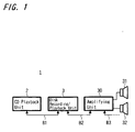
- FIG. 1 is a schematic block diagram showing an illustrative audio system according to an illustrative mode for carrying out the present invention.
- the audio system 1 of this example transmits a digital audio signal reproduced by a compact disk playback unit 2 to a disk recording/playback unit 3 using a magneto-optical disk (or optical disk) called a minidisk, etc. and records that signal by this disk recording/playback unit 3. Otherwise, the digital audio signal reproduced by the compact disk playback unit 2 is transmitted to an amplifying unit 30 for causing right and left speaker units 31, 32 connected to this amplifying unit 30 to output the audio signal as a sound.
- a magneto-optical disk or optical disk
- bus lines B1, B2 defined by the IEEE 1394 interface system connect the compact disk playback unit 2, the disk recording/playback unit 3 and the amplifying unit 30 with one another. Additionally, in the case of IEEE 1934 interface system, the connection may be made in any order. Figure 1 shows only one example of them. Also, it may be possible to connect them to another audio equipment and the like not shown by another bus line B3.
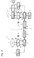
- FIG. 2 is a block diagram showing structures of the compact disk playback unit 2 and the disk recording/playback unit 3 of the audio system according to the present embodiment.
- a digital signal processor ( DSP ) 5 drives to rotate an optical disk 7 being a digital audio disk under the control of a host computer 6 by means of a rotation drive mechanism not shown and reproduces the digital audio signal DA recorded on this optical disk 7 for outputting.
- the digital signal processor 5 produces a clock signal WCK by a built-in quartz oscillator circuit 8, reproduces the digital audio signal DA in synchronism with this clock signal WCK and also outputs the reproduced digital audio signal DA to an audio link block 9.
- the digital signal processor 5 plays back the compact disk 7 at a playback speed instructed by the host computer 6 to output the digital audio signal DA. Additionally, in the case of this example, it is arranged that the playback speed can be set for, other than one-fold speed (i.e. normal playback speed ), two-fold speed, four fold speed, eight-fold speed and sixteen-fold speed.
- the reproduction rate can further be adjusted accurately by plus or minus several percent ( e.g. ⁇ 1 percent or so ).
- the audio link block 9 makes the digital audio signal DA into the form of packets under the control of host computer 6 and controls an input-output circuit 10 to send out these packets to the disk recording/playback unit 3. Also, the audio link block 9 acquires the packets input through the input-output circuit 10 and sends out the contents of these packets to the host computer 6 as need arises.
- the input-output circuit 10 parallel-serial converts output data of the audio link block 9 and after adding a predetermined data, biphase mark modulates for outputting to the bus line B1. In this way, the input-output circuit 10 superposes the clock signal WCK required for reproducing the packets on those packets input from the audio link block 9 for sending out to the bus line B1. Also, the input-output circuit 10 watches the packets transmitted over the bus line B1 to acquire the packets specifying the compact disk playback unit 2. The input-output circuit 10 then decodes these acquired packets and processes to serial-parallel convert for outputting to the audio link block 9.
- the compact disk playback unit 2 is herein connected to the disk recording/playback unit 3 by the bus line B1 defined by the IEEE 1394 interface system.
- the audio link block 9 and the input-output circuit 10 make the digital audio signal DA into the packets according to the format defined by the IEEE 1394 and also notify data transmitted in the form of packets to the host computer 6.
- the digital audio signal DA is transmitted as the isochronous transfer packet defined by the IEEE 1394 interface ensuring its real-time nature, as where the other data such as various kinds of control commands are transmitted as asynchronous transfer packet in asynchronous manner as occasion demands.
- the asynchronous transfer packet is a packet used for one-to-one correspondence, in which addresses of the data sender and its destination are indicated.
- Figure 3 shows a cyclic structure in data transmission by equipments connected in accordance with the IEEE 1394.
- data are divided into packets and transmitted by timesharing in a cycle of 125 MS length. This cycle is created by a cycle start signal supplied from an electronic equipment having a cycle-master function.
- the isochronous packet ensures necessary band (This is a time unit but called a band.) for transmission from the start of every cycle.
- the isochronous transmission guarantees a data transmission within a fixed time. However, if transmission error occurs, data will be lost because of no protection mechanism.
- the electronic equipment which ensures a bus as a result of arbitration sends out the asynchronous packet.
- the asynchronous transmission ensures a secure transmission by using acknowledge and retry, but the transmission timing will be uncertain.
- the electronic equipments In order that predetermined electronic equipments may perform the isochronous transmission, the electronic equipments must correspond to an isochronous function. Moreover, at least one of the electronic equipments must have the cycle-master function. Furthermore, at least one of the electronic equipments connected to the IEEE 1394 serial bus must have an isochronous-resource-manager function.
- the IEEE 1394 is based upon CSR(Control & Status Register) architecture having an address space of sixty-four bits defined by ISO/IEC 13213.
- Figure 4 illustrates a structure of the address space in accordance with the CSR architecture.
- High order sixteen bits form a node ID indicating each electronic equipment on the IEEE 13 94. Remaining forty-eight bits are used for specifying the address space given each electronic equipment.
- These high order sixteen bits are further divided into ten bits of bus ID and six bits of physical ID (node ID in a narrow sense). They can specify a thousand and twenty-three buses and sixty-three electronic equipments because a value in which all bits become one is used for a special purpose.
- a space defined by high order twenty bits of the address space of two hundreds and fifty-six terabytes defined by low order forty-eight bits are divided into an Initial Register Space used for a register of two thousand and forty-eight bytes unique to CSR, a register unique to the IEEE 1394 and the like, Private Space and initial Memory Space.
- a space defined by low order twenty-eight bits is, if a space defined by its high order twenty bits is initial Register Space, used as Configuration Read Only Memory, an initial Unit Space used for special purpose unique to an electronic equipment, Plug Control Register (PCRs) and the like.
- each electronic equipment has the CSR shown in Figure 4 , as concerns a bandwidth available register, only those contained by the isochronous resource manager are valid. In other words, the bandwidth available register is substantially included in only the isochronous resource manager.
- Each bit of channels available register between offset 224h and 228h corresponds to channel no. zero to 63, respectively. If the bit is equal to zero, it is indicated that channel has already been allocated. Only the channels available register of an electronic equipment operating as the isochronous resource manager is valid.
- an electronic equipment has PCR (Plug Control Register) defined by IEC 61883 in addresses 900 h to 9FFh within initial Unit Space shown in Figure 4 .
- PCR Plug Control Register
- Figure 5 illustrates the structure of PCR.
- the PCR has oPCR (output Plug Control Register) representing an output plug and iPCR (input Plug Control Register) representing an input plug.
- the PCR has oMPR (output Master Plug Register) and iMPR (input Master Plug Register) indicative of information on output plug or input plug unique to each equipment.
- Each equipment does not have a plurality of oMPR and iMPR, but is able to have a plurality of oPCR and iPCR corresponding to each individual plug.
- the PCR shown in Figure 5 has thirty-one oPCR and iPCR, respectively. A flow of isochronous data is controlled by operating the register corresponding to these plugs.
- Figure 6 (A) to (D) show structures of oMPR, oPCR, iMPR and iPCR:
- Figure 6 (A) shows the structure of oMPR;
- Figure 6(B) shows the structure of oPCR;
- Figure 6(C) shows the structure of iMPR;
- Figure 6(D) shows the structure of iPCR, respectively.
- An area of data rate capability of two bits on the side of MSB of oMPR and iMPR stores a code indicating the maximum transmission speed of isochronous data which can be transmitted or received by that equipment.
- An area of broadcast channel base of oMPR prescribes the channel number used for broadcast output.
- An area of number of output plugs of five bits on the side of LSB of oMPR stores a value indicating the number of output plugs owned by the relevant equipment, namely, the number of oPCR.
- An area of number of input plugs of five bits on the side of LSB of iMPR stores a value indicating the number of input plugs owned by the relevant equipment, namely, the number of iPCR.
- Areas of non-persistent extension field and persistent extension field are those defined for future extension.
- Each area of on-line of MSB in oPCR and iPCR shows a state of use of the plug. In other words, its value of one shows that the plug is on-line and its value of zero shows that the plug is offline.
- a value of each broadcast connection counter of oPCR and iPCR indicated whether the broadcast connection is present (1) or not (0).
- a value of each point-to-point connection counter being six bits wide of oPCR and iPCR indicates the number of point-to-point connection owned by the relevant plug.
- a value of each channel number six bits wide of oPCR and iPCR indicates the isochronous channel number to which the relevant plug is connected.
- a value of data rate two bits wide of oPCR indicates an actual transmission speed of isochronous data packet output by the relevant plug.
- a code stored in an area of overhead ID four bits wide of oPCR represents a bandwidth of overhead of isochronous communication.
- a value of payload ten bits wide of oPCR represents the maximum value of data contained in isochronous packet, in which the relevant plug can handle.
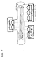
- Figure 7 shows a relation between the plug, the plug control register and the isochronous channel.
- AV-devices 50 to 52 are connected to each other by means of the IEEE 1394 serial bus.
- the isochronous data whose channel is specified by oPCR [1], of oPCR [0] to oPCR [2] whose transmission speed and number of oPCRs by oMPR of AV-device 52 are defined, is sent out to channel no. 1 of the IEEE 1394 serial bus.
- AV-device 50 reads and stores the isochronous data sent out to the channel no. 1 of the IEEE 1394 serial bus.
- AV-device 51 sends out isochronous data to channel no. 2 specified by oPCR [0], and AV-device 50 reads the isochronous data from the channel no. 2 specified by iPCR [1] and stores it.
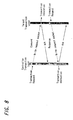
- Figure 8 illustrates the control command and the response transmitted asynchronously.
- the controlling side is indicated as controller and the controlled side is indicated as target.
- Transmission or its response of the control command is performed between electronic equipments using Write Transaction of asynchronous transmission in IEEE 1394.
- the target which receives data returns acknowledgement (ACK) to the controller for confirming the reception.
- ACK acknowledgement
- FIG 9 illustrates in more detail the relation between the control command and the response shown in Figure 8 .
- An electronic equipment A is connected with an electronic equipment B through the IEEE 1394 bus.
- the electronic equipment A is the controller and the electronic equipment B is the target.
- the electronic equipment A and the electronic equipment B both have a command register and a response register each of which has 512 bytes, respectively.
- the controller communicates the command by writing a command message into the command register 123 of the target.
- the target communicates the response by writing a response message into the response register 122 of the controller.
- the control information is thus exchanged by the two messages made a pair.
- Figure 10 is a diagram showing a part of the isochronous transfer packet used for the aforesaid isochronous transfer.
- a header is assigned to this packet, which occupies 32 x 2 bits from front and includes synchronizing pattern sy, packet code tcode, channel, tag, data length and error correction code CRC.
- To the subsequent 32 bits are assigned count value of successive packets DBC when data of a fixed size are divided to be assigned to each packet, Reserve RSV, Marker SPH indicating whether there is a source packet header or not, Divisional number of source packet FN, Data block size DBS, Identification code of its own SID and so on.
- Recording area SYT such as a time stamp, Sampling frequency FDF of transmitted data, Transmission format FMT and so on.
- transmitted data made of source data with 32 bits as a unit, and their error correction code CRC is added to its end.
- one bit at a specific position in the area of Sampling frequency FDF made of eight bits is used for adding a flag FC indicating that the transmission rate of audio signal is being controlled. If this flag FC is "1" signal, it indicates that a mode in which the transmission rate is controlled is entered. If the flag FC is "0" signal, it indicates that a mode in which the transmission rate is not controlled is entered. Further, in the following description, a mode in which the transmission rate is controlled will be referred to a flow control mode.
- the audio link block 9 adds the digital audio signal DA to this isochronous transfer packet by a fixed unit and sends it out through the input-output circuit 10.
- Figure 11 is a diagram showing the asynchronous transfer packet being the packet for asynchronous communication by one-to-one of the aforesaid control command and the like.
- the input-output circuit 10 sets the address, etc. indicating its own node and bus number or the like on the packet for sending it out. Specifically, to 32 bits from the front of the packet are assigned Priority level of this packet (priority ), Code of this packet ( Code t ), Retry code of this packet (rt), Label assigned to this packet ( Label t ), Transmission speed (spd) and Identification data indicating the relation with successive packets ( imm).
- data specifying an address of destination node ( destination Offset High, destination Offset Low ) and data indicating the destination node and bus ( destination ID) are assigned.
- Data length of the transmission data ( data Length), etc. are further assigned and then the transmission data is assigned with 32 bits as a unit.
- the audio link block 9 receives the packet for one-to-one communication received by the input-output circuit 10 and notifies the data assigned to this packet to the host computer 6. In this way, various kinds of control commands transmitted from the disk recording/playback unit 3 to the compact disk playback unit 2 are notified to the host computer 6.
- the host computer 6 is comprised of a computer which controls the overall operation of compact disk playback unit 2, and controls the operation of digital signal processor 5 in response to an operation of operating elements arranged on an operating panel of the compact disk playback unit 2 to play back the optical disk 7.
- the host computer 6 receives the control command sent out of the disk recording/playback unit 3 through the audio link block 9 and controls the playback operation of compact disk 7 in accordance with the control command.
- the host computer 6 receives the control command to finely adjust a reproduction rate from the disk recording/playback unit 3, it instructs the digital signal processor 5 so as to turn the playback conditions of compact disk 7 into the corresponding conditions.
- the host computer 6 receives from the disk recording/playback unit 3 the control command to switch the playback speed, it instructs the digital signal processor 5 to switch the playback speed in accordance with this command.
- the compact disk playback unit 2 sends out the digital audio signal DA in the form of a variable amount of data per unit time under the control of disk recording/playback unit 3.
- An input-output circuit 11 in the disk recording/playback unit 3 watches packets transmitted over the bus lines B1, B2, in the same way as the input-output circuit 10 in the compact disk playback unit 2 and acquires the packet necessary for the disk recording/playback unit 3.
- the input-output circuit 11 further reproduces the acquired packet and notifies it to an audio link block 12.
- the input-output circuit 11 detects data transmitted from the bus lines B1, B2 Synchronously with a predetermined clock signal to reproduce each data within the transmitted packet.
- the processing to reproduce is made in synchronism with the transmitted audio data with reference to the time stamp arranged in the recording area SYT.
- the reproduction is made without reference to the time stamp arranged in the recording area SYT.
- the detection is made synchronously with the clock signal produced by a clock generator circuit within the disk recording/playback unit 3 to reproduce the transmitted packet.
- the reproduction using the time stamp may be carried out.
- An audio link block 12 acquires a packet from the input-output circuit 11 and stores the digital audio signal DA assigned to this packet in the recording area of digital audio signal DA arranged in a memory 13. Also, the audio link block 12 outputs the digital audio signal DA retained in the memory 13 to a digital signal processor 14 or a digital-to-analog converter (D/A) 16 and stops the readout of digital audio signal DA from the memory 13 under the control of a host computer 15.
- D/A digital-to-analog converter
- the audio link block 12 records the digital audio signal DA in the memory 13 with reference to the clock signal WCK superposed on input data, synchronized with the clock signal WCK of the compact disk playback unit 2, and then reads it out based on a clock signal RCK output from the digital signal processor 14 for outputting.
- a recording block 18 is composed of a driving mechanism for driving to rotate the disk and a recording/reproducing system such as the optical pickup, and forms a mark sequentially on the magneto-optical disk depending on recording signals output from the digital signal processor 14.
- the digital signal processor 14 controls the operation of recording block 18 and also produces the recording signal depending on the digital audio signal DA output from the audio link block 12 for outputting.
- the digital audio signal DA is recorded on the disk by means of the digital signal processor 14 and the recording block 18.
- the digital signal processor 14 produces the clock signal RCK by a built-in quartz oscillator 19, which is asychronous with the clock signal WCK of the compact disk playback unit 2 and besides of high accuracy, and processes the digital audio signal DA output from the audio link block 12 with reference to the clock signal RCK. It also outputs this clock signal RCK to the recording block 18, the digital-to-analog converter 16 and the audio link block 12.
- the digital-to-analog converter 16 is what is called a one bit digital-to-analog converter which converts the digital audio signal DA to an analog signal according to PWM modulation method. It can also produce an audio signal converted to the analog signal in order to drive a speaker 4 connected to the disk recording/payback unit.
- the host computer 15 is comprised of a computer which controls the overall operation of disk recording/playback unit 3, and controls the operation of digital signal processor 14, etc. in response to an operation of operating elements arranged on an operating panel of the disk recording/playback unit 3, thereby causing the digital audio signal DA to be recorded on the disk or to be output from the speaker 4.
- the host computer 15 when processing the digital audio signal DA transmitted from the compact disk playback unit 2, the host computer 15 produces the control command to the compact disk playback unit 2 depending on an amount of data of the digital audio signal DA retained in the memory 13. It performs the flow control processing using this command, in which an amount of data of the digital audio signal DA per unit time sent out from the compact disk playback unit 2 is variably controlled in dependence on the amount of data of digital audio signal DA retained in the memory 13.
- the flow control processing will be described below in detail.
- the compact disk playback unit 2 is hereinafter referred to merely as a playback unit 2 and the disk recording/playback unit 3 is referred to merely as a recording unit 3.
- Figure 12 shows a control sequence in this case. An example is herein shown, in which the side of recording unit 3 being a receiving side of the audio signal transmitted over the bus line controls the transmission.
- a transmission setting command for setting transmission conditions FLOW CONFIGURATION
- a transmission attributes command for examining transmission attributes FLOW ATTRIBUTES
- the transmission setting command includes control data and status data.
- the transmission attributes command includes only status data.
- the recording unit 3 transmits first the transmission attributes command S11 for examining the flow control mode to the playback unit 2.
- Figure 14 shows an example of data structure of the transmission attributes command in this case, in which are arranged a code of FLOW ATTRIBUTES indicating that it is the transmission attributes command, a code of FLOW Mode indicating that it examines the transmission mode and so on.
- Figure 15 shows an example of data structure of the transmission attributes command of response in this case, in which data of FLOW Mode attributes [0] to [7] indicate whether or not the respective modes previously prepared for a standard are supported by the playback unit 2.
- Figure 16 shows the details of modes prepared in the case of this example.
- a mode indicated by the first bit is a locked normal mode at one-fold speed of playback speed
- a mode indicated by the second bit is an unlocked flow control mode at one-fold speed of playback speed
- a mode indicated by the third bit is a locked flow control mode at one-fold speed of playback speed
- a mode indicated by the fourth bit is a locked flow control mode at four-fold speed of playback speed
- a mode indicated by the fifth bit is a locked flow control mode at eight-fold speed of playback speed
- a mode indicated by the sixth bit is a locked flow control mode at sixteen-fold speed of playback speed.
- "1" signal in any of the respective bit positions indicates the supported mode ( i.e.
- the locked mode is such that, when the mode is set, that mode is locked. Unlocking of that mode is made possible only by an equipment specifying that mode. The unlocked mode is such that this sort of locking is not carried out. Thus, changing this mode is possible by any equipment.
- a limitation is imposed on changing the mode. Details of the limitation will be described below.
- the side of recording unit 3 can estimate modes which can be sent out of the playback unit 2.
- the recording unit 3 selects the mode of transmission to be performed among the estimated modes. This selection may be made, for example, by user's key operation at the recording unit 3 or by automatically setting a mode which enables the fastest and satisfactory recording.
- Data of the selected mode is transmitted as the transmission setting command S13 from the recording unit 3 to the playback unit 2.
- Figure 17 shows an example of this transmission setting command S13. This includes a code of transmission setting command ( FLOW CONFIGURATION) and a code of source ( Source ) being data on the selected mode. Also, data on a flow mode are added. Examples of transmission modes indicated by the source code are shown in Figure 18 .
- a code “0 0” indicates an unlocked mode at one-fold speed of playback speed
- a code “0 1” indicates a locked mode at one-fold speed of playback speed
- a code “0 2” indicates an unlocked flow control mode at one-fold speed of playback speed
- a code “0 3” indicates a locked flow control mode at two-fold speed of playback speed
- a code “0 4" indicates a locked flow control mode at four-fold speed of playback speed
- a code “0 5" indicates a locked flow control mode at eight-fold speed of playback speed
- a code “0 6” indicates a locked flow control mode at sixteen-fold speed of playback speed.
- a code "AA” indicates data specifying a standard rate
- a code “BB” indicates data specifying a rate somewhat higher than the standard rate
- a code “CC” indicates data specifying a rate somewhat lower than the standard rate.
- the standard rate is specified basically.
- the playback unit 2 When the playback unit 2 receives the transmission setting command S13, it transmits to the recording unit 3 a response command S14 to that command. The playback unit 2 then reproduces the audio signal from the optical disk 7 at a playback speed corresponding to the mode specified by that command and transmits the reproduced audio signal on the isochronous transfer packets to the recording unit 3.
- the recording unit 3 transmits a transmission setting command S15 for rate control.
- the playback unit 2 receives this transmission setting command S15, it transmits to the recording unit 3 a response command S16 to that command and also adjusts the reproduction rate finely to a state specified by that command.
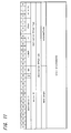
- Figure 19 shows an example of the transmission setting command for the rate control, to which the codes for specifying rates shown in Figure 20 are added for transmission.
- Figure 21 is a flow chart showing the sequence in which the rate control takes place.
- the host computer 15 of the recording unit 3 moves from a step SP1 to a step SP2 to produce a control command directing the playback unit 2 through the audio link block 12 and the input-output circuit 11 to start the reproduction and start sending-out of the digital audio signal DA.
- the host computer 6 of the playback unit 2 which has received this control command starts playing-back of the disk 7 and sends out, at the following step SP4, the reproduced digital audio signal DA from the playback unit 2.
- the host computer 15 sets the operation of audio link block 12, at the next step SP5, to store in the memory 13 the digital audio signal DA sent out of the playback unit 2 and then moves to a step SP6.
- the host computer 15 measures here whether or not a predetermined amount or more of the digital audio signal DA has been stored in the memory 13 and if a negative result is given, it will repeat the step SP6.
- the host computer 15 decides at this step SP6 that a predetermined or more value of the data amount has been stored and moves to a step SP7.
- the host computer 15 directs the audio link block 12 to start the readout of digital audio signal DA from the memory 13. In this way, the host computer 15 controls the overall operation so as to start the processing to read out the digital audio signal DA reproduced and transmitted by the playback unit 2 in accordance with the more accurate clock signal RCK asynchronous with the clock signal WCK of the playback unit 2.
- the host computer 15 moves to a step SP8 and measures whether or not the memory 13 is just before an overflow.
- the data amount of digital audio signal DA read out of the memory 13 is less than that of digital audio signal DA sent out of the compact disk playback unit 2 and stored in the memory 13 accordingly.
- the data amount of digital audio signal DA stored by degrees in the memory 13 will increase until the memory 13 overflows, which makes it difficult to process the digital audio signal DA continuously.
- the host computer 15 decides at this step SP8 that it is in the over conditions and moves to a step SP9 for transmitting the rate control command to make the rate slower to the side of playback unit 2.
- the host computer 15 moves subsequently to a step SP10 and measures whether or not the data amount of digital audio signal DA stored in the memory 13 becomes less than the data amount whose readout was started at the step SP7 and if a negative result is given, it will repeat the step SP10.
- the host computer 15 waits until the data amount stored in the memory 13 becomes under the given value and when it becomes under the given value, a positive result will be given at the step SP10.
- the computer moves to a step SP11 for transmitting to the side of playback unit 2 the rate control command to return the rate to the standard.
- the host computer 15 moves to a step SP12 and measures here whether or not the data amount stored in the memory 13 is just before the under conditions.
- step SP13 transmits to the side of playback unit 2 the rate control command to make the rate faster. This prevents the digital audio signal DA from being interrupted.
- the host computer 15 will obtain the negative result at the step SP12 and return to the step SP8.
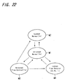
- Figure 22 shows the limits in which the modes can vary.
- the unlocked normal mode of one-fold speed M1 being the normal mode can change into any mode.
- the locked normal mode of one-fold speed M2 can only return to the unlocked normal mode of one-fold speed M1.
- the unlocked flow control mode of one-fold speed M3 can change into the unlocked normal mode of one-fold speed M1, the locked normal mode of one-fold speed M2 and the locked flow control mode of two-fold or more speed M4.
- the locked flow control mode of two-fold or more speed M4 can only change into the unlocked normal mode M1.
- the compact disk playback unit 2 sends out the digital audio signal in the form of variable amount of data per unit time under the control of the disk recording/playback unit 3 being the receiving side, it is possible to process the digital audio signal continuously and avoid effectively the deterioration of sound quality due to the jitters.
- the disk recording/playback unit 3 processes to store the received digital audio signal in a buffer and controls to vary the data amount of digital audio signal per unit time, which is sent out of the compact disk playback unit 2 being an external equipment, depending on the data amount of digital audio signal retained in the buffer, it is possible to process the digital audio signal continuously and avoid effectively the deterioration of sound quality due to the jitters.
- the playback unit 2 transmits first the transmission attributes command 521 for examining the flow control mode to the recording unit 3.
- the recording unit 3 transmits the transmission attributes command 522 being a response to the above transmission to the playback unit 2.
- the playback unit 2 receives this command, it transmits a command S23 for specifying the destination to the recording unit .
- the recording unit 3 transmits the transmission attributes command S24 for specifying the mode.
- the playback unit 2 transmits a command S25 being a response to the transmission attributes command S24. Further, the recording unit 3 transmits a command S26 being its response.
- the recording unit 3 transmits to the playback unit 2 the transmission setting command S27 for the rate control.
- the playback unit 2 receives this transmission setting command S 27, it transmits to the recording unit 3 a response command S28 to that command and also adjusts the reproduction rate precisely to such conditions as specified by that command.
- any equipment other than the recording unit and the playback unit may be connected to the bus line so as to carry out the transmission under the control of that equipment.
- Figure 24 shows an example of the connection structure in this case.
- the computer unit 20 comprises an input-output section 21 connected to the bus lines B2 and B3 of the IEEE 1394 system.
- the input-output section 21 is connected to a data link block 22 and further to a host computer section 23 through an internal bus line 25 within the computer unit.
- a program storage 24 in which a program for performing the transmission control is recorded in a recording medium such as a semiconductor memory or a hard disk, a magneto-optical disk, an optical disk, etc. is connected to the host computer section 23 through the internal bus line 25.
- the program stored in the program storage 24 for performing the transmission control is the program by which the processings described with the aforesaid embodiment are carried out.
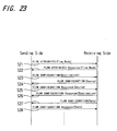
- the transmission takes place under the control of the computer unit 20, it is performed, for example, in the control sequence shown in Figure 25 .
- the computer unit 20 transmits first the transmission attributes commands S31 and S32 for examining the flow control mode to the playback unit 2 and the recording unit 3.
- the respective units 2 and 3 transmit to the computer unit 20 the transmission attributes commands S33 and S34 to which data on possible modes by the respective units are added.
- the transmission attributes commands S31 and S32 on this occasion are composed, as shown in Figure 26 for example, so that it may be clear to be controlled under another terminal by adding ID of the computer unit 20.
- the computer unit 20 transmits to the recording unit 3 a command S35 for directing the mode selected among those examined modes, and the recording unit 3 transmits that direction to the playback unit 2 as a command S36.
- the playback unit 2 transmits a command S37 as a response thereto to the recording unit 3 which transmits further to the computer unit 20 a command S38 as a response thereto.
- the audio signal begins to be transmitted from the playback unit 2 to the recording unit 3.
- the recording unit 3 transmits the transmission setting command S39 for rate control.
- the playback unit 2 receives this transmission setting command S39, it transmits to the recording unit 3 a response command S40 to that command and also adjusts finely the reproduction rate to such conditions as directed by that command.
- the terminal unit is herein the computer unit, an exclusive control unit for directing the recording and reproduction may be employed.
- the other audio equipment such as the amplifying unit shown in Figure 1 may also be employed as the control unit.
- the present invention is not limited thereto and widely applicable to cases where the receiving side is made of an amplifier and the like.
- the present invention is not limited thereto and widely applicable to cases where the audio signal is transmitted between equipments with various formats.
- the transmission format is such that the isochronous transfer packet and the asynchronous transfer packet can be intermingled with each other like the IEEE 1394 format, it can be applied intactly.
- it may be arranged that audio equipments on the reproducing side and recording side are connected with each other by means of a first transmission line and a second transmission line, and the audio signal is transmitted continuously over the first transmission line, whereas the control data, etc. is transmitted over the second transmission line.
- the second transmission line may be a wireless transmission line over which an infrared signal is transmitted by wireless.
- the present invention is not limited thereto and widely applicable to cases where the successive digital signal such as video signal, etc. is transmitted between equipments.
- the transmission of digital signal from the digital signal sender to the digital signal destination can be performed in a more selected among the previously examined modes, thus allowing the digital signal to be transmitted securely in a predetermined mode. Therefore, for example, when the transmitted digital signal is recorded on some medium, it is possible to record in a prepared mode without fail.
- the modes that are set up comprises a mode in which sending out conditions of the digital signal from the digital signal sender is locked, it is ensured to record the digital signal transmitted under the mode-locked conditions and the like without any malfunction.
- the locked mode when comprising the locked mode, if the locked mode includes plural kinds of modes in which the reproduction speed of digital signal sent out of the digital signal sender are different respectively, it will then be possible to transmit and receive the digital signal reproduced at a reproduction speed selected among plural prepared reproduction speed and locked.
- the illustrative digital signal transmission method adds the flag indicating that the transmission rate is being adjusted based on the command from digital signal destination to the digital signal sent out of the digital signal sender, it is possible for the destination to check the flag and make the processing to eliminate the jitters or the like by the fine adjustment of transmission rate.
Landscapes
- Engineering & Computer Science (AREA)
- Signal Processing (AREA)
- Multimedia (AREA)
- Computer Networks & Wireless Communication (AREA)
- Signal Processing For Digital Recording And Reproducing (AREA)
- Communication Control (AREA)
- Small-Scale Networks (AREA)
Priority Applications (1)
| Application Number | Priority Date | Filing Date | Title |
|---|---|---|---|
| EP10179522A EP2270808A3 (en) | 1999-01-27 | 2000-01-26 | Digital signal transmission, computer program product, and recording medium |
Applications Claiming Priority (2)
| Application Number | Priority Date | Filing Date | Title |
|---|---|---|---|
| JP11019153A JP2000215598A (ja) | 1999-01-27 | 1999-01-27 | デジタル信号伝送方法、デジタル信号伝送システム、デジタル信号伝送装置及び記録媒体 |
| JP1915399 | 1999-01-27 |
Related Child Applications (1)
| Application Number | Title | Priority Date | Filing Date |
|---|---|---|---|
| EP10179522.7 Division-Into | 2010-09-24 |
Publications (3)
| Publication Number | Publication Date |
|---|---|
| EP1024493A2 EP1024493A2 (en) | 2000-08-02 |
| EP1024493A3 EP1024493A3 (en) | 2004-06-09 |
| EP1024493B1 true EP1024493B1 (en) | 2013-06-26 |
Family
ID=11991491
Family Applications (2)
| Application Number | Title | Priority Date | Filing Date |
|---|---|---|---|
| EP00300576.6A Expired - Lifetime EP1024493B1 (en) | 1999-01-27 | 2000-01-26 | Digital signal transmission, computer program product, and recording medium |
| EP10179522A Ceased EP2270808A3 (en) | 1999-01-27 | 2000-01-26 | Digital signal transmission, computer program product, and recording medium |
Family Applications After (1)
| Application Number | Title | Priority Date | Filing Date |
|---|---|---|---|
| EP10179522A Ceased EP2270808A3 (en) | 1999-01-27 | 2000-01-26 | Digital signal transmission, computer program product, and recording medium |
Country Status (7)
| Country | Link |
|---|---|
| US (4) | US6788653B1 (https=) |
| EP (2) | EP1024493B1 (https=) |
| JP (1) | JP2000215598A (https=) |
| KR (1) | KR100614427B1 (https=) |
| CN (1) | CN1134930C (https=) |
| ID (1) | ID24534A (https=) |
| TW (1) | TW453085B (https=) |
Families Citing this family (23)
| Publication number | Priority date | Publication date | Assignee | Title |
|---|---|---|---|---|
| CN1214588C (zh) * | 1999-05-25 | 2005-08-10 | 索尼公司 | 传送方法、传送装置及传送系统 |
| US7042896B1 (en) * | 1999-07-26 | 2006-05-09 | Samsung Electronics Co. Ltd. | Method for managing a digital interface connection |
| US7068674B1 (en) | 1999-08-23 | 2006-06-27 | Lg Electronics Inc. | Method of controlling connection between nodes in digital interface |
| KR100620018B1 (ko) * | 1999-10-12 | 2006-09-06 | 엘지전자 주식회사 | 영상기기의 링크 제어장치 |
| KR100424481B1 (ko) * | 2000-06-24 | 2004-03-22 | 엘지전자 주식회사 | 디지털 방송 부가서비스 정보의 기록 재생장치 및 방법과그에 따른 기록매체 |
| JP3952950B2 (ja) * | 2001-04-25 | 2007-08-01 | ソニー株式会社 | ストリームデータを送信するデータ送信方法及び装置 |
| JP4166964B2 (ja) | 2001-05-17 | 2008-10-15 | パイオニア株式会社 | 送信装置及びその制御方法、受信装置及びその制御方法 |
| DE10129108A1 (de) * | 2001-06-16 | 2003-01-02 | Harman Becker Automotive Sys | Verfahren und Schaltungsanordnung zur Datenübertragung |
| JP3873821B2 (ja) * | 2001-06-19 | 2007-01-31 | ソニー株式会社 | 信号再生装置および信号再生方法 |
| DE60142188D1 (de) | 2001-10-08 | 2010-07-01 | Nokia Corp | Dienst- und fähigkeitsverhandlung in einem netzwerk unter verwendung eines einzelbezifferungsschemas |
| CN1656746A (zh) * | 2002-05-31 | 2005-08-17 | 松下电器产业株式会社 | 数据转发方法以及装置 |
| JP2004118242A (ja) | 2002-09-20 | 2004-04-15 | Pioneer Electronic Corp | 状態告知装置、状態告知方法及び状態告知用プログラム |
| KR100920654B1 (ko) * | 2002-12-09 | 2009-10-09 | 엘지전자 주식회사 | 대화형 광디스크 장치에서의 재생 제어방법 |
| KR100953637B1 (ko) | 2003-07-07 | 2010-04-20 | 엘지전자 주식회사 | 광디스크 및 광디스크의 디스크정보 기록방법 |
| US7791639B2 (en) | 2003-12-17 | 2010-09-07 | Canon Kabushiki Kaisha | Control apparatus, video processing apparatus, and control method thereof |
| JP4599056B2 (ja) * | 2003-12-17 | 2010-12-15 | キヤノン株式会社 | 制御装置及び映像処理装置 |
| JP2005243159A (ja) * | 2004-02-27 | 2005-09-08 | Canon Inc | データ出力装置及び制御方法 |
| KR100792983B1 (ko) * | 2005-10-11 | 2008-01-08 | 엘지전자 주식회사 | 디지털 방송 처리방법 |
| JP4525569B2 (ja) * | 2005-11-21 | 2010-08-18 | トヨタ自動車株式会社 | 通信装置 |
| WO2010085908A1 (zh) * | 2009-02-01 | 2010-08-05 | 华为技术有限公司 | 用户设备接入方法及系统和网络接入设备 |
| JP2011041229A (ja) | 2009-08-18 | 2011-02-24 | Sony Corp | 送信装置、受信装置、無線装置および送信装置における伝送モード制御方法 |
| US9848253B2 (en) * | 2014-03-03 | 2017-12-19 | Sony Corporation | Information processing apparatus, information processing method, and program |
| US11800324B2 (en) * | 2020-12-31 | 2023-10-24 | Andrew Lyle GELTZ | Apparatuses, computer-implemented methods, and computer program products for improved data transmission and tracking |
Family Cites Families (32)
| Publication number | Priority date | Publication date | Assignee | Title |
|---|---|---|---|---|
| US4365313A (en) * | 1980-04-11 | 1982-12-21 | Sony Corporation | Cue control apparatus |
| US4394745A (en) * | 1980-04-11 | 1983-07-19 | Sony Corporation | Video editing apparatus |
| US6487362B1 (en) * | 1991-08-19 | 2002-11-26 | Index Systems, Inc. | Enhancing operations of video tape cassette players |
| US5574934A (en) * | 1993-11-24 | 1996-11-12 | Intel Corporation | Preemptive priority-based transmission of signals using virtual channels |
| US5524110A (en) * | 1993-11-24 | 1996-06-04 | Intel Corporation | Conferencing over multiple transports |
| EP0661880B1 (en) * | 1993-12-29 | 2003-03-12 | Canon Kabushiki Kaisha | Communications apparatus for multimedia information |
| US6292181B1 (en) * | 1994-09-02 | 2001-09-18 | Nec Corporation | Structure and method for controlling a host computer using a remote hand-held interface device |
| JPH08124291A (ja) | 1994-10-21 | 1996-05-17 | Sony Corp | ディスクドライブ装置 |
| US5933430A (en) * | 1995-08-12 | 1999-08-03 | Sony Corporation | Data communication method |
| JP3870436B2 (ja) | 1995-11-02 | 2007-01-17 | ソニー株式会社 | 情報信号記録機器及び通信方法 |
| JPH09161350A (ja) | 1995-12-01 | 1997-06-20 | Sony Corp | 情報信号再生装置及びその再生速度設定方法 |
| CZ204098A3 (cs) * | 1996-01-03 | 1998-10-14 | International Business Machine Corporation | Robustní způsob a zařízení umožňující bezdrátovou optickou komunikaci ve více režimech |
| DE69638175D1 (de) | 1996-02-09 | 2010-06-10 | Level One Comm Inc | Zwischenverstärker mit automatischer geschwindigkeitsumschaltung |
| EP0816875A1 (de) * | 1996-06-28 | 1998-01-07 | Alusuisse Technology & Management AG | Reflektor mit reflexionserhöhendem Schichtverbund |
| JPH1065718A (ja) | 1996-08-23 | 1998-03-06 | Sony Corp | データ伝送方法及び装置 |
| JPH1065758A (ja) | 1996-08-23 | 1998-03-06 | Sony Corp | データ伝送方法及び装置 |
| EP0828394B1 (en) * | 1996-09-06 | 2006-05-03 | Samsung Electronics Co., Ltd. | A device and method for converting data transfer rate in communication of digital audio/video data |
| EP0841776A1 (en) | 1996-11-12 | 1998-05-13 | Sony Corporation | Communication methods and electronic apparatus thereof |
| US6215793B1 (en) * | 1996-11-12 | 2001-04-10 | Alcatel | Initialization protocol for adaptive data rates, and related transceiver |
| JPH10173727A (ja) | 1996-12-06 | 1998-06-26 | Yazaki Corp | データ送信装置、データ受信装置、データ通信装置、データ送信方法、データ受信方法、及びデータ通信方法 |
| JP3529574B2 (ja) | 1997-02-07 | 2004-05-24 | 株式会社東芝 | ディジタルインターフェースを有する装置及びディジタルインターフェース方法 |
| JP3860878B2 (ja) | 1997-04-11 | 2006-12-20 | 松下電器産業株式会社 | データ受信装置およびデータ伝送システム |
| JP3927647B2 (ja) * | 1997-04-21 | 2007-06-13 | キヤノン株式会社 | 情報処理装置、情報処理方法及び情報処理システム |
| JP3450662B2 (ja) * | 1997-08-14 | 2003-09-29 | パイオニア株式会社 | 情報記録媒体、その再生装置及び方法並びにその記録装置及び方法 |
| US6285659B1 (en) * | 1997-09-10 | 2001-09-04 | Level One Communications, Inc. | Automatic protocol selection mechanism |
| JP4019481B2 (ja) | 1998-01-23 | 2007-12-12 | ソニー株式会社 | 情報処理装置および方法、情報処理システム、並びに提供媒体 |
| US6470021B1 (en) * | 1998-01-27 | 2002-10-22 | Alcatel Internetworking (Pe), Inc. | Computer network switch with parallel access shared memory architecture |
| US6556589B2 (en) * | 1998-04-17 | 2003-04-29 | Advanced Micro Devices, Inc. | Network transceiver for steering network data to selected paths based on determined link speeds |
| US6272170B1 (en) * | 1998-07-09 | 2001-08-07 | Conexant Systems, Inc. | Method and apparatus for reducing start-up latency in a data transmission system |
| US6160639A (en) * | 1998-09-23 | 2000-12-12 | Motorola, Inc. | Method and system for negotiating transmitting and receiving modes for transmitting facsimile data via a medium having a variable data transmission time |
| US6317417B1 (en) * | 1998-10-05 | 2001-11-13 | Compaq Computer Corporation | Method and apparatus for dynamic signal modification on a parallel bus |
| US6854109B2 (en) * | 2001-06-07 | 2005-02-08 | International Business Machines Corporation | Tool for converting .MAP file formats |
-
1999
- 1999-01-27 JP JP11019153A patent/JP2000215598A/ja active Pending
-
2000
- 2000-01-24 ID IDP20000049A patent/ID24534A/id unknown
- 2000-01-25 TW TW089101204A patent/TW453085B/zh not_active IP Right Cessation
- 2000-01-25 US US09/490,827 patent/US6788653B1/en not_active Expired - Lifetime
- 2000-01-26 EP EP00300576.6A patent/EP1024493B1/en not_active Expired - Lifetime
- 2000-01-26 KR KR1020000003677A patent/KR100614427B1/ko not_active Expired - Lifetime
- 2000-01-26 EP EP10179522A patent/EP2270808A3/en not_active Ceased
- 2000-01-27 CN CNB001048732A patent/CN1134930C/zh not_active Expired - Lifetime
-
2006
- 2006-08-02 US US11/497,862 patent/USRE43271E1/en not_active Expired - Lifetime
-
2012
- 2012-02-10 US US13/370,406 patent/USRE43962E1/en not_active Expired - Lifetime
- 2012-12-27 US US13/728,776 patent/USRE45120E1/en not_active Expired - Lifetime
Also Published As
| Publication number | Publication date |
|---|---|
| USRE45120E1 (en) | 2014-09-09 |
| EP1024493A3 (en) | 2004-06-09 |
| CN1264973A (zh) | 2000-08-30 |
| KR20000053624A (ko) | 2000-08-25 |
| KR100614427B1 (ko) | 2006-08-22 |
| USRE43271E1 (en) | 2012-03-27 |
| EP2270808A3 (en) | 2011-09-21 |
| ID24534A (id) | 2000-07-27 |
| TW453085B (en) | 2001-09-01 |
| EP2270808A2 (en) | 2011-01-05 |
| CN1134930C (zh) | 2004-01-14 |
| JP2000215598A (ja) | 2000-08-04 |
| US6788653B1 (en) | 2004-09-07 |
| EP1024493A2 (en) | 2000-08-02 |
| USRE43962E1 (en) | 2013-02-05 |
Similar Documents
| Publication | Publication Date | Title |
|---|---|---|
| USRE43962E1 (en) | Digital signal transmission method, digital signal transmission system, digital signal transmitting apparatus and recording medium | |
| US6944180B1 (en) | Digital signal processing device and method, digital signal processing system | |
| JPWO2000072552A1 (ja) | ディジタル信号処理装置及び方法、ディジタル信号処理システム | |
| EP1185034B1 (en) | Network error display apparatus and error detection display method | |
| EP1085709B1 (en) | Data transmission in a serial IEEE 1394 bus | |
| KR20000022836A (ko) | 정보처리 장치 및 방법과 제공매체 | |
| EP1085724B1 (en) | Communication system in audio and music data transmission | |
| EP1276278A1 (en) | Data transmission method and data transmission device | |
| JP2000151720A (ja) | データ処理回路およびデータ伝送システム | |
| JP3676618B2 (ja) | パケット転送装置、及びデータ記録媒体 | |
| JP2000151719A (ja) | データ処理回路およびデータ伝送システム | |
| US20020073169A1 (en) | Information processing apparatus, information processing system and method thereof | |
| JPH11205391A (ja) | ディジタル信号伝送装置及びディジタル信号伝送システム | |
| JP2001358800A (ja) | 情報処理システム及び情報処理装置並びにそれらの方法 | |
| JP2002056589A (ja) | 情報記録装置 | |
| JPWO2000072551A1 (ja) | 通信方法、通信システム及び電子機器 | |
| JP2000253029A (ja) | データ送受信システム |
Legal Events
| Date | Code | Title | Description |
|---|---|---|---|
| PUAI | Public reference made under article 153(3) epc to a published international application that has entered the european phase |
Free format text: ORIGINAL CODE: 0009012 |
|
| AK | Designated contracting states |
Kind code of ref document: A2 Designated state(s): AT BE CH CY DE DK ES FI FR GB GR IE IT LI LU MC NL PT SE |
|
| AX | Request for extension of the european patent |
Free format text: AL;LT;LV;MK;RO;SI |
|
| PUAL | Search report despatched |
Free format text: ORIGINAL CODE: 0009013 |
|
| AK | Designated contracting states |
Kind code of ref document: A3 Designated state(s): AT BE CH CY DE DK ES FI FR GB GR IE IT LI LU MC NL PT SE |
|
| AX | Request for extension of the european patent |
Extension state: AL LT LV MK RO SI |
|
| RIC1 | Information provided on ipc code assigned before grant |
Ipc: 7G 11B 27/034 B Ipc: 7G 11B 27/10 B Ipc: 7G 06F 13/42 B Ipc: 7G 11B 20/10 B Ipc: 7G 11B 27/30 A Ipc: 7H 04L 12/64 B |
|
| 17P | Request for examination filed |
Effective date: 20041123 |
|
| AKX | Designation fees paid |
Designated state(s): DE FR GB |
|
| GRAP | Despatch of communication of intention to grant a patent |
Free format text: ORIGINAL CODE: EPIDOSNIGR1 |
|
| GRAS | Grant fee paid |
Free format text: ORIGINAL CODE: EPIDOSNIGR3 |
|
| GRAA | (expected) grant |
Free format text: ORIGINAL CODE: 0009210 |
|
| AK | Designated contracting states |
Kind code of ref document: B1 Designated state(s): DE FR GB |
|
| REG | Reference to a national code |
Ref country code: GB Ref legal event code: FG4D |
|
| REG | Reference to a national code |
Ref country code: DE Ref legal event code: R096 Ref document number: 60048091 Country of ref document: DE Effective date: 20130822 |
|
| PLBE | No opposition filed within time limit |
Free format text: ORIGINAL CODE: 0009261 |
|
| STAA | Information on the status of an ep patent application or granted ep patent |
Free format text: STATUS: NO OPPOSITION FILED WITHIN TIME LIMIT |
|
| 26N | No opposition filed |
Effective date: 20140327 |
|
| REG | Reference to a national code |
Ref country code: DE Ref legal event code: R097 Ref document number: 60048091 Country of ref document: DE Effective date: 20140327 |
|
| REG | Reference to a national code |
Ref country code: FR Ref legal event code: PLFP Year of fee payment: 17 |
|
| REG | Reference to a national code |
Ref country code: FR Ref legal event code: PLFP Year of fee payment: 18 |
|
| REG | Reference to a national code |
Ref country code: FR Ref legal event code: PLFP Year of fee payment: 19 |
|
| REG | Reference to a national code |
Ref country code: DE Ref legal event code: R081 Ref document number: 60048091 Country of ref document: DE Owner name: WI-FI ONE TECHNOLOGIES INTERNATIONAL LIMITED, IE Free format text: FORMER OWNER: SONY CORPORATION, TOKIO/TOKYO, JP |
|
| REG | Reference to a national code |
Ref country code: GB Ref legal event code: 732E Free format text: REGISTERED BETWEEN 20190124 AND 20190130 |
|
| PGFP | Annual fee paid to national office [announced via postgrant information from national office to epo] |
Ref country code: FR Payment date: 20190128 Year of fee payment: 20 Ref country code: DE Payment date: 20190131 Year of fee payment: 20 Ref country code: GB Payment date: 20190130 Year of fee payment: 20 |
|
| REG | Reference to a national code |
Ref country code: DE Ref legal event code: R071 Ref document number: 60048091 Country of ref document: DE |
|
| REG | Reference to a national code |
Ref country code: GB Ref legal event code: PE20 Expiry date: 20200125 |
|
| PG25 | Lapsed in a contracting state [announced via postgrant information from national office to epo] |
Ref country code: GB Free format text: LAPSE BECAUSE OF EXPIRATION OF PROTECTION Effective date: 20200125 |