EP1022196B1 - Gassack-Rückhaltemodul - Google Patents
Gassack-Rückhaltemodul Download PDFInfo
- Publication number
- EP1022196B1 EP1022196B1 EP00110212A EP00110212A EP1022196B1 EP 1022196 B1 EP1022196 B1 EP 1022196B1 EP 00110212 A EP00110212 A EP 00110212A EP 00110212 A EP00110212 A EP 00110212A EP 1022196 B1 EP1022196 B1 EP 1022196B1
- Authority
- EP
- European Patent Office
- Prior art keywords
- gas bag
- restraint module
- module according
- accommodation part
- bag restraint
- Prior art date
- Legal status (The legal status is an assumption and is not a legal conclusion. Google has not performed a legal analysis and makes no representation as to the accuracy of the status listed.)
- Expired - Lifetime
Links
Images


Classifications
-
- B—PERFORMING OPERATIONS; TRANSPORTING
- B60—VEHICLES IN GENERAL
- B60R—VEHICLES, VEHICLE FITTINGS, OR VEHICLE PARTS, NOT OTHERWISE PROVIDED FOR
- B60R21/00—Arrangements or fittings on vehicles for protecting or preventing injuries to occupants or pedestrians in case of accidents or other traffic risks
- B60R21/02—Occupant safety arrangements or fittings, e.g. crash pads
- B60R21/16—Inflatable occupant restraints or confinements designed to inflate upon impact or impending impact, e.g. air bags
- B60R21/20—Arrangements for storing inflatable members in their non-use or deflated condition; Arrangement or mounting of air bag modules or components
- B60R21/217—Inflation fluid source retainers, e.g. reaction canisters; Connection of bags, covers, diffusers or inflation fluid sources therewith or together
- B60R21/2171—Inflation fluid source retainers, e.g. reaction canisters; Connection of bags, covers, diffusers or inflation fluid sources therewith or together specially adapted for elongated cylindrical or bottle-like inflators with a symmetry axis perpendicular to the main direction of bag deployment, e.g. extruded reaction canisters
-
- B—PERFORMING OPERATIONS; TRANSPORTING
- B60—VEHICLES IN GENERAL
- B60R—VEHICLES, VEHICLE FITTINGS, OR VEHICLE PARTS, NOT OTHERWISE PROVIDED FOR
- B60R21/00—Arrangements or fittings on vehicles for protecting or preventing injuries to occupants or pedestrians in case of accidents or other traffic risks
- B60R21/02—Occupant safety arrangements or fittings, e.g. crash pads
- B60R21/16—Inflatable occupant restraints or confinements designed to inflate upon impact or impending impact, e.g. air bags
- B60R21/20—Arrangements for storing inflatable members in their non-use or deflated condition; Arrangement or mounting of air bag modules or components
- B60R21/201—Packaging straps or envelopes for inflatable members
Definitions
- the invention relates to an airbag restraint module the features of the preamble of claim 1.
- gas bag restraint modules are known to those skilled in the art the vehicle occupant safety technology known. Usually a so-called gas generator with an pyrotechnic charge used after activation in a very short time Time releases a predetermined gas volume. Most recently however, efforts are increasing to secure gas bag restraint modules create that with a significantly smaller pyrotechnic charge work, since their use in particular with regard to Environmental compatibility is not without problems.
- an airbag restraint module of the type mentioned at the beginning which is adapted to the use of an inflator, the has a compressed gas container, in particular of the "heated gas" type Inflator ".
- EP 0 558 240 A1 there is a Airbag restraint module with a housing, one in this arranged inflator and a gas bag described.
- the Housing has a generally cylindrical receiving part in which the inflator is inserted in the axial direction, and two running in the axial direction, starting from the Mounting part outwardly extending fastening strips.
- the receiving part can be cylindrical or trough-shaped.
- Inflator is a cylindrical pyrotechnic gas generator intended.
- the gas bag can be fastened to the receiving part by inserting a fastening section of the gas bag into an am Receiving part provided mounting groove or by clamping the Fastening section between a separate diffuser and the Take part.
- the cylindrical gas generator is concentric, but at a distance from the receiving part and is arranged either with the help of a screw connection in the axial direction Direction clamped in the receiving part, or it is rotating with Fastening flanges provided with the help of the Receiving part screwed diffuser are fixed.
- the published European patent application EP 0 680 851 A1 describes a gas bag restraint module in which a bottle-like compressed gas container axially into a receiving part is clamped. Additional elastic brackets in which the Pressurized gas container is snapped in, hold the gas generator in radial direction on the receiving part.
- the housing with the Pressurized gas container on the one hand and the mounting frame with the folded gas bag on the other hand form two pre-assembled modules.
- the gas bag restraint module By dividing the gas bag restraint module into two Assemblies that can be preassembled separately result in more Assembly advantages.
- the gas bag restraint module consists of two separately preassembled ones Assemblies, the first of which is the housing with the compressed gas tank and the second the gas bag with its mounting frame is.
- FIGS. 1 to 11 A first embodiment is shown schematically in FIGS. 1 to 11 of a housing 10 of an airbag restraint module.
- This housing 10 has a generally cylindrical receiving part 11 in which a compressed gas container 12 is inserted in the axial direction is, as well as two in the axial direction, starting from the mounting part 11 outwardly extending fastening strips 14th There are two in the receiving part 11 between the fastening strips 14 Through openings 16 are formed.
- each fastening strip 14 is folded twice, so that between those protruding vertically upwards in FIGS. 3 and 4 Sections of the fastening strips 14 a receiving space is trained.
- the fastening strip 14 is a plurality of fastening holes 18 educated.
- the compressed gas bottle 12 contains pressurized gas that after ignition of a pyrotechnic auxiliary charge to activate the Airbag restraint module flows out of this in the area of the head. Furthermore, a chemical reaction of the Pressurized gas initiated, which leads to an increase in the temperature of the released gas and thus leads to an increase in its volume.
- the compressed gas bottle 12 is in the receiving part 11 by means of Press fit held.
- the receiving part 11 has a polygonal cross section, so that the press fit between the Sections of the receiving part 11 with the smallest radial distance formed by the central longitudinal axis and the wall of the gas cylinder is.
- the contact points between the receiving part 11 and the Pressurized gas bottle 12 are indicated by arrows.
- the receiving part 11 has one essentially circular cross-section, so that there is a Contact between the wall of the receiving part 11 and the wall the compressed gas cylinder 12 along a large surface area of the Compressed gas bottle 12 results. Also in this figure are the areas of the Contact between the receiving part 11 and the compressed gas bottle 12 indicated by arrows.
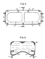
- FIG. 5 schematically shows a mounting frame 40, that for attaching a gas bag 50 to the housing 10 is provided.
- the mounting frame 40 has a general rectangular in shape, and it is along along its longitudinal centerline provided two through openings 42.
- mounting bolts 44 and 46 are provided, some of which, namely the fastening bolts 44, are vertical 5, while others, namely the Bolt 46, extend in the drawing plane of this figure.
- the Fastening frame 40 is together with the fastening bolts 44 or 46 inserted into the interior of the gas bag 50 that the Fastening bolts through openings in the gas bag extend into a blowing opening of the gas bag 50 surrounding fastening section are formed. In this way the mounting frame 40 becomes accurate relative to the gas bag 50 fixed.
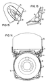
- the gas bag 50 is then over the mounting frame 40 folded so that it has a compact shape and laterally essentially not over the outer edge of the mounting frame 40 stands out. In this folded state the gas bag 50 is fixed so that it is in the further Handling the existing from him and the mounting frame 40 Assembly cannot unfold again.
- a cross section through one folded gas bag 50 and the associated mounting frame 40 is shown in FIG. 6.
- FIGS 7 and 8 are two variants for fixing the Gas bags shown in the collapsed form.
- the gas bag 50 has a rectangular Fixing part 54, one long side of which is fixed to the gas bag 50 connected is; it is preferably sewn to the gas bag 50.
- the other long side of the fixing part 54 is provided with tabs 56, in which openings 58 are formed.
- the one between the two Middle section of the fixing part 54 lying on the longitudinal side is included a line of perforations 60. If the gas bag in the desired, compact shape is folded, it will Fixing part struck over the gas bag, and the openings 58 of the Tabs 56 are hooked into the fastening bolts 44, so that the Airbag 50 is fixed.
- the airbag 50 of a band 65 known to the person skilled in the art in the folded kept compact condition can be made from one Plastic material or another suitable material, for example textile fabrics.
- FIGS. 9 to 11 shown according to the first embodiment after that consisting of the housing 10 and the compressed gas bottle 12 Assembly with the gas bag 50 and the fastening frame 40 existing assembly is assembled.
- the mounting frame 40 is placed together with the gas bag 50 on the housing 10 that the fastening bolts 44 through the openings 18 extend, which are formed in the fastening strip 14.
- On the free ends of the fastening bolts 44 are each a nut screwed.
- the one facing the bottom of the compressed gas container 12 The end face of the receiving part 11 is by means of a base plate 70 closed, which is provided with openings through which the Extension bolts 46 extend through.
- a nut is screwed on, preferably from the same Type like the nuts that are on the mounting bolts 44 are screwed on.
- Pressed retaining nuts are used in the outside Fastening screws are screwed in.
- the holding plate 72 is provided with a holding section that matches the shape of the head is adjusted. Furthermore, the holding section has an opening in which engages an approach of the head of the compressed gas bottle 12. This is can be seen in particular in FIG. 10.
- the bottom plate 70 and the Holding plate 72 are each with a flange 74 with holes 76 provided that for mounting the gas bag restraint module in one Vehicle is provided.
- the design of the gas bag restraint system results in various advantages with regard to the manufacture and assembly of the individual components.
- the housing 10 is preferably based on an extruded profile. This results in a particularly simple manufacture, since apart from the formation of the Bores 18 in the fastening strips 14 and the appropriate length Cutting the extruded profile does not require any processing steps are necessary.
- By the press fit between the receiving part 11 and the compressed gas bottle 12 is in a particularly simple manner in the Housing 10 held. Although actually no additional funds to determine the compressed gas bottle 12 are necessary by the Base plate 70 and the holding plate 72 the security of the down the compressed gas bottle 12 increased.
- the base plate 70 also serves and the holding plate 72 when the housing 10 is not externally sealed is provided as seals for the housing 10 so that a closed space is formed, in which the compressed gas Compressed gas source 12 can flow out.
- the in the mounting frame 40th attached mounting bolts 44 and 46 serve in addition to the Attachment of the mounting frame 40 to the housing 10 and Attachment of the bottom plate 70 and the holding plate 72 also the Fixing the gas bag 50.
- FIGS. 12 to 19 schematically show a second one Embodiment of a gas bag restraint module shown.
- This differs from the first embodiment essentially only characterized in that the receiving part 11 is a trough-like gas bag and has the shape open at the end, that is, the through opening 16 extends along the entire length of the housing 10.
- the same Reference numerals used and in the description of these Components is referred to the explanations for Figures 1 to 11 taken.
- the receiving part 11 Housing elastic, so that the two legs to which the Connect mounting strips 14, movable relative to each other are.
- the dimensions of the compressed gas bottle 12 and the receiving part 11 are adapted to each other so that the compressed gas bottle easily in the Receiving part 11 can be inserted when the fastening strips from the starting position shown in dashed lines in FIG. 12 be separated from each other.
- the attachment strips 14 After the compressed gas bottle 12 in the Mounting part 11 is introduced, the attachment strips 14 released again, and they look due to the elasticity of the Material of the housing 10 to return to the starting position. This is shown in Fig. 12 by the arrows.
- the Outside diameter of the compressed gas bottle 12 is larger than that Inner diameter of the receiving part 11 selected in the starting position, see above that the compressed gas bottle 12 in the receiving part 11 due to the resulting bias is set. Now is the first assembly completely.
- the second assembly the design of which does not differ from the design described above to which first assembly be put on.
- the attachment of the two Assemblies together differ from the explanations above only in that due to the dimensions of the two assemblies relative to each other when screwing the second assembly to the first assembly a clamping force is generated, which the two Fixing strip 14 continues to approach the starting position. This exerts a tensioning effect on the compressed gas cylinder, which is symbolized by the three arrows in FIG. 13.
- the second Assembly works together with the first assembly like one Pipe clamp, inside which the compressed gas bottle 12 is clamped. Due to the polygonal cross-section of the receiving part 11 and The shape of the mounting frame 40 does not exert any direct pressure on it the compressed gas source.
- Receiving part 11 also selected such a polygonal profile be that the mounting frame 40 touches the compressed gas source 12 and sets this together with the receiving part 11, or a circular profile, so that between the receiving part 11 and the mounting frame 40 on one side and the pressurized gas source 12 on the other hand results in a flat clamping effect.
- the first variant of the housing 10 of FIG Airbag restraint module according to the second embodiment is included four screw eyes 80, which are integral with the housing 10 the outside of which are formed. This is particularly advantageous when the housing 10 is made from an extruded profile is.
- screw eyes 80 after mounting the base plate 70 and the holding plate 72 self-tapping screws are screwed in, which together with the fastening bolts 46 the bottom or Set holding plate 70 or 72.
- the one shown in Figure 12 Housing is also provided with three contact surfaces 83 with which the Pressurized gas source is precisely defined and pinched.
- the one in figure 13 shown second variant of the housing 10 is with two Screw eyes 80 provided on the inside of the housing are trained.
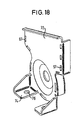
- a gas bag restraint module is shown schematically in FIGS. 14 to 16 according to the second embodiment with a third Variant of the housing 10 shown.
- This housing 10 is outgoing made from a sheet metal part. Because of the better Deformability and machinability of a sheet metal part an extruded profile gives further constructive Possibilities for attaching the bottom plate 70 and Holding plate 72 and for the clamping between the receiving part 11 and the compressed gas source 12.
- the receiving part 11 is in this Variant of the housing 10 provided with abutments 90, their function corresponds to that of the screw eyes 80 of FIG. 13.
- the abutments are each by two circular tabs 92 or 94 formed, seen in the direction of screwing lie one behind the other and relative to each other opposite directions bent out of the material plane are.
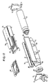
- a gas bag restraint module is shown schematically in FIGS according to the second embodiment with a fourth Variant of the housing 10 shown.
- This variant is also the housing 10 is made from a bent sheet metal part.
- beads 81 are provided, on which the Compressed gas source 12 comes into contact when it is in the housing 10 is clamped.
- Spacer 82 arranged with projections for a clear Angular positioning is provided relative to the receiving part 11 and in same way as the compressed gas source 12 by a clamping action is held. This spacer stabilizes the receiving part 11, improves the definition of the gas bag on the mounting frame 40 and serves as a seal on this side of the compressed gas source 12.
- bending tabs 96 can be used, which the end faces of the receiving part 11 are provided in the Bottom plate 70 or the holding plate 72 formed openings 97th traverse and on the outside of the bottom or holding plate 70 or 72 are bent so that they are fixed.
- Baffle 98 in the area of the head end of the compressed gas source 12 are used. This baffle 98 prevents the Airbag 50 by direct flow from that of the compressed gas source 12 released compressed gas is damaged.
Landscapes
- Engineering & Computer Science (AREA)
- Mechanical Engineering (AREA)
- Air Bags (AREA)
Applications Claiming Priority (5)
| Application Number | Priority Date | Filing Date | Title |
|---|---|---|---|
| DE19532768A DE19532768A1 (de) | 1995-09-05 | 1995-09-05 | Gassack-Rückhaltemodul |
| DE19532768 | 1995-09-05 | ||
| DE29604345U DE29604345U1 (de) | 1995-09-05 | 1996-03-08 | Gassack-Rückhaltemodul |
| DE29604345U | 1996-03-08 | ||
| EP96112727A EP0761506B1 (de) | 1995-09-05 | 1996-08-07 | Gassack-Rückhaltemodul |
Related Parent Applications (2)
| Application Number | Title | Priority Date | Filing Date |
|---|---|---|---|
| EP96112727.1 Division | 1996-08-07 | ||
| EP96112727A Division EP0761506B1 (de) | 1995-09-05 | 1996-08-07 | Gassack-Rückhaltemodul |
Publications (3)
| Publication Number | Publication Date |
|---|---|
| EP1022196A2 EP1022196A2 (de) | 2000-07-26 |
| EP1022196A3 EP1022196A3 (de) | 2000-10-11 |
| EP1022196B1 true EP1022196B1 (de) | 2003-06-18 |
Family
ID=7771327
Family Applications (1)
| Application Number | Title | Priority Date | Filing Date |
|---|---|---|---|
| EP00110212A Expired - Lifetime EP1022196B1 (de) | 1995-09-05 | 1996-08-07 | Gassack-Rückhaltemodul |
Country Status (4)
| Country | Link |
|---|---|
| EP (1) | EP1022196B1 (zh) |
| KR (1) | KR100223117B1 (zh) |
| DE (4) | DE19532768A1 (zh) |
| TW (1) | TW336198B (zh) |
Families Citing this family (7)
| Publication number | Priority date | Publication date | Assignee | Title |
|---|---|---|---|---|
| EP0794091B1 (de) * | 1996-03-08 | 2001-05-16 | TRW Occupant Restraint Systems GmbH & Co. KG | Gassack-Rückhaltemodul |
| DE29612777U1 (de) * | 1996-07-23 | 1996-11-21 | Trw Repa Gmbh | Gassack-Modul für ein Fahrzeuginsassen-Rückhaltesystem |
| DE29701063U1 (de) * | 1997-01-22 | 1997-05-22 | Trw Occupant Restraint Systems Gmbh, 73551 Alfdorf | Gassack-Modul |
| DE19928696B4 (de) * | 1999-06-23 | 2005-06-16 | Autoliv Development Ab | Airbaganordnung mit einem Biegeflächen aufweisenden Container |
| DE20112313U1 (de) | 2001-07-26 | 2001-11-29 | TRW Occupant Restraint Systems GmbH & Co. KG, 73553 Alfdorf | Baugruppe aus zylindrischem Gasgenerator, Gehäuse und Halteteil |
| DE102004007415B4 (de) * | 2004-02-16 | 2006-02-09 | Key Safety Systems, Inc.(n.d.Ges.d.Staates Delaware), Sterling Heights | Befestigung für einen Gassack |
| DE202006006903U1 (de) * | 2006-04-26 | 2007-09-06 | Autoliv Development Ab | Banderole und Airbageinheit mit Banderole |
Family Cites Families (5)
| Publication number | Priority date | Publication date | Assignee | Title |
|---|---|---|---|---|
| US5058919A (en) * | 1990-06-15 | 1991-10-22 | Trw Vehicle Safety Systems, Inc | Air bag module construction and assembly technique |
| US5332256A (en) * | 1992-02-24 | 1994-07-26 | Morton International, Inc. | Continuous circumference diffuser reaction canister |
| US5263739A (en) * | 1992-12-28 | 1993-11-23 | General Motors Corporation | Air bag module |
| EP0620140B2 (en) * | 1993-04-12 | 2001-01-24 | Autoliv Asp, Inc. | Inflatable restraint system reaction canister |
| WO1994025313A1 (en) * | 1993-04-30 | 1994-11-10 | Alliedsignal Inc. | Air bag module with extruded housing |
-
1995
- 1995-09-05 DE DE19532768A patent/DE19532768A1/de not_active Withdrawn
-
1996
- 1996-03-08 DE DE29604345U patent/DE29604345U1/de not_active Expired - Lifetime
- 1996-08-07 DE DE59610546T patent/DE59610546D1/de not_active Expired - Fee Related
- 1996-08-07 EP EP00110212A patent/EP1022196B1/de not_active Expired - Lifetime
- 1996-08-07 DE DE59607992T patent/DE59607992D1/de not_active Expired - Lifetime
- 1996-08-29 KR KR1019960036267A patent/KR100223117B1/ko not_active IP Right Cessation
-
1997
- 1997-03-03 TW TW086102698A patent/TW336198B/zh active
Also Published As
| Publication number | Publication date |
|---|---|
| DE59610546D1 (de) | 2003-07-24 |
| EP1022196A2 (de) | 2000-07-26 |
| KR100223117B1 (ko) | 1999-10-15 |
| DE29604345U1 (de) | 1996-07-18 |
| KR970015273A (ko) | 1997-04-28 |
| DE19532768A1 (de) | 1997-03-06 |
| EP1022196A3 (de) | 2000-10-11 |
| TW336198B (en) | 1998-07-11 |
| DE59607992D1 (de) | 2001-11-29 |
Similar Documents
| Publication | Publication Date | Title |
|---|---|---|
| EP0761506B1 (de) | Gassack-Rückhaltemodul | |
| EP1108626B1 (de) | Gassack-Rückhaltemodul | |
| DE69517092T2 (de) | Luftsackmodul | |
| DE69300496T2 (de) | Reaktionsdose mit kreisförmigem Diffusor. | |
| DE10224726B4 (de) | Airbag-Halteklammer | |
| DE29706246U1 (de) | Gassack-Modul für ein Fahrzeuginsassen-Rückhaltesystem | |
| EP2203330A1 (de) | Airbagmodul | |
| DE20022020U1 (de) | Gassackmodul | |
| EP2134575B1 (de) | Gassackanordnungen für ein fahrzeuginsassen-rückhaltesystem | |
| EP0792773A1 (de) | Airbagmodul mit einem aus mehreren voneinander trennbaren Gehäuseteilen bestehenden Gehäuse | |
| EP0857626A2 (de) | Baugruppe aus einem Gasgenerator und einem Abströmrohr für ein Fahrzeuginsassen-Rückhaltesystem | |
| DE4309925A1 (de) | Airbag-Einheit | |
| DE19508533C2 (de) | Airbagmodul für Kraftfahrzeuge | |
| EP1022196B1 (de) | Gassack-Rückhaltemodul | |
| DE69514626T2 (de) | Entfaltungsdeckel zum Gebrauch in einer Fahrzeuginsassen-Rückhaltevorrichtung | |
| EP0794091B1 (de) | Gassack-Rückhaltemodul | |
| DE19621397B4 (de) | Airbagmodul | |
| EP1533198A1 (de) | Gassackmodul | |
| DE69408200T2 (de) | Verfahren zum Befestigen von Luftsackkissen | |
| DE19710063B4 (de) | Airbag mit Gaserzeuger | |
| EP0822124A1 (de) | Gassack-Modul für ein Fahrzeuginsassen-Rückhaltesystem | |
| DE4335831A1 (de) | Struktur zum Anbringen einer Aufblaseinrichtung in einer Luftsackeinrichtung | |
| EP1060957B1 (de) | Baueinheit für ein Gassack-Modul und Gassack-Modul | |
| EP1088711A2 (de) | Beifahrer-Airbagmodul für Kraftfahrzeuge | |
| DE29801871U1 (de) | Gassack-Modul für einen Kopfschutz-Gassack |
Legal Events
| Date | Code | Title | Description |
|---|---|---|---|
| PUAI | Public reference made under article 153(3) epc to a published international application that has entered the european phase |
Free format text: ORIGINAL CODE: 0009012 |
|
| AC | Divisional application: reference to earlier application |
Ref document number: 761506 Country of ref document: EP |
|
| AK | Designated contracting states |
Kind code of ref document: A2 Designated state(s): DE ES FR GB IT SE |
|
| RIN1 | Information on inventor provided before grant (corrected) |
Inventor name: LUTZ, JOACHIM |
|
| PUAL | Search report despatched |
Free format text: ORIGINAL CODE: 0009013 |
|
| AK | Designated contracting states |
Kind code of ref document: A3 Designated state(s): DE ES FR GB IT SE |
|
| 17P | Request for examination filed |
Effective date: 20010102 |
|
| AKX | Designation fees paid |
Free format text: DE ES FR GB IT SE |
|
| 17Q | First examination report despatched |
Effective date: 20020503 |
|
| GRAH | Despatch of communication of intention to grant a patent |
Free format text: ORIGINAL CODE: EPIDOS IGRA |
|
| GRAH | Despatch of communication of intention to grant a patent |
Free format text: ORIGINAL CODE: EPIDOS IGRA |
|
| GRAA | (expected) grant |
Free format text: ORIGINAL CODE: 0009210 |
|
| AC | Divisional application: reference to earlier application |
Ref document number: 0761506 Country of ref document: EP Kind code of ref document: P |
|
| AK | Designated contracting states |
Designated state(s): DE ES FR GB IT SE |
|
| REG | Reference to a national code |
Ref country code: GB Ref legal event code: FG4D Free format text: NOT ENGLISH |
|
| PGFP | Annual fee paid to national office [announced via postgrant information from national office to epo] |
Ref country code: GB Payment date: 20030702 Year of fee payment: 8 |
|
| REF | Corresponds to: |
Ref document number: 59610546 Country of ref document: DE Date of ref document: 20030724 Kind code of ref document: P |
|
| PG25 | Lapsed in a contracting state [announced via postgrant information from national office to epo] |
Ref country code: SE Free format text: LAPSE BECAUSE OF FAILURE TO SUBMIT A TRANSLATION OF THE DESCRIPTION OR TO PAY THE FEE WITHIN THE PRESCRIBED TIME-LIMIT Effective date: 20030918 |
|
| GBT | Gb: translation of ep patent filed (gb section 77(6)(a)/1977) |
Effective date: 20031030 |
|
| REG | Reference to a national code |
Ref country code: ES Ref legal event code: FG2A Ref document number: 2200755 Country of ref document: ES Kind code of ref document: T3 |
|
| ET | Fr: translation filed | ||
| PLBE | No opposition filed within time limit |
Free format text: ORIGINAL CODE: 0009261 |
|
| STAA | Information on the status of an ep patent application or granted ep patent |
Free format text: STATUS: NO OPPOSITION FILED WITHIN TIME LIMIT |
|
| 26N | No opposition filed |
Effective date: 20040319 |
|
| PGFP | Annual fee paid to national office [announced via postgrant information from national office to epo] |
Ref country code: FR Payment date: 20040804 Year of fee payment: 9 |
|
| PG25 | Lapsed in a contracting state [announced via postgrant information from national office to epo] |
Ref country code: GB Free format text: LAPSE BECAUSE OF NON-PAYMENT OF DUE FEES Effective date: 20040807 |
|
| PGFP | Annual fee paid to national office [announced via postgrant information from national office to epo] |
Ref country code: ES Payment date: 20040825 Year of fee payment: 9 |
|
| GBPC | Gb: european patent ceased through non-payment of renewal fee |
Effective date: 20040807 |
|
| PG25 | Lapsed in a contracting state [announced via postgrant information from national office to epo] |
Ref country code: IT Free format text: LAPSE BECAUSE OF NON-PAYMENT OF DUE FEES Effective date: 20050807 |
|
| PG25 | Lapsed in a contracting state [announced via postgrant information from national office to epo] |
Ref country code: ES Free format text: LAPSE BECAUSE OF NON-PAYMENT OF DUE FEES Effective date: 20050808 |
|
| PG25 | Lapsed in a contracting state [announced via postgrant information from national office to epo] |
Ref country code: FR Free format text: LAPSE BECAUSE OF NON-PAYMENT OF DUE FEES Effective date: 20060428 |
|
| REG | Reference to a national code |
Ref country code: FR Ref legal event code: ST Effective date: 20060428 |
|
| REG | Reference to a national code |
Ref country code: ES Ref legal event code: FD2A Effective date: 20050808 |
|
| PGFP | Annual fee paid to national office [announced via postgrant information from national office to epo] |
Ref country code: DE Payment date: 20080829 Year of fee payment: 13 |
|
| PG25 | Lapsed in a contracting state [announced via postgrant information from national office to epo] |
Ref country code: DE Free format text: LAPSE BECAUSE OF NON-PAYMENT OF DUE FEES Effective date: 20100302 |