EP1022196B1 - Air bag restraint module - Google Patents
Air bag restraint module Download PDFInfo
- Publication number
- EP1022196B1 EP1022196B1 EP00110212A EP00110212A EP1022196B1 EP 1022196 B1 EP1022196 B1 EP 1022196B1 EP 00110212 A EP00110212 A EP 00110212A EP 00110212 A EP00110212 A EP 00110212A EP 1022196 B1 EP1022196 B1 EP 1022196B1
- Authority
- EP
- European Patent Office
- Prior art keywords
- gas bag
- restraint module
- module according
- accommodation part
- bag restraint
- Prior art date
- Legal status (The legal status is an assumption and is not a legal conclusion. Google has not performed a legal analysis and makes no representation as to the accuracy of the status listed.)
- Expired - Lifetime
Links
Images


Classifications
-
- B—PERFORMING OPERATIONS; TRANSPORTING
- B60—VEHICLES IN GENERAL
- B60R—VEHICLES, VEHICLE FITTINGS, OR VEHICLE PARTS, NOT OTHERWISE PROVIDED FOR
- B60R21/00—Arrangements or fittings on vehicles for protecting or preventing injuries to occupants or pedestrians in case of accidents or other traffic risks
- B60R21/02—Occupant safety arrangements or fittings, e.g. crash pads
- B60R21/16—Inflatable occupant restraints or confinements designed to inflate upon impact or impending impact, e.g. air bags
- B60R21/20—Arrangements for storing inflatable members in their non-use or deflated condition; Arrangement or mounting of air bag modules or components
- B60R21/217—Inflation fluid source retainers, e.g. reaction canisters; Connection of bags, covers, diffusers or inflation fluid sources therewith or together
- B60R21/2171—Inflation fluid source retainers, e.g. reaction canisters; Connection of bags, covers, diffusers or inflation fluid sources therewith or together specially adapted for elongated cylindrical or bottle-like inflators with a symmetry axis perpendicular to the main direction of bag deployment, e.g. extruded reaction canisters
-
- B—PERFORMING OPERATIONS; TRANSPORTING
- B60—VEHICLES IN GENERAL
- B60R—VEHICLES, VEHICLE FITTINGS, OR VEHICLE PARTS, NOT OTHERWISE PROVIDED FOR
- B60R21/00—Arrangements or fittings on vehicles for protecting or preventing injuries to occupants or pedestrians in case of accidents or other traffic risks
- B60R21/02—Occupant safety arrangements or fittings, e.g. crash pads
- B60R21/16—Inflatable occupant restraints or confinements designed to inflate upon impact or impending impact, e.g. air bags
- B60R21/20—Arrangements for storing inflatable members in their non-use or deflated condition; Arrangement or mounting of air bag modules or components
- B60R21/201—Packaging straps or envelopes for inflatable members
Definitions
- the invention relates to an airbag restraint module the features of the preamble of claim 1.
- gas bag restraint modules are known to those skilled in the art the vehicle occupant safety technology known. Usually a so-called gas generator with an pyrotechnic charge used after activation in a very short time Time releases a predetermined gas volume. Most recently however, efforts are increasing to secure gas bag restraint modules create that with a significantly smaller pyrotechnic charge work, since their use in particular with regard to Environmental compatibility is not without problems.
- an airbag restraint module of the type mentioned at the beginning which is adapted to the use of an inflator, the has a compressed gas container, in particular of the "heated gas" type Inflator ".
- EP 0 558 240 A1 there is a Airbag restraint module with a housing, one in this arranged inflator and a gas bag described.
- the Housing has a generally cylindrical receiving part in which the inflator is inserted in the axial direction, and two running in the axial direction, starting from the Mounting part outwardly extending fastening strips.
- the receiving part can be cylindrical or trough-shaped.
- Inflator is a cylindrical pyrotechnic gas generator intended.
- the gas bag can be fastened to the receiving part by inserting a fastening section of the gas bag into an am Receiving part provided mounting groove or by clamping the Fastening section between a separate diffuser and the Take part.
- the cylindrical gas generator is concentric, but at a distance from the receiving part and is arranged either with the help of a screw connection in the axial direction Direction clamped in the receiving part, or it is rotating with Fastening flanges provided with the help of the Receiving part screwed diffuser are fixed.
- the published European patent application EP 0 680 851 A1 describes a gas bag restraint module in which a bottle-like compressed gas container axially into a receiving part is clamped. Additional elastic brackets in which the Pressurized gas container is snapped in, hold the gas generator in radial direction on the receiving part.
- the housing with the Pressurized gas container on the one hand and the mounting frame with the folded gas bag on the other hand form two pre-assembled modules.
- the gas bag restraint module By dividing the gas bag restraint module into two Assemblies that can be preassembled separately result in more Assembly advantages.
- the gas bag restraint module consists of two separately preassembled ones Assemblies, the first of which is the housing with the compressed gas tank and the second the gas bag with its mounting frame is.
- FIGS. 1 to 11 A first embodiment is shown schematically in FIGS. 1 to 11 of a housing 10 of an airbag restraint module.
- This housing 10 has a generally cylindrical receiving part 11 in which a compressed gas container 12 is inserted in the axial direction is, as well as two in the axial direction, starting from the mounting part 11 outwardly extending fastening strips 14th There are two in the receiving part 11 between the fastening strips 14 Through openings 16 are formed.
- each fastening strip 14 is folded twice, so that between those protruding vertically upwards in FIGS. 3 and 4 Sections of the fastening strips 14 a receiving space is trained.
- the fastening strip 14 is a plurality of fastening holes 18 educated.
- the compressed gas bottle 12 contains pressurized gas that after ignition of a pyrotechnic auxiliary charge to activate the Airbag restraint module flows out of this in the area of the head. Furthermore, a chemical reaction of the Pressurized gas initiated, which leads to an increase in the temperature of the released gas and thus leads to an increase in its volume.
- the compressed gas bottle 12 is in the receiving part 11 by means of Press fit held.
- the receiving part 11 has a polygonal cross section, so that the press fit between the Sections of the receiving part 11 with the smallest radial distance formed by the central longitudinal axis and the wall of the gas cylinder is.
- the contact points between the receiving part 11 and the Pressurized gas bottle 12 are indicated by arrows.
- the receiving part 11 has one essentially circular cross-section, so that there is a Contact between the wall of the receiving part 11 and the wall the compressed gas cylinder 12 along a large surface area of the Compressed gas bottle 12 results. Also in this figure are the areas of the Contact between the receiving part 11 and the compressed gas bottle 12 indicated by arrows.
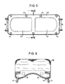
- FIG. 5 schematically shows a mounting frame 40, that for attaching a gas bag 50 to the housing 10 is provided.
- the mounting frame 40 has a general rectangular in shape, and it is along along its longitudinal centerline provided two through openings 42.
- mounting bolts 44 and 46 are provided, some of which, namely the fastening bolts 44, are vertical 5, while others, namely the Bolt 46, extend in the drawing plane of this figure.
- the Fastening frame 40 is together with the fastening bolts 44 or 46 inserted into the interior of the gas bag 50 that the Fastening bolts through openings in the gas bag extend into a blowing opening of the gas bag 50 surrounding fastening section are formed. In this way the mounting frame 40 becomes accurate relative to the gas bag 50 fixed.
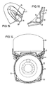
- the gas bag 50 is then over the mounting frame 40 folded so that it has a compact shape and laterally essentially not over the outer edge of the mounting frame 40 stands out. In this folded state the gas bag 50 is fixed so that it is in the further Handling the existing from him and the mounting frame 40 Assembly cannot unfold again.
- a cross section through one folded gas bag 50 and the associated mounting frame 40 is shown in FIG. 6.
- FIGS 7 and 8 are two variants for fixing the Gas bags shown in the collapsed form.
- the gas bag 50 has a rectangular Fixing part 54, one long side of which is fixed to the gas bag 50 connected is; it is preferably sewn to the gas bag 50.
- the other long side of the fixing part 54 is provided with tabs 56, in which openings 58 are formed.
- the one between the two Middle section of the fixing part 54 lying on the longitudinal side is included a line of perforations 60. If the gas bag in the desired, compact shape is folded, it will Fixing part struck over the gas bag, and the openings 58 of the Tabs 56 are hooked into the fastening bolts 44, so that the Airbag 50 is fixed.
- the airbag 50 of a band 65 known to the person skilled in the art in the folded kept compact condition can be made from one Plastic material or another suitable material, for example textile fabrics.
- FIGS. 9 to 11 shown according to the first embodiment after that consisting of the housing 10 and the compressed gas bottle 12 Assembly with the gas bag 50 and the fastening frame 40 existing assembly is assembled.
- the mounting frame 40 is placed together with the gas bag 50 on the housing 10 that the fastening bolts 44 through the openings 18 extend, which are formed in the fastening strip 14.
- On the free ends of the fastening bolts 44 are each a nut screwed.
- the one facing the bottom of the compressed gas container 12 The end face of the receiving part 11 is by means of a base plate 70 closed, which is provided with openings through which the Extension bolts 46 extend through.
- a nut is screwed on, preferably from the same Type like the nuts that are on the mounting bolts 44 are screwed on.
- Pressed retaining nuts are used in the outside Fastening screws are screwed in.
- the holding plate 72 is provided with a holding section that matches the shape of the head is adjusted. Furthermore, the holding section has an opening in which engages an approach of the head of the compressed gas bottle 12. This is can be seen in particular in FIG. 10.
- the bottom plate 70 and the Holding plate 72 are each with a flange 74 with holes 76 provided that for mounting the gas bag restraint module in one Vehicle is provided.
- the design of the gas bag restraint system results in various advantages with regard to the manufacture and assembly of the individual components.
- the housing 10 is preferably based on an extruded profile. This results in a particularly simple manufacture, since apart from the formation of the Bores 18 in the fastening strips 14 and the appropriate length Cutting the extruded profile does not require any processing steps are necessary.
- By the press fit between the receiving part 11 and the compressed gas bottle 12 is in a particularly simple manner in the Housing 10 held. Although actually no additional funds to determine the compressed gas bottle 12 are necessary by the Base plate 70 and the holding plate 72 the security of the down the compressed gas bottle 12 increased.
- the base plate 70 also serves and the holding plate 72 when the housing 10 is not externally sealed is provided as seals for the housing 10 so that a closed space is formed, in which the compressed gas Compressed gas source 12 can flow out.
- the in the mounting frame 40th attached mounting bolts 44 and 46 serve in addition to the Attachment of the mounting frame 40 to the housing 10 and Attachment of the bottom plate 70 and the holding plate 72 also the Fixing the gas bag 50.
- FIGS. 12 to 19 schematically show a second one Embodiment of a gas bag restraint module shown.
- This differs from the first embodiment essentially only characterized in that the receiving part 11 is a trough-like gas bag and has the shape open at the end, that is, the through opening 16 extends along the entire length of the housing 10.
- the same Reference numerals used and in the description of these Components is referred to the explanations for Figures 1 to 11 taken.
- the receiving part 11 Housing elastic, so that the two legs to which the Connect mounting strips 14, movable relative to each other are.
- the dimensions of the compressed gas bottle 12 and the receiving part 11 are adapted to each other so that the compressed gas bottle easily in the Receiving part 11 can be inserted when the fastening strips from the starting position shown in dashed lines in FIG. 12 be separated from each other.
- the attachment strips 14 After the compressed gas bottle 12 in the Mounting part 11 is introduced, the attachment strips 14 released again, and they look due to the elasticity of the Material of the housing 10 to return to the starting position. This is shown in Fig. 12 by the arrows.
- the Outside diameter of the compressed gas bottle 12 is larger than that Inner diameter of the receiving part 11 selected in the starting position, see above that the compressed gas bottle 12 in the receiving part 11 due to the resulting bias is set. Now is the first assembly completely.
- the second assembly the design of which does not differ from the design described above to which first assembly be put on.
- the attachment of the two Assemblies together differ from the explanations above only in that due to the dimensions of the two assemblies relative to each other when screwing the second assembly to the first assembly a clamping force is generated, which the two Fixing strip 14 continues to approach the starting position. This exerts a tensioning effect on the compressed gas cylinder, which is symbolized by the three arrows in FIG. 13.
- the second Assembly works together with the first assembly like one Pipe clamp, inside which the compressed gas bottle 12 is clamped. Due to the polygonal cross-section of the receiving part 11 and The shape of the mounting frame 40 does not exert any direct pressure on it the compressed gas source.
- Receiving part 11 also selected such a polygonal profile be that the mounting frame 40 touches the compressed gas source 12 and sets this together with the receiving part 11, or a circular profile, so that between the receiving part 11 and the mounting frame 40 on one side and the pressurized gas source 12 on the other hand results in a flat clamping effect.
- the first variant of the housing 10 of FIG Airbag restraint module according to the second embodiment is included four screw eyes 80, which are integral with the housing 10 the outside of which are formed. This is particularly advantageous when the housing 10 is made from an extruded profile is.
- screw eyes 80 after mounting the base plate 70 and the holding plate 72 self-tapping screws are screwed in, which together with the fastening bolts 46 the bottom or Set holding plate 70 or 72.
- the one shown in Figure 12 Housing is also provided with three contact surfaces 83 with which the Pressurized gas source is precisely defined and pinched.
- the one in figure 13 shown second variant of the housing 10 is with two Screw eyes 80 provided on the inside of the housing are trained.
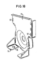
- a gas bag restraint module is shown schematically in FIGS. 14 to 16 according to the second embodiment with a third Variant of the housing 10 shown.
- This housing 10 is outgoing made from a sheet metal part. Because of the better Deformability and machinability of a sheet metal part an extruded profile gives further constructive Possibilities for attaching the bottom plate 70 and Holding plate 72 and for the clamping between the receiving part 11 and the compressed gas source 12.
- the receiving part 11 is in this Variant of the housing 10 provided with abutments 90, their function corresponds to that of the screw eyes 80 of FIG. 13.
- the abutments are each by two circular tabs 92 or 94 formed, seen in the direction of screwing lie one behind the other and relative to each other opposite directions bent out of the material plane are.
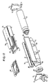
- a gas bag restraint module is shown schematically in FIGS according to the second embodiment with a fourth Variant of the housing 10 shown.
- This variant is also the housing 10 is made from a bent sheet metal part.
- beads 81 are provided, on which the Compressed gas source 12 comes into contact when it is in the housing 10 is clamped.
- Spacer 82 arranged with projections for a clear Angular positioning is provided relative to the receiving part 11 and in same way as the compressed gas source 12 by a clamping action is held. This spacer stabilizes the receiving part 11, improves the definition of the gas bag on the mounting frame 40 and serves as a seal on this side of the compressed gas source 12.
- bending tabs 96 can be used, which the end faces of the receiving part 11 are provided in the Bottom plate 70 or the holding plate 72 formed openings 97th traverse and on the outside of the bottom or holding plate 70 or 72 are bent so that they are fixed.
- Baffle 98 in the area of the head end of the compressed gas source 12 are used. This baffle 98 prevents the Airbag 50 by direct flow from that of the compressed gas source 12 released compressed gas is damaged.
Description
Die Erfindung bezieht sich auf einen Gassack-Rückhaltemodul mit den Merkmalen des Oberbegriffs des Anspruchs 1.The invention relates to an airbag restraint module the features of the preamble of claim 1.
Solche Gassack-Rückhaltemodule sind dem Fachmann auf dem Gebiet der Fahrzeuginsassen-Sicherheitstechnik bekannt. Üblicherweise wird als Aufblasvorrichtung ein sogenannter Gasgenerator mit einer pyrotechnischen Ladung verwendet, die nach Aktivierung in sehr kurzer Zeit ein vorbestimmtes Gasvolumen freisetzt. In jüngster Zeit werden jedoch vermehrt Anstrengungen unternommen, Gassack-Rückhaltemodule zu schaffen, die mit einer deutlich kleineren pyrotechnischen Ladung arbeiten, da deren Verwendung insbesondere hinsichtlich der Umweltverträglichkeit nicht problemlos ist. Durch die Erfindung wird ein Gassack-Rückhaltemodul der eingangs genannten Art bereitgestellt, der an die Verwendung einer Aufblasvorrichtung angepaßt ist, die einen Druckgasbehälter aufweist,insbesondere vom Typ "Heated Gas Inflator". Bei einer solchen Aufblasvorrichtung wird für das Entfalten des Gassacks ein vorbestimmtes Volumen von Gas freigesetzt, das in der Druckgasflasche unter einem hohen Druck eingeschlossen war. Bei der Aktivierung wird in der Aufblasvorrichtung zusätzlich eine chemische Reaktion des in dem Druckgasbehälter enthaltenen Gases eingeleitet, wodurch es zu einer Zunahme der Temperatur des freigesetzten Gases und somit zu einer Zunahme dessen Volumens kommt.Such gas bag restraint modules are known to those skilled in the art the vehicle occupant safety technology known. Usually a so-called gas generator with an pyrotechnic charge used after activation in a very short time Time releases a predetermined gas volume. Most recently however, efforts are increasing to secure gas bag restraint modules create that with a significantly smaller pyrotechnic charge work, since their use in particular with regard to Environmental compatibility is not without problems. Through the invention an airbag restraint module of the type mentioned at the beginning, which is adapted to the use of an inflator, the has a compressed gas container, in particular of the "heated gas" type Inflator ". In such an inflator for the Unfolding the gas bag released a predetermined volume of gas, that trapped in the gas cylinder under a high pressure was. When activated, the inflator will additionally a chemical reaction of the gas contained in the compressed gas container initiated, causing an increase in the temperature of the released gas and thus an increase in its volume.
In der europäischen Offenlegungsschrift EP 0 558 240 A1 ist ein
Gassack-Rückhaltemodul mit einem Gehäuse, einer in diesem
angeordneten Aufblasvorrichtung und einem Gassack beschrieben. Das
Gehäuse weist ein allgemein zylindrisches Aufnahmeteil auf, in das
die Aufblasvorrichtung in axialer Richtung eingeschoben ist, sowie
zwei in axialer Richtung verlaufende, sich ausgehend von dem
Aufnahmeteil nach außen erstreckende Befestigungsstreifen. Das
Aufnahmeteil kann zylindrisch oder wannenförmig ausgebildet sein. Als
Aufblasvorrichtung ist ein zylindrischer pyrotechnischer Gasgenerator
vorgesehen. Die Befestigung des Gassacks an dem Aufnahmeteil kann
durch Einführen eines Befestigungsabschnittes des Gassacks in eine am
Aufnahmeteil vorgesehene Befestigungsrille oder durch Einklemmen des
Befestigungsabschnitts zwischen einem separaten Diffusor und dem
Aufnahmeteil erfolgen. Der zylindrische Gasgenerator ist
konzentrisch, aber im Abstand zu dem Aufnahmeteil angeordnet und wird
entweder mit Hilfe einer stirnseitigen Schraubverbindung in axialer
Richtung in dem Aufnahmeteil verspannt, oder er ist mit umlaufenden
Befestigungsflanschen versehen, die mit Hilfe des auf das
Aufnahmeteil aufgeschraubten Diffusors fixiert werden.In European published
Ein Gassack-Rückhaltemodul nach dem Oberbegriff des Anspruchs 1 ist aus der US 5 263 739 A bekannt.An airbag restraint module according to the preamble of claim 1 known from US 5 263 739 A.
Die nach veröffentliche europäische Offenlegungsschrift EP 0 680 851 A1 beschreibt
ein Gassack-Rückhaltemodul , bei dem ein
flaschenartiger Druckgasbehälter axial in ein Aufnahmeteil
eingespannt ist. Zusätzlich elastische Klammern, in die der
Druckgasbehälter eingeschnappt ist, halten den Gasgenerator in
radialer Richtung an dem Aufnahmeteil.The published European
Mit der Erfindung soll eine einfache und sichere Montage eines Gassack-Rückhaltemoduls erreicht werden.With the invention, a simple and safe installation of a Airbag restraint module can be reached.
Gemäß der Erfindung wird dies bei einem Gassackrückhaltemodul der eingangs genannten Art mit den Merkmalen des kennzeichnenden Teils des Anspruchs 1 erreicht. Durch eine solche Ausgestaltung des Gassack-Rückhaltemoduls sind die Voraussetzungen für eine besonders einfache und sichere Montage des Druckgasbehälters geschaffen.According to the invention, this is the case with a gas bag restraint module initially mentioned type with the characteristics of the characterizing part of claim 1 achieved. By such an embodiment of the Airbag restraint module are the prerequisites for one simple and safe installation of the compressed gas tank created.
Vorzugsweise ist vorgesehen, daß das Gehäuse mit dem Druckgasbehälter einerseits und der Befestigungsrahmen mit dem gefalteten Gassack andererseits zwei vormontierte Baugruppen bilden. Durch die Unterteilung des Gassack-Rückhaltemoduls in zwei Baugruppen, die getrennt vormontierbar sind, ergeben sich weitere Vorteile bei der Montage.It is preferably provided that the housing with the Pressurized gas container on the one hand and the mounting frame with the folded gas bag on the other hand form two pre-assembled modules. By dividing the gas bag restraint module into two Assemblies that can be preassembled separately result in more Assembly advantages.
Vorteilhafte Ausgestaltungen der Erfindung sind in den Unteransprüchen angegeben.Advantageous embodiments of the invention are in the Subclaims specified.
Die Erfindung wird nachfolgend unter Bezugnahme auf zwei Ausführungsformen beschrieben, die in der beigefügten Zeichnung dargestellt sind. In dieser zeigen:
- Fig. 1 eine schematische Draufsicht auf ein Gehäuse mit eingesetztem Druckgasbehälter gemäß einer ersten Ausführungsform des Gassack-Rückhaltemoduls;
- Fig. 2 einen schematischen Querschnitt entlang der Linie II-II von Fig. 1;
- Fig. 3 einen schematischen Querschnitt entlang der Linie III-III von Fig. 1, in dem eine erste Variante des Gehäuses dargestellt ist;
- Fig. 4 einen schematischen Querschnitt entlang der Linie III-III von Fig. 1, in dem eine zweite Variante des Gehäuses dargestellt ist;
- Fig. 5 eine schematische Draufsicht auf den Befestigungsrahmen;
- Fig. 6 einen schematischen Querschnitt durch den mit dem Befestigungsabschnitt versehenen Gassack;
- Fig. 7 eine perspektivische Ansicht eines zusammengefalteten Gassacks gemäß einer ersten Variante;
- Fig. 8 eine perspektivische Ansicht eines zusammengefalteten Gassacks gemäß einer zweiten Variante;
- Fig. 9 eine schematische Draufsicht auf das Gehäuse gemäß der ersten Ausführungsform, in dem der Druckgasbehälter angeordnet und auf dem der Befestigungsrahmen ohne Gassack montiert ist;
- Fig. 10 einen schematischen Längsschnitt durch den montierten Gassack-Rückhaltemodul gemäß der ersten Ausführungsform;
- Fig. 11 einen schematischen Querschnitt durch den montierten Gassack-Rückhaltemodul gemäß der ersten Ausführungsform;
- Fig. 12 einen schematischen Querschnitt durch eine erste Variante des Gehäuses eines Gassack-Rückhaltemoduls gemäß einer zweiten Ausführungsform;
- Fig. 13 einen schematischen Querschnitt durch eine zweite Variante des Gehäuses eines Gassack-Rückhaltemodul gemäß der zweiten Ausführungsform;
- Fig. 14 einen schematischen Querschnitt durch eine dritte Variante des Gehäuses eines Gassack-Rückhaltemodul gemäß der zweiten Ausführungsform;
- Fig. 15 in einer vergrößerten Perspektivansicht ein Detail des Gehäuses von Fig. 14;
- Fig. 16 eine Vorderansicht des Details von Fig. 15;
- Fig. 17 eine Explosionsansicht eines Gassack-Rückhaltemoduls gemäß der zweiten Ausführungsform mit einem Gehäuse gemäß einer vierten Variante;
- Fig. 18 eine perspektivische Ansicht eines Details von Fig. 17; und
- Fig. 19 in einem Längsschnitt ein weiteres Detail des Gehäuses des Gassack-Rückhaltemoduls von Fig. 17.
- Figure 1 is a schematic plan view of a housing with a pressurized gas container according to a first embodiment of the gas bag restraint module.
- Fig. 2 is a schematic cross section along the line II-II of Fig. 1;
- Fig. 3 is a schematic cross section along the line III-III of Figure 1, in which a first variant of the housing is shown.
- Fig. 4 is a schematic cross section along the line III-III of Fig. 1, in which a second variant of the housing is shown;
- Figure 5 is a schematic plan view of the mounting frame.
- 6 shows a schematic cross section through the gas bag provided with the fastening section;
- 7 shows a perspective view of a folded gas bag according to a first variant;
- 8 shows a perspective view of a folded gas bag according to a second variant;
- 9 shows a schematic plan view of the housing according to the first embodiment, in which the compressed gas container is arranged and on which the fastening frame is mounted without an airbag;
- 10 shows a schematic longitudinal section through the assembled gas bag restraint module according to the first embodiment;
- 11 shows a schematic cross section through the assembled gas bag restraint module according to the first embodiment;
- 12 shows a schematic cross section through a first variant of the housing of an airbag restraint module according to a second embodiment;
- 13 shows a schematic cross section through a second variant of the housing of an airbag restraint module according to the second embodiment;
- 14 shows a schematic cross section through a third variant of the housing of an airbag restraint module according to the second embodiment;
- FIG. 15 shows an enlarged perspective view of a detail of the housing from FIG. 14;
- Figure 16 is a front view of the detail of Figure 15;
- 17 shows an exploded view of an airbag restraint module according to the second embodiment with a housing according to a fourth variant;
- Figure 18 is a perspective view of a detail of Figure 17; and
- 19 shows a further detail of the housing of the gas bag restraint module from FIG. 17 in a longitudinal section.
Das Gassack-Rückhaltemodul besteht aus zwei getrennt vormontierbaren Baugruppen, von denen die erste das Gehäuse mit dem Druckgasbehälter und die zweite der Gassack mit seinem Befestigungsrahmen ist.The gas bag restraint module consists of two separately preassembled ones Assemblies, the first of which is the housing with the compressed gas tank and the second the gas bag with its mounting frame is.
In den Figuren 1 bis 11 ist schematisch eine erste Ausführungsform
eines Gehäuse 10 eines Gassack-Rückhaltemoduls dargestellt.
Dieses Gehäuse 10 weist einen allgemein zylindrischen Aufnahmeteil 11
auf, in dem ein Druckgasbehälter 12 in axialer Richtung eingeschoben
ist, sowie zwei in axialer Richtung verlaufende, sich ausgehend von
dem Aufnahmeteil 11 nach außen erstreckende Befestigungsstreifen 14.
Zwischen den Befestigungsstreifen 14 sind in dem Aufnahmeteil 11 zwei
Durchgangsöffnungen 16 ausgebildet. Wie in den Figuren 3 und 4 zu
sehen ist, ist jeder Befestigungsstreifen 14 zweifach abgekantet, so
daß zwischen den in den Figuren 3 und 4 senkrecht nach oben abstehenden
Abschnitten der Befestigungsstreifen 14 ein Aufnahmeraum
ausgebildet ist. In dem an den Aufnahmeteil 11 angrenzenden Abschnitt
der Befestigungsstreifen 14 sind mehrere Befestigungslöcher 18
ausgebildet.A first embodiment is shown schematically in FIGS. 1 to 11
of a
Die Druckgasflasche 12 enthält unter Druck stehendes Gas, das
nach Zündung einer pyrotechnischen Hilfsladung zur Aktivierung des
Gassack-Rückhaltemoduls aus dieser im Bereich des Kopfs ausströmt.
Ferner wird bei der Aktivierung eine chemische Reaktion des
Druckgases eingeleitet, die zu einer Zunahme der Temperatur des
freigesetzten Gases und somit zu einer Zunahme seines Volumens führt.The
Die Druckgasflasche 12 ist in dem Aufnahmeteil 11 mittels
Preßsitz gehalten. Zur Erhaltung dieses Preßsitzes werden zwei
Varianten bevorzugt, von denen die erste in Fig. 3 dargestellt ist.
Gemäß dieser Variante des Gehäuses 10 hat das Aufnahmeteil 11 einen
polygonartigen Querschnitt, so daß der Preßsitz zwischen den
Abschnitten des Aufnahmeteils 11 mit dem geringsten radialen Abstand
von der Mittellängsachse und der Wandung der Druckgasflasche gebildet
ist. Die Berührstellen zwischen dem Aufnahmeteil 11 und der
Druckgasflasche 12 sind durch Pfeile gekennzeichnet.The
In Fig. 4 ist eine zweite Variante der Ausgestaltung des Gehäuses
10 dargestellt. Gemäß diesem Beispiel weist das Aufnahmeteil 11 einen
im wesentlichen kreisförmigen Querschnitt auf, so daß sich eine
Berührung zwischen der Wandung des Aufnahmeteils 11 und der Wandung
der Druckgasflasche 12 entlang einem großen Oberflächenbereich der
Druckgasflasche 12 ergibt. Auch in dieser Figur sind die Bereiche der
Berührung zwischen dem Aufnahmeteil 11 und der Druckgasflasche 12
durch Pfeile gekennzeichnet.4 is a second variant of the design of the
Bei den beiden in den Figuren 3 und 4 gezeigten Varianten des
Aufnahmeteils 11 sind dessen Abmessungen so auf die Abmessungen der
Druckgasflasche 12 abgestimmt, daß die Druckgasflasche 12 für ihre
Montage in dem Aufnahmeteil 11 unter Kraftaufwendung in das Innere
des Aufnahmeteils 11 eingeschoben wird. Dieses Einschieben beginnt
vorzugsweise mit dem kopfseitigen Ende der Druckgasflasche 12, so daß
der sanfte Übergang zwischen dem Kopf der Druckgasflasche und deren
Mantelfläche den Beginn des Einschiebens erleichtert. Die sich bei
der Montage der Druckgasflasche 12 ergebende Preßpassung
gewährleistet einen festen Sitz der Druckgasflasche 12 in dem
Aufnahmeteil 11, ohne daß weitere Mittel zur Festlegung der
Druckgasflasche 12 notwendig sind. Nach dem Einbringen der
Druckgasflasche 12 in das Gehäuse 10 ist die erste Baugruppe
vormontiert.In the two variants of the
Receiving
In Fig. 5 ist schematisch ein Befestigungsrahmen 40 dargestellt,
der für die Befestigung eines Gassacks 50 an dem Gehäuse 10
vorgesehen ist. Der Befestigungsrahmen 40 weist eine allgemein
rechteckige Form auf, und er ist entlang seiner Längsmittellinie mit
zwei Durchgangsöffnungen 42 versehen. Entlang dem Umfangsrand des
Befestigungsrahmens 40 sind Befestigungsbolzen 44 bzw. 46 vorgesehen,
von denen sich einige, nämlich die Befestigungsbolzen 44, senkrecht
zur Zeichenebene von Fig. 5 erstrecken, während andere, nämlich die
Bolzen 46, sich in der Zeichenebene dieser Figur erstrecken. Der
Befestigungsrahmen 40 wird zusammen mit den Bcfestigungsbolzen 44
bzw. 46 so in das Innere des Gassacks 50 eingelegt, daß sich die
Befestigungsbolzen durch Öffnungen in dem Gassack hindurch
erstrecken, die in einem eine Einblasöffnung des Gassacks 50
umgebenden Befestigungsabschnitt ausgebildet sind. Auf diese Weise
wird der Befestigungsrahmen 40 relativ zu dem Gassack 50 genau
fixiert. Anschließend wird der Gassack 50 über dem Befestigungsrahmen
40 so zusammengefaltet, daß er eine kompakte Gestalt aufweist und
seitlich im wesentlichen nicht über den Außenrand des Befestigungsrahmens
40 hinaussteht. In diesem zusammengefalteten Zustand
wird der Gassack 50 fixiert, so daß er sich bei der weiteren
Handhabung der aus ihm und dem Befestigungsrahmen 40 bestehenden
Baugruppe nicht wieder entfalten kann. Ein Querschnitt durch einen
zusammengefalteten Gassack 50 und den dazugehörigen Befestigungsrahmen
40 ist in Fig. 6 dargestellt.5 schematically shows a mounting
In den Figuren 7 und 8 sind zwei Varianten für das Fixieren des
Gassacks in der zusammengelegten Form dargestellt. Bei der in Fig. 7
dargestellten Variante weist der Gassack 50 ein rechteckiges
Fixierungsteil 54 auf, dessen eine Längsseite fest mit dem Gassack 50
verbunden ist; vorzugsweise ist es mit dem Gassack 50 vernäht. Die
andere Längsseite des Fixierungsteils 54 ist mit Laschen 56 versehen,
in denen Öffnungen 58 ausgebildet sind. Der zwischen den beiden
Längsseiten liegende Mittelabschnitt des Fixierungsteils 54 ist mit
einer Perforationslinie 60 versehen. Wenn der Gassack in die
gewünschte, kompakte Gestalt zusammengefaltet ist, wird das
Fixierungsteil über den Gassack geschlagen, und die Öffnungen 58 der
Laschen 56 werden in die Befestigungsbolzen 44 eingehängt, so daß der
Gassack 50 fixiert ist. Durch die Perforation 60 ist eine
Aufreißlinie vorgegeben, entlang der das Fixierungsteil 54 bei einer
Aktivierung des Gassack-Rückhaltemoduls aufreißt und den Gassack
freigibt. Wenn der Gassack 50 auf diese Weise fixiert ist, kann die
aus dem Gassack und dem Befestigungsrahmen 40 bestehende Baugruppe
problemlos gehandhabt werden, insbesondere für die Montage an dem
vormontierten Gehäuse 10.In Figures 7 and 8 are two variants for fixing the
Gas bags shown in the collapsed form. In the case of FIG. 7
shown variant, the
Bei der in Fig. 8 dargestellten Variante wird der Gassack 50 von
einer dem Fachmann bekannten Banderole 65 in dem zusammengefalteten,
kompakten Zustand gehalten. Diese Banderole 65 kann aus einem
Kunststoffmaterial oder einem anderen geeigneten Material bestehen,
beispielsweise Textilgewebe.In the variant shown in FIG. 8, the
In den Figuren 9 bis 11 ist schließlich das Gassack-Rückhaltemodul
gemäß der ersten Ausführungsform dargestellt, nachdem
die aus dem Gehäuse 10 und der Druckgasflasche 12 bestehende
Baugruppe mit der aus dem Gassack 50 und dem Befestigungsrahmen 40
bestehenden Baugruppe zusammengefügt ist. Der Befestigungsrahmen 40
ist zusammen mit dem Gassack 50 so auf das Gehäuse 10 aufgesetzt, daß
sich die Befestigungsbolzen 44 durch die Öffnungen 18 hindurch
erstrecken, die in den Befestigungsstreifen 14 ausgebildet sind. Auf
die freien Enden der Befestigungsbolzen 44 ist jeweils eine Mutter
aufgeschraubt. Die dem Boden des Druckgasbehälters 12 zugewandte
Stirnseite des Aufnahmeteils 11 ist mittels einer Bodenplatte 70
verschlossen, die mit Öffnungen versehen ist, durch die sich die
Befestigungsbolzen 46 hindurch erstrecken. Die dem Kopf des
Druckgasbehälters 12 zugewandte Stirnseite des Aufnahmeteils 11 ist
mittels einer Halteplatte 72 verschlossen, die ebenfalls mit
Öffnungen versehen ist, durch die sich die Befestigungsbolzen 46
hindurch erstrecken. Auf die freien Enden der Befestigungsbolzen 46
ist jeweils eine Mutter aufgeschraubt, die vorzugsweise von demselben
Typ wie die Muttern sind, die auf die Befestigungsbolzen 44
aufgeschraubt sind. Alternativ können in den Befestigungsrahmen
eingepreßte Haltemuttern verwendet werden, in die von außen
Befestigungsschrauben eingeschraubt werden. Die Halteplatte 72 ist
mit einem Halteabschnitt versehen, der an die Gestalt des Kopfs
angepaßt ist. Ferner weist der Halteabschnitt eine Öffnung auf, in
die ein Ansatz des Kopfs der Druckgasflasche 12 eingreift. Dies ist
insbesondere in Fig. 10 zu sehen. Die Bodenplatte 70 und die
Halteplatte 72 sind jeweils mit einem Flansch 74 mit Bohrungen 76
versehen, der für eine Montage des Gassack-Rückhaltemoduls in einem
Fahrzeug vorgesehen ist.Finally, the gas bag restraint module is shown in FIGS. 9 to 11
shown according to the first embodiment after
that consisting of the
Durch die Gestaltung des Gassack-Rückhaltesystems ergeben sich
verschiedene Vorteile hinsichtlich der Fertigung und der Montage der
einzelnen Bauteile. Das Gehäuse 10 ist vorzugsweise ausgehend von
einem Strangpreßprofil hergestellt. Dadurch ergibt sich eine
besonders einfache Herstellung, da abgesehen von dem Ausbilden der
Bohrungen 18 in den Befestigungsstreifen 14 und dem längengerechten
Abschneiden des Strangpreßprofils keinerlei Bearbeitungsschritte
notwendig sind. Durch den Preßsitz zwischen dem Aufnahmeteil 11 und
der Druckgasflasche 12 wird diese in besonders einfacher Weise in dem
Gehäuse 10 gehalten. Obwohl eigentlich keinerlei zusätzliche Mittel
zur Festlegung der Druckgasflasche 12 notwendig sind, wird durch die
Bodenplatte 70 und die Halteplatte 72 die Sicherheit der Festlegung
der Druckgasflasche 12 gesteigert. Ferner dienen die Bodenplatte 70
und die Halteplatte 72, wenn keine externe Abdichtung des Gehäuses 10
vorgesehen ist, als Dichtungen für das Gehäuse 10, so daß ein
abgeschlossener Raum gebildet ist, in den das Druckgas der
Druckgasquelle 12 ausströmen kann. Die in dem Befestigungsrahmen 40
angebrachten Befestigungsbolzen 44 bzw. 46 dienen neben der
Befestigung des Befestigungsrahmens 40 am Gehäuse 10 und der
Befestigung der Bodenplatte 70 bzw. der Halteplatte 72 auch der
Fixierung des Gassacks 50. Schließlich ist das erfindungsgemäße
Gassack-Rückhaltemodul in zwei voneinander getrennten Baugruppen
vormontierbar, die in besonders einfacher Weise handhabbar sind, ohne
daß zusätzliche Sicherungen während der Handhabung notwendig sind.The design of the gas bag restraint system results in
various advantages with regard to the manufacture and assembly of the
individual components. The
In den Figuren 12 bis 19 ist schematisch eine zweite
Ausführungsform eines Gassack-Rückhaltemoduls dargestellt. Dieses
unterscheidet sich von der ersten Ausführungsform im wesentlichen nur
dadurch, daß der Aufnahmeteil 11 eine wannenartige, zum Gassack und
stirnseitig geöffnete Gestalt hat, sich die Durchgangsöffnung 16 also
entlang der gesamten Länge des Gehäuses 10 erstreckt. Soweit Bauelemente
des Gassack-Rückhaltemoduls gemäß der zweiten Ausführungsform
Bauelementen entsprechen, die von dem Gassack-Rückhaltemodul gemäß
der ersten Ausführungsform bekannt sind, werden dieselben
Bezugszeichen verwendet, und hinsichtlich der Beschreibung dieser
Bauelemente wird auf die Erläuterungen zu den Figuren 1 bis 11 Bezug
genommen.FIGS. 12 to 19 schematically show a second one
Embodiment of a gas bag restraint module shown. This
differs from the first embodiment essentially only
characterized in that the receiving
Aufgrung der wannenartigen Gestalt des Aufnahmeteils 11 ist das
Gehäuse elastisch, so daß die beiden Schenkel, an die sich die
Befestigungsstreifen 14 anschließen, relativ zueinander bewegbar
sind. Die Abmessungen der Druckgasflasche 12 und des Aufnahmeteils 11
sind so aneinander angepaßt, daß die Druckgasflasche leicht in den
Aufnahmeteil 11 eingeschoben werden kann, wenn die Befestigungsstreifen
aus der in Fig. 12 gestrichelt dargestellten Ausgangslage
voneinander entfernt werden. Nachdem die Druckgasflasche 12 in den
Aufnahmeteil 11 eingebracht ist, werden die Befesligungsstreifen 14
wieder freigegeben, und sie suchen aufgrund der Elastizität des
Materials des Gehäuses 10, wieder in die Ausgangslage zurückzukehren.
Dies ist in Fig. 12 durch die Pfeile dargestellt. Der
Außendurchmesser der Druckgasflasche 12 ist größer als der
Innendurchmesser des Aufnahmeteils 11 in der Ausgangslage gewählt, so
daß die Druckgasflasche 12 in dem Aufnahmeteil 11 aufgrund der sich
ergebenden Vorspannung festgelegt ist. Nun ist die erste Baugruppe
komplett.This is due to the trough-like shape of the receiving
Anschließend kann die zweite Baugruppe, deren Gestaltung sich
nicht von der oben beschriebenen Gestaltung unterscheidet, auf die
erste Baugruppe aufgesetzt werden. Die Befestigung der beiden
Baugruppen aneinander unterscheidet sich von den obigen Erläuterungen
nur dadurch, daß aufgrund der Abmessungen der beiden Baugruppen
relativ zueinander beim Verschrauben der zweiten Baugruppe an der
ersten Baugruppe eine Spannkraft erzeugt wird, welche die beiden
Befestigungsstreifen 14 weiter der Ausgangslage anzunähern sucht.
Dadurch wird auf die Druckgasflasche eine Spannwirkung ausgeübt,
welche durch die drei Pfeile in Fig. 13 symbolisiert ist. Die zweite
Baugruppe wirkt mit der ersten Baugruppe zusammen wie eine
Rohrschelle, in deren Inneren die Druckgasflasche 12 eingespannt ist.
Aufgrund des polygonartigen Querschnitts des Aufnahmeteils 11 und der
Form des Befestigungsrahmens 40 übt dieser keinen direkten Druck auf
die Druckgasquelle aus. Je nach Art der gewünschten Klemmung zwischen
dem Aufnahmeteil 11 und der Druckgasquelle 12 kann für das
Aufnahmeteil 11 auch ein solches polygonartiges Profil gewählt
werden, daß der Befestigungsrahmen 40 die Druckgasquelle 12 berührt
und diese zusammen mit dem Aufnahmeteil 11 festlegt, oder ein
kreisförmiges Profil, so daß sich zwischen dem Aufnahmeteil 11 und
dem Befestigungsrahmen 40 auf der einen Seite und der Druckgasquelle
12 auf der anderen Seite eine flächige Klemmwirkung ergibt. Then the second assembly, the design of which
does not differ from the design described above to which
first assembly be put on. The attachment of the two
Assemblies together differ from the explanations above
only in that due to the dimensions of the two assemblies
relative to each other when screwing the second assembly to the
first assembly a clamping force is generated, which the two
Die in Figur 12 dargestellte erste Variante des Gehäuses 10 des
Gassack-Rückhaltemoduls gemäß der zweiten Ausführungsform ist mit
vier Schraubaugen 80 versehen, die einstückig mit dem Gehäuse 10 auf
dessen Außenseite ausgebildet sind. Dies ist besonders vorteilhaft,
wenn das Gehäuse 10 ausgehend von einem Strangpreßprofil hergestellt
ist. In diese Schraubaugen 80 werden nach der Montage der Bodenplatte
70 und der Halteplatte 72 selbstschneidende Schrauben eingeschraubt,
welche zusammen mit den Befestigungsbolzen 46 die Boden- bzw. die
Halteplatte 70 bzw. 72 festlegen. Das in Figur 12 dargestellte
Gehäuse ist ferner mit drei Anlageflächen 83 versehen, mit denen die
Druckgasquelle präzise festgelegt und eingeklemmt wird. Die in Figur
13 dargestellte zweite Variante des Gehäuses 10 ist mit zwei
Schraubaugen 80 versehen, die auf der Innenseite des Gehäuses
ausgebildet sind.The first variant of the
In den Figuren 14 bis 16 ist schematisch ein Gassack-Rückhaltemodul
gemäß der zweiten Ausführungsform mit einer dritten
Variante des Gehäuses 10 dargestellt. Dieses Gehäuse 10 ist ausgehend
von einem Blechbiegeteil hergestellt. Aufgrund der besseren
Verformbarkeit und Bearbeitbarkeit eines Blechbiegeteils gegenüber
einem Strangpreßprofil ergeben sich weitere konstruktive
Möglichkeiten für die Befestigung der Bodenplatte 70 und der
Halteplatte 72 sowie für die Klemmung zwischen dem Aufnahmeteil 11
und der Druckgasquelle 12. Der Aufnahmeteil 11 ist bei dieser
Variante des Gehäuses 10 mit Widerlagern 90 versehen, deren Funktion
derjenigen der Schraubaugen 80 von Fig. 13 entspricht. Die Widerlager
sind jeweils durch zwei kreisabschnittsförmige Materiallaschen 92
bzw. 94 gebildet, die in der Verschraubungsrichtung gesehen
hintereinander liegen und relativ zu dieser in zueinander
entgegengesetzten Richtungen aus der Materialebene herausgebogen
sind.A gas bag restraint module is shown schematically in FIGS. 14 to 16
according to the second embodiment with a third
Variant of the
In den Figuren 17 bis 19 ist schematisch ein Gassack-Rückhaltemodul
gemäß der zweiten Ausführungsform mit einer vierten
Variante des Gehäuses 10 dargestellt. Auch bei dieser Variante ist
das Gehäuse 10 ausgehend von einem Blechbiegeteil hergestellt. An dem
Aufnahmeteil 11 sind Sicken 81 vorgesehen, an denen die
Druckgasquelle 12 in Anlage gelangt, wenn sie in dem Gehäuse 10
eingespannt ist. Für die Positionierung der Druckgasquelle relativ
zum Gehäuse ist an dem kopfseitigen Ende der Druckgasquelle 12 eine
Distanzscheibe 82 angeordnet, die mit Vorsprüngen für eine eindeutige
Winkelpositionierung relativ zum Aufnahmeteil 11 versehen ist und in
gleicher Weise wie die Druckgasquelle 12 durch eine Klemmwirkung
gehalten wird. Diese Distanzscheibe stabilisiert den Aufnahmeteil 11,
verbessert die Festlegung des Gassacks am Befestigungsrahmen 40 und
dient als Dichtung auf dieser Seite der Druckgasquelle 12.A gas bag restraint module is shown schematically in FIGS
according to the second embodiment with a fourth
Variant of the
Anstelle von Schrauben zur Befestigung der Bodenplatte 70 bzw.
der Halteplatte 72 können Biegelaschen 96 verwendet werden, die an
den Stirnseiten des Aufnahmeteils 11 vorgesehen sind, in der
Bodenplatte 70 bzw. der Halteplatte 72 gebildete Öffnungen 97
durchqueren und auf der Außenseite der Boden- bzw. der Halteplatte 70
bzw. 72 umgebogen sind, so daß diese festgelegt sind.Instead of screws for fastening the
Bei der Montage der zweiten Baugruppe an der ersten Baugruppe
kann zwischen dem Befestigungsrahmen 40 und dem Aufnahmeteil 11 ein
Ablenkblech 98 im Bereich des kopfseitigen Endes der Druckgasquelle
12 eingesetzt werden. Dieses Ablenkblech 98 verhindert, daß der
Gassack 50 durch direkte Anströmung von dem von der Druckgasquelle 12
freigesetzten Druckgas beschädigt wird.When mounting the second module on the first module
can between the mounting
Claims (21)
- A gas bag restraint module comprising a housing (10), an inflator (12) located in the housing and providing a volume of pressurized gas after activation, and a folded gas bag (50) which has an attachment section fixed to the housing (10) and surrounding an inflation aperture, the housing (10) having a generally trough-like accommodation part (11), which is open towards the gas bas and on its end faces and into which the inflator (12) is axially inserted, as well as two attachment strips (14) which extend in the axial direction outwards starting from the accommodation part (11), the attachment section of the gas bag (50) being provided with an attachment frame (40) and the attachment frame (40) being accommodated between the attachment strips (14), characterized in that the inflator has a bottle-type pressurized gas container (12) and the pressurized gas container (12) and the accommodation part (11) are dimensioned such that the pressurized gas container (12) is held in the accommodation part (11) with a press fit, the pressurized gas container (12) being clamped in place by the wall of the accommodation part (11), which is open on its end faces.
- The gas bag restraint module according to claim 1, characterized in that the generally trough-shaped accommodation part (11) has a circular cross-section.
- The gas bag restraint module according to claim 1, characterized in that the generally trough-shaped accommodation part (11) has a polygonal cross-section.
- The gas bag restraint module according to any of the preceding claims, characterized in that the pressurized gas container (12) has a circular cross-section.
- The gas bag restraint module according to claim 1, characterized in that the accommodation part (11) and the attachment frame (40) cooperate with the pressurized gas container (12) in the nature of a pipe clamp, so that a clamping effect is produced by which the pressurized gas container (12) is firmly held in the accommodation part (11).
- The gas bag restraint module according to any of the preceding claims, characterized in that the housing (10) together with the pressurized gas container (12), on the one hand, and the attachment frame (40) together with the folded gas bag (50), on the other, form two preassembled units.
- The gas bag restraint module according to any of the preceding claims, characterized in that the end face of the accommodation part (11) facing the base of the pressurized gas container (12) is closed by means of a base plate (70).
- The gas bag restraint module according to any of the preceding claims, characterized in that the end face of the accommodation part (11) facing the head of the pressurized gas container (12) is closed by means of a retaining plate (72), which is provided with a retaining section adapted in shape to the head of the pressurized gas cylinder (12).
- The gas bag restraint module according to either one of claims 7 and 8, characterized in that the base plate (70) and, respectively, the retaining plate (72) closing the end faces of the accommodation part (11) are bolted to the accommodation part (11).
- The gas bag restraint module according to any of claims 7 to 9, characterized in that the base plate (70) and, respectively, the retaining plate (72) are provided with a flange (74) for fitting the gas bag restraint module.
- The gas bag restraint module according to any of the preceding claims, characterized in that the housing (10) is manufactured from an extruded section.
- The gas bag restraint module according to claim 11, characterized in that at least one bolt hole (80) for a self-tapping bolt is integrally formed with the accommodation part (11).
- The gas bag restraint module according to any of claims 1 to 10, characterized in that the housing (10) is manufactured from a bent sheet metal part.
- The gas bag restraint module according to claim 13, characterized in that the accommodation part (11) is provided with beads (81) projecting into its interior.
- The gas bag restraint module according to claim 9 and claim 13, characterized in that the accommodation part (11) is provided with at least one buttress (90) for a self-tapping bolt, the buttress being formed from two tabs of material (92, 94) in the shape of segments of a circle and which are located one behind the other as viewed in the longitudinal direction of the bolt and, in relation to the longitudinal direction of the bolt, are bent out of the plane of the material in opposite directions to each other.
- The gas bag restraint module according to either one of claims 7 and 8 and according to claim 14, characterized in that the accommodation part (11) is provided on its end faces with bent tabs (96) which pass through openings (97) formed in the base plate (70) and, respectively, the retaining plate (72) and are bent over on the outside of the base plate (70) and, respectively, the retaining plate (72).
- The gas bag restraint module according to either one of claims 7 and 8, characterized in that the attachment frame (40) is provided with attachment bolts (46) which pass through openings formed in the base plate (70) and, respectively, the retaining plate (72).
- The gas bag restraint module according to any of the preceding claims, characterized in that the attachment frame (40) is provided with attachment bolts (44) which pass through openings formed in the attachment section of the gas bag (50).
- The gas bag restraint module according to claim 18, characterized in that the gas bag (50) has a substantially rectangular locating part (54), one long side of which is firmly connected to the gas bag (50) in the region of the attachment section, the middle section of which, adjoining this first long side, is passed over the folded gas bag (50), and the second long side of which, adjoining the middle section and opposite the first long side, is fixed to the attachment frame (40) by means of tabs (56) which are arranged along the second long side and have openings (58) into which a part of the attachment bolts (44) engages, the middle section being provided with a perforated line (60) which is torn open by the gas bag (50) when it unfolds.
- The gas bag restraint module according to any of the preceding claims, characterized in that a deflection plate (98) is arranged between the attachment frame (40) and the accommodation part (11) on the side facing the head of the pressurized gas container (12).
- The gas bag restraint module according to claim 8, characterized in that a spacer washer (82) is arranged between the retaining plate (72) and the pressurized gas source (12), the spacer washer being provided with protrusions for unequivocal angular positioning in relation to the accommodation part (11).
Applications Claiming Priority (5)
| Application Number | Priority Date | Filing Date | Title |
|---|---|---|---|
| DE19532768A DE19532768A1 (en) | 1995-09-05 | 1995-09-05 | Gas bag retainer module |
| DE19532768 | 1995-09-05 | ||
| DE29604345U | 1996-03-08 | ||
| DE29604345U DE29604345U1 (en) | 1995-09-05 | 1996-03-08 | Airbag restraint module |
| EP96112727A EP0761506B1 (en) | 1995-09-05 | 1996-08-07 | Air bag restraint module |
Related Parent Applications (2)
| Application Number | Title | Priority Date | Filing Date |
|---|---|---|---|
| EP96112727.1 Division | 1996-08-07 | ||
| EP96112727A Division EP0761506B1 (en) | 1995-09-05 | 1996-08-07 | Air bag restraint module |
Publications (3)
| Publication Number | Publication Date |
|---|---|
| EP1022196A2 EP1022196A2 (en) | 2000-07-26 |
| EP1022196A3 EP1022196A3 (en) | 2000-10-11 |
| EP1022196B1 true EP1022196B1 (en) | 2003-06-18 |
Family
ID=7771327
Family Applications (1)
| Application Number | Title | Priority Date | Filing Date |
|---|---|---|---|
| EP00110212A Expired - Lifetime EP1022196B1 (en) | 1995-09-05 | 1996-08-07 | Air bag restraint module |
Country Status (4)
| Country | Link |
|---|---|
| EP (1) | EP1022196B1 (en) |
| KR (1) | KR100223117B1 (en) |
| DE (4) | DE19532768A1 (en) |
| TW (1) | TW336198B (en) |
Families Citing this family (7)
| Publication number | Priority date | Publication date | Assignee | Title |
|---|---|---|---|---|
| EP0794091B1 (en) * | 1996-03-08 | 2001-05-16 | TRW Occupant Restraint Systems GmbH & Co. KG | Air bag restraint module |
| DE29612777U1 (en) * | 1996-07-23 | 1996-11-21 | Trw Repa Gmbh | Airbag module for a vehicle occupant restraint system |
| DE29701063U1 (en) * | 1997-01-22 | 1997-05-22 | Trw Repa Gmbh | Airbag module |
| DE19928696B4 (en) * | 1999-06-23 | 2005-06-16 | Autoliv Development Ab | Airbag arrangement with a container having bending surfaces |
| DE20112313U1 (en) | 2001-07-26 | 2001-11-29 | Trw Repa Gmbh | Assembly of a cylindrical gas generator, housing and holding part |
| DE102004007415B4 (en) * | 2004-02-16 | 2006-02-09 | Key Safety Systems, Inc.(n.d.Ges.d.Staates Delaware), Sterling Heights | Attachment for a gas bag |
| DE202006006903U1 (en) * | 2006-04-26 | 2007-09-06 | Autoliv Development Ab | Banderole and airbag unit with banderole |
Family Cites Families (5)
| Publication number | Priority date | Publication date | Assignee | Title |
|---|---|---|---|---|
| US5058919A (en) * | 1990-06-15 | 1991-10-22 | Trw Vehicle Safety Systems, Inc | Air bag module construction and assembly technique |
| US5332256A (en) * | 1992-02-24 | 1994-07-26 | Morton International, Inc. | Continuous circumference diffuser reaction canister |
| US5263739A (en) * | 1992-12-28 | 1993-11-23 | General Motors Corporation | Air bag module |
| ES2141798T3 (en) * | 1993-04-12 | 2000-04-01 | Autoliv Asp Inc | REACTION BOX FOR AN INFLATABLE RETENTION SYSTEM WITH INTEGRATED INFLATOR CHAMBER. |
| WO1994025313A1 (en) * | 1993-04-30 | 1994-11-10 | Alliedsignal Inc. | Air bag module with extruded housing |
-
1995
- 1995-09-05 DE DE19532768A patent/DE19532768A1/en not_active Withdrawn
-
1996
- 1996-03-08 DE DE29604345U patent/DE29604345U1/en not_active Expired - Lifetime
- 1996-08-07 DE DE59610546T patent/DE59610546D1/en not_active Expired - Fee Related
- 1996-08-07 EP EP00110212A patent/EP1022196B1/en not_active Expired - Lifetime
- 1996-08-07 DE DE59607992T patent/DE59607992D1/en not_active Expired - Lifetime
- 1996-08-29 KR KR1019960036267A patent/KR100223117B1/en not_active IP Right Cessation
-
1997
- 1997-03-03 TW TW086102698A patent/TW336198B/en active
Also Published As
| Publication number | Publication date |
|---|---|
| DE59610546D1 (en) | 2003-07-24 |
| TW336198B (en) | 1998-07-11 |
| KR970015273A (en) | 1997-04-28 |
| KR100223117B1 (en) | 1999-10-15 |
| EP1022196A2 (en) | 2000-07-26 |
| DE19532768A1 (en) | 1997-03-06 |
| DE29604345U1 (en) | 1996-07-18 |
| DE59607992D1 (en) | 2001-11-29 |
| EP1022196A3 (en) | 2000-10-11 |
Similar Documents
| Publication | Publication Date | Title |
|---|---|---|
| EP0761506B1 (en) | Air bag restraint module | |
| EP1108626B1 (en) | Airbag restraint module | |
| DE10224726B4 (en) | Airbag retaining clip | |
| WO2009056598A1 (en) | Airbag module | |
| DE4309925C2 (en) | Airbag unit | |
| WO1999019173A1 (en) | Inflatable protection device for protecting head and chest areas of passengers in an automobile during a side collision | |
| DE4310173C2 (en) | Airbag module | |
| WO2016142083A1 (en) | Airbag module and vehicle | |
| EP2134575B1 (en) | Airbag arrangement for a vehicle occupant restraint system | |
| EP0792773A1 (en) | Airbag module housing assembly with a multiplicity of separable components | |
| EP0857626A2 (en) | Gas generator and pipe assembly for a vehicle occupant restraint system | |
| EP1022196B1 (en) | Air bag restraint module | |
| EP0794091B1 (en) | Air bag restraint module | |
| EP0802088A2 (en) | Vehicle airbag module | |
| DE19621397B4 (en) | airbag module | |
| DE19508533A1 (en) | Airbag device and method for removing an inflator from the airbag device | |
| DE10216217A1 (en) | airbag unit | |
| EP1533198A1 (en) | Airbag module | |
| DE19710063B4 (en) | Airbag with gas generator | |
| EP1034988B1 (en) | Attachment for the dash panel of a passenger car equipped with an airbag | |
| EP0822124A1 (en) | Airbag module for a vehicle passenger restraining system | |
| DE4335831A1 (en) | Structure for mounting an inflator in an air bag device | |
| EP1060957B1 (en) | Airbag module unit, and airbag module | |
| EP1088711A2 (en) | Passenger side air bag module for a motor vehicle | |
| EP2236361B1 (en) | Airbag component assembly |
Legal Events
| Date | Code | Title | Description |
|---|---|---|---|
| PUAI | Public reference made under article 153(3) epc to a published international application that has entered the european phase |
Free format text: ORIGINAL CODE: 0009012 |
|
| AC | Divisional application: reference to earlier application |
Ref document number: 761506 Country of ref document: EP |
|
| AK | Designated contracting states |
Kind code of ref document: A2 Designated state(s): DE ES FR GB IT SE |
|
| RIN1 | Information on inventor provided before grant (corrected) |
Inventor name: LUTZ, JOACHIM |
|
| PUAL | Search report despatched |
Free format text: ORIGINAL CODE: 0009013 |
|
| AK | Designated contracting states |
Kind code of ref document: A3 Designated state(s): DE ES FR GB IT SE |
|
| 17P | Request for examination filed |
Effective date: 20010102 |
|
| AKX | Designation fees paid |
Free format text: DE ES FR GB IT SE |
|
| 17Q | First examination report despatched |
Effective date: 20020503 |
|
| GRAH | Despatch of communication of intention to grant a patent |
Free format text: ORIGINAL CODE: EPIDOS IGRA |
|
| GRAH | Despatch of communication of intention to grant a patent |
Free format text: ORIGINAL CODE: EPIDOS IGRA |
|
| GRAA | (expected) grant |
Free format text: ORIGINAL CODE: 0009210 |
|
| AC | Divisional application: reference to earlier application |
Ref document number: 0761506 Country of ref document: EP Kind code of ref document: P |
|
| AK | Designated contracting states |
Designated state(s): DE ES FR GB IT SE |
|
| REG | Reference to a national code |
Ref country code: GB Ref legal event code: FG4D Free format text: NOT ENGLISH |
|
| PGFP | Annual fee paid to national office [announced via postgrant information from national office to epo] |
Ref country code: GB Payment date: 20030702 Year of fee payment: 8 |
|
| REF | Corresponds to: |
Ref document number: 59610546 Country of ref document: DE Date of ref document: 20030724 Kind code of ref document: P |
|
| PG25 | Lapsed in a contracting state [announced via postgrant information from national office to epo] |
Ref country code: SE Free format text: LAPSE BECAUSE OF FAILURE TO SUBMIT A TRANSLATION OF THE DESCRIPTION OR TO PAY THE FEE WITHIN THE PRESCRIBED TIME-LIMIT Effective date: 20030918 |
|
| GBT | Gb: translation of ep patent filed (gb section 77(6)(a)/1977) |
Effective date: 20031030 |
|
| REG | Reference to a national code |
Ref country code: ES Ref legal event code: FG2A Ref document number: 2200755 Country of ref document: ES Kind code of ref document: T3 |
|
| ET | Fr: translation filed | ||
| PLBE | No opposition filed within time limit |
Free format text: ORIGINAL CODE: 0009261 |
|
| STAA | Information on the status of an ep patent application or granted ep patent |
Free format text: STATUS: NO OPPOSITION FILED WITHIN TIME LIMIT |
|
| 26N | No opposition filed |
Effective date: 20040319 |
|
| PGFP | Annual fee paid to national office [announced via postgrant information from national office to epo] |
Ref country code: FR Payment date: 20040804 Year of fee payment: 9 |
|
| PG25 | Lapsed in a contracting state [announced via postgrant information from national office to epo] |
Ref country code: GB Free format text: LAPSE BECAUSE OF NON-PAYMENT OF DUE FEES Effective date: 20040807 |
|
| PGFP | Annual fee paid to national office [announced via postgrant information from national office to epo] |
Ref country code: ES Payment date: 20040825 Year of fee payment: 9 |
|
| GBPC | Gb: european patent ceased through non-payment of renewal fee |
Effective date: 20040807 |
|
| PG25 | Lapsed in a contracting state [announced via postgrant information from national office to epo] |
Ref country code: IT Free format text: LAPSE BECAUSE OF NON-PAYMENT OF DUE FEES Effective date: 20050807 |
|
| PG25 | Lapsed in a contracting state [announced via postgrant information from national office to epo] |
Ref country code: ES Free format text: LAPSE BECAUSE OF NON-PAYMENT OF DUE FEES Effective date: 20050808 |
|
| PG25 | Lapsed in a contracting state [announced via postgrant information from national office to epo] |
Ref country code: FR Free format text: LAPSE BECAUSE OF NON-PAYMENT OF DUE FEES Effective date: 20060428 |
|
| REG | Reference to a national code |
Ref country code: FR Ref legal event code: ST Effective date: 20060428 |
|
| REG | Reference to a national code |
Ref country code: ES Ref legal event code: FD2A Effective date: 20050808 |
|
| PGFP | Annual fee paid to national office [announced via postgrant information from national office to epo] |
Ref country code: DE Payment date: 20080829 Year of fee payment: 13 |
|
| PG25 | Lapsed in a contracting state [announced via postgrant information from national office to epo] |
Ref country code: DE Free format text: LAPSE BECAUSE OF NON-PAYMENT OF DUE FEES Effective date: 20100302 |