EP1020965A1 - Feeding system for electro-chemically polishing contact tips - Google Patents
Feeding system for electro-chemically polishing contact tips Download PDFInfo
- Publication number
- EP1020965A1 EP1020965A1 EP99650059A EP99650059A EP1020965A1 EP 1020965 A1 EP1020965 A1 EP 1020965A1 EP 99650059 A EP99650059 A EP 99650059A EP 99650059 A EP99650059 A EP 99650059A EP 1020965 A1 EP1020965 A1 EP 1020965A1
- Authority
- EP
- European Patent Office
- Prior art keywords
- electro
- chemical polishing
- polishing operation
- thin wire
- wire contacts
- Prior art date
- Legal status (The legal status is an assumption and is not a legal conclusion. Google has not performed a legal analysis and makes no representation as to the accuracy of the status listed.)
- Withdrawn
Links
- 238000005498 polishing Methods 0.000 title claims abstract description 48
- 239000000126 substance Substances 0.000 claims abstract description 38
- 229910052751 metal Inorganic materials 0.000 claims abstract description 25
- 239000002184 metal Substances 0.000 claims abstract description 25
- 238000000034 method Methods 0.000 claims description 6
- 238000003466 welding Methods 0.000 abstract 1
- KDLHZDBZIXYQEI-UHFFFAOYSA-N Palladium Chemical compound [Pd] KDLHZDBZIXYQEI-UHFFFAOYSA-N 0.000 description 4
- 238000009499 grossing Methods 0.000 description 4
- 230000000712 assembly Effects 0.000 description 3
- 238000000429 assembly Methods 0.000 description 3
- 239000000463 material Substances 0.000 description 3
- 229910001316 Ag alloy Inorganic materials 0.000 description 2
- RYGMFSIKBFXOCR-UHFFFAOYSA-N Copper Chemical compound [Cu] RYGMFSIKBFXOCR-UHFFFAOYSA-N 0.000 description 2
- PXHVJJICTQNCMI-UHFFFAOYSA-N Nickel Chemical compound [Ni] PXHVJJICTQNCMI-UHFFFAOYSA-N 0.000 description 2
- 229910001252 Pd alloy Inorganic materials 0.000 description 2
- 238000005452 bending Methods 0.000 description 2
- 229910052802 copper Inorganic materials 0.000 description 2
- 239000010949 copper Substances 0.000 description 2
- 230000008569 process Effects 0.000 description 2
- 229910045601 alloy Inorganic materials 0.000 description 1
- 239000000956 alloy Substances 0.000 description 1
- 230000004075 alteration Effects 0.000 description 1
- 238000012993 chemical processing Methods 0.000 description 1
- 238000010276 construction Methods 0.000 description 1
- 230000007547 defect Effects 0.000 description 1
- 230000003993 interaction Effects 0.000 description 1
- 238000004519 manufacturing process Methods 0.000 description 1
- 230000013011 mating Effects 0.000 description 1
- 238000002844 melting Methods 0.000 description 1
- 230000008018 melting Effects 0.000 description 1
- 229910001092 metal group alloy Inorganic materials 0.000 description 1
- 150000002739 metals Chemical class 0.000 description 1
- 238000012986 modification Methods 0.000 description 1
- 230000004048 modification Effects 0.000 description 1
- 229910052759 nickel Inorganic materials 0.000 description 1
- 239000010935 stainless steel Substances 0.000 description 1
- 229910001220 stainless steel Inorganic materials 0.000 description 1
- WFKWXMTUELFFGS-UHFFFAOYSA-N tungsten Chemical compound [W] WFKWXMTUELFFGS-UHFFFAOYSA-N 0.000 description 1
- 229910052721 tungsten Inorganic materials 0.000 description 1
- 239000010937 tungsten Substances 0.000 description 1
Images


Classifications
-
- H—ELECTRICITY
- H01—ELECTRIC ELEMENTS
- H01R—ELECTRICALLY-CONDUCTIVE CONNECTIONS; STRUCTURAL ASSOCIATIONS OF A PLURALITY OF MUTUALLY-INSULATED ELECTRICAL CONNECTING ELEMENTS; COUPLING DEVICES; CURRENT COLLECTORS
- H01R43/00—Apparatus or processes specially adapted for manufacturing, assembling, maintaining, or repairing of line connectors or current collectors or for joining electric conductors
- H01R43/12—Manufacture of brushes
-
- H—ELECTRICITY
- H01—ELECTRIC ELEMENTS
- H01R—ELECTRICALLY-CONDUCTIVE CONNECTIONS; STRUCTURAL ASSOCIATIONS OF A PLURALITY OF MUTUALLY-INSULATED ELECTRICAL CONNECTING ELEMENTS; COUPLING DEVICES; CURRENT COLLECTORS
- H01R39/00—Rotary current collectors, distributors or interrupters
- H01R39/02—Details for dynamo electric machines
- H01R39/18—Contacts for co-operation with commutator or slip-ring, e.g. contact brush
- H01R39/24—Laminated contacts; Wire contacts, e.g. metallic brush, carbon fibres
Definitions
- This invention relates to a system for making electrical contacts available for an electro-chemical polishing operation and, more particularly, to providing contacts arranged on a metal strip for provision to the electro-chemical polishing operation.
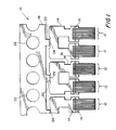
- Fig. 1 shows a portion of a strip of electrical contacts having been previously assembled. More particularly, the assembled contact strip 10 includes a group of fine diameter contact wires shown generally at 12.
- the wires are of a diameter of approximately 0.003 inches and are formed of palladium/silver alloy.
- each of the groups 12 there are twenty-two wires arranged side-by-side so that they are in physical contact with each other. Alternatively, the wires may be mutually spaced apart.
- Each group of wires is welded to a metal holder portion forming a mounting element 14 that is a thin gauge metal spring formed of a tempered copper or nickel based alloy.
- various other metal alloys can be used. While in this case it is palladium/silver alloy on a copper base strip, the wires could be tungsten or stainless steel or the like on a base strip formed of various other metals.
- the mounting elements 14 are in turn attached to a strip or band 18 of the same spring-like material at attachment elements 20.
- the band 18 is provided with sprocket holes, shown typically at 22, that are precisely located along the length thereof.
- the mounting elements 14 and the band 18 need not be separate elements, and the mounting elements and band can be integrally formed as one piece.
- the groups 12 are arranged at even intervals along the length of the band 18.
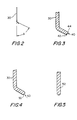
- Fig. 2 shows a single wire 30 that makes up the group of wire contacts 12 shown in Fig. 1.
- This wire 30 is bent at the head end through an angle A, which can typically be approximately 70°.
- the wire contacts can be supplied straight for subsequent bending after polishing.
- Fig. 3 is a close-up view in cross-section of the wire 30 of Fig. 2 showing that at the end portion 40 sharp corners such as at 42 and burrs such as at 44 caused by the manufactured process are originally present. It is these sharp corners 42 and burrs 44 that are desired to be eliminated from the finished product.
- Fig. 5 shows a close-up view in cross-section of a single wire 52 that is not bent but is straight. A group of these wires would be used to make up the contact group 12 of Fig. 1. This wire 52 has already been polished and the burrs and sharp corners have been removed and is then ready to be bent through any angle required by the particular application.
- Fig. 6 is a schematic representation of an embodiment of the present invention in which the assembled contact strip 10 bearing the mounting elements 14 and contact wires 12 attached to the mounting strip 18 is provided to the electro-chemical processing site.
- the assembled contact strip 10 is wound about a supply spool 60 that has upper and lower flanges 62 and 64, respectively.
- the supply spool 60 is mounted on a spindle 66 that is provided with suitable mounting elements to permit the supply spool 60 to be rotatably mounted thereon.
- the assembled contact strip 10 is then passed over a metering roller 68 that has a sprocket or the like, not shown, that engages with the sprocket holes 22 of the assembled contact strip 10.
- the metering roller could be a soft rubber roller that is rotated by friction with the assembled contact strip 10.
- the metering roller 68 is attached to a pulse generator 70 that provides output pulses on line 72 fed to the system controller 74, which may comprise a microprocessor.
- the assembled contact strip 10 is then passed uniformly into and through an electro-chemical polishing site 76 that performs the electro-chemical polishing on the tips of the contact wires, as described above.
- an assembled contact strip 110 includes a group of fine diameter wires, shown typically at 112. Each group of wires is welded to a metal holder portion 114.
- a few of the mounting elements 14, in this case three, are attached to a short, straight length or strip 118 of spring-like material at attachment elements 120.
- the strip 118 can have sprocket holes 122 formed therein.
- this embodiment shows three mounting elements 114 attached to the strip 118 fewer or more mounting elements could be employed with the strip length changing accordingly.
- the groups 112 are arranged at even intervals along the length of the band 118.
- the assembled contact strip 110 is fed to an electro-chemical polishing site 124 by a drive roller pair that includes a drive roller 126 and an idler roller 128.
- the drive roller 126 is driven by a motor 130 that is controlled by a system controller, not shown, such as controller 24 in the system of Fig. 6.
- the contact strip 110 is thus fed into the polishing site 124 where it is handled in a similar fashion as by the input system that is shown and the electro-chemical tip polishing is performed.
- the polished contact strip 110 is fed to the nip of a pair of output rollers that include a drive roller 132 and idler roller 134.
- the drive motor 132 is driven by a motor 136 under control of the system controller, not shown.
- the output rollers 132, 134 then transport the contact strip 110 to a collection location, such as a conveyor belt 138 driven by a motor 140 under control of the system controller, not shown.
- the input rollers and output rollers can transport the contact strips 110 by friction or drive pins, shown typically at 142, can be provided on the drive rollers 126, 132 for interaction with the sprocket holes 122 formed in the metal strip 118. Nevertheless, because the rate of passage of the contact strips 110 through the polishing site is not absolutely set by the input and output rates, the input and output drive rates can be met using friction drive rollers.
Landscapes
- Engineering & Computer Science (AREA)
- Manufacturing & Machinery (AREA)
- Finish Polishing, Edge Sharpening, And Grinding By Specific Grinding Devices (AREA)
- Electrical Discharge Machining, Electrochemical Machining, And Combined Machining (AREA)
Applications Claiming Priority (2)
| Application Number | Priority Date | Filing Date | Title |
|---|---|---|---|
| US229718 | 1999-01-13 | ||
| US09/229,718 US6386959B2 (en) | 1999-01-13 | 1999-01-13 | Feeding system for electro-chemically polishing contact tips |
Publications (1)
| Publication Number | Publication Date |
|---|---|
| EP1020965A1 true EP1020965A1 (en) | 2000-07-19 |
Family
ID=22862422
Family Applications (1)
| Application Number | Title | Priority Date | Filing Date |
|---|---|---|---|
| EP99650059A Withdrawn EP1020965A1 (en) | 1999-01-13 | 1999-06-24 | Feeding system for electro-chemically polishing contact tips |
Country Status (3)
| Country | Link |
|---|---|
| US (1) | US6386959B2 (enExample) |
| EP (1) | EP1020965A1 (enExample) |
| JP (1) | JP2000202714A (enExample) |
Families Citing this family (3)
| Publication number | Priority date | Publication date | Assignee | Title |
|---|---|---|---|---|
| DE10157320A1 (de) * | 2001-11-23 | 2003-06-12 | Kern & Liebers | Verfahren zum Herstellen von Mikroschleifkontakten |
| CN111408804B (zh) * | 2020-04-28 | 2020-12-18 | 常州工学院 | 一种调隙式弯孔电解加工装置及方法 |
| CN111687738B (zh) * | 2020-06-24 | 2021-03-19 | 深圳市创益通技术股份有限公司 | 5g端子自动抛光机 |
Citations (3)
| Publication number | Priority date | Publication date | Assignee | Title |
|---|---|---|---|---|
| US5189278A (en) * | 1990-06-29 | 1993-02-23 | Hugo Kern & Liebers Gmbh & Co. Platinen- Und Federnfabrik | Method for edge rounding of springs |
| WO1997037847A1 (en) * | 1996-04-05 | 1997-10-16 | Kuhlmann Wilsdorf Doris | Continuous metal fiber brushes |
| US5796065A (en) * | 1995-05-29 | 1998-08-18 | Jasty R & D Inc. | Apparatus for producing contact/connection member for electric and electronic parts |
Family Cites Families (24)
| Publication number | Priority date | Publication date | Assignee | Title |
|---|---|---|---|---|
| US2434286A (en) | 1943-08-12 | 1948-01-13 | Bell Telephone Labor Inc | Method of forming a point at the end of a wire |
| US2628936A (en) | 1949-05-06 | 1953-02-17 | Bell Telephone Labor Inc | Method of forming a point at the end of a wire |
| BE506706A (enExample) | 1950-10-28 | |||
| US2811702A (en) * | 1956-06-21 | 1957-10-29 | Malco Tool & Mfg Co | Terminal pin for printed circuit board |
| US3550856A (en) * | 1968-07-03 | 1970-12-29 | Amp Inc | Electrical connector feed strip assembly |
| US3606000A (en) * | 1968-07-03 | 1971-09-20 | Amp Inc | Thermoformed plastic covered connectors |
| US3666090A (en) * | 1970-01-27 | 1972-05-30 | Coilcraft Inc | Coil form and carrier strip |
| US4021095A (en) * | 1974-02-21 | 1977-05-03 | Amp Incorporated | Stacked carrier strip assembly |
| US4044888A (en) * | 1975-10-23 | 1977-08-30 | Schachter Herbert I | Prefabricated contacts for printed circuit card connectors |
| US4242535A (en) * | 1979-09-27 | 1980-12-30 | Amp Incorporated | Connection of wires to components having two prongs |
| US4375396A (en) | 1981-11-17 | 1983-03-01 | The United States Of America As Represented By The Administrator Of The National Aeronautics And Space Administration | Thin wire pointing method |
| US4480150A (en) * | 1982-07-12 | 1984-10-30 | Motorola Inc. | Lead frame and method |
| DE3332804C2 (de) | 1983-09-12 | 1986-10-23 | Hollingsworth Gmbh, 7265 Neubulach | Verfahren zum Behandeln der Kanten eines Sägezahndrahtes für Garnituren in Textilmaschinen |
| US4600971A (en) * | 1984-05-11 | 1986-07-15 | Amp Incorporated | Lead frames with dielectric housings molded thereon |
| US4611262A (en) * | 1984-05-11 | 1986-09-09 | Amp Incorporated | Electrical circuit package for greeting cards |
| US4752367A (en) | 1987-05-08 | 1988-06-21 | Cation Corporation | Apparatus and method for electrochemically smoothing or finishing a surface of a conductive metal part |
| JP2573016B2 (ja) | 1988-02-27 | 1997-01-16 | アンプ インコーポレーテッド | マイクロ入出力ピンおよびその製造方法 |
| JPH033723A (ja) * | 1989-05-30 | 1991-01-09 | Kawasaki Steel Corp | 帯板の連続研磨装置 |
| US5105537A (en) | 1990-10-12 | 1992-04-21 | International Business Machines Corporation | Method for making a detachable electrical contact |
| JPH079229A (ja) * | 1993-06-28 | 1995-01-13 | Shin Meiwa Ind Co Ltd | 型材のフランジ自動切削装置 |
| JP2696197B2 (ja) * | 1993-08-27 | 1998-01-14 | ユケン工業株式会社 | 連続電解研磨方法及び連続電解研磨装置 |
| US5503895A (en) * | 1993-09-20 | 1996-04-02 | Bi-Link Metal Specialties | Supply feedstock for workpiece finishing machine |
| JPH09106874A (ja) * | 1995-05-29 | 1997-04-22 | Justy:Kk | 電気電子部品用接点/接続部材の製造装置および電気電子部品用接点/接続部材 |
| JP3244426B2 (ja) * | 1996-03-26 | 2002-01-07 | 信越半導体株式会社 | ワイヤソー用ワイヤの製造方法及びワイヤソー用ワイヤ |
-
1999
- 1999-01-13 US US09/229,718 patent/US6386959B2/en not_active Expired - Fee Related
- 1999-06-24 EP EP99650059A patent/EP1020965A1/en not_active Withdrawn
- 1999-08-17 JP JP11230879A patent/JP2000202714A/ja active Pending
Patent Citations (3)
| Publication number | Priority date | Publication date | Assignee | Title |
|---|---|---|---|---|
| US5189278A (en) * | 1990-06-29 | 1993-02-23 | Hugo Kern & Liebers Gmbh & Co. Platinen- Und Federnfabrik | Method for edge rounding of springs |
| US5796065A (en) * | 1995-05-29 | 1998-08-18 | Jasty R & D Inc. | Apparatus for producing contact/connection member for electric and electronic parts |
| WO1997037847A1 (en) * | 1996-04-05 | 1997-10-16 | Kuhlmann Wilsdorf Doris | Continuous metal fiber brushes |
Also Published As
| Publication number | Publication date |
|---|---|
| US6386959B2 (en) | 2002-05-14 |
| JP2000202714A (ja) | 2000-07-25 |
| US20010053656A1 (en) | 2001-12-20 |
Similar Documents
| Publication | Publication Date | Title |
|---|---|---|
| US4274575A (en) | Method of manufacturing brush seals | |
| US4485757A (en) | Process and apparatus for applying relatively hard particles to a circular wire-like form or a wire-like form without longitudinal edges, as well as wire-shaped saw | |
| US5823082A (en) | Apparatus for manufacturing support members for razor blades | |
| US5522130A (en) | Laser positioning system for wire cutting and stripping apparatus | |
| US4233486A (en) | Traveling-wire electrical discharge machine | |
| JP2001500808A (ja) | カテーテル、誘導線などに切れ目を形成する方法および装置 | |
| US4431894A (en) | Method of and apparatus for automatically threading a continuous electrode wire in an electroerosion machine | |
| KR930010587B1 (ko) | 공작 기계상의 와이어 또는 스트립형 절단전극의 안내장치 | |
| JPH06297230A (ja) | 長尺体の切断装置 | |
| US6386959B2 (en) | Feeding system for electro-chemically polishing contact tips | |
| EP0621096B1 (en) | Device for forming drilled needle blanks | |
| JP2000123948A (ja) | 自動切断圧着装置 | |
| US4242558A (en) | Device for breaking off the wire-like or strip-like electrode in an electro-erosion machine | |
| JPH07272816A (ja) | 自動結線装置用ケーブル送出し装置 | |
| JPH10183390A (ja) | 長尺金属条体のパターンめっき方法 | |
| JPH1046386A (ja) | マスキングテ−プ貼付方法及びそれを実施するマスキングテ−プ貼付装置 | |
| JPH0319015B2 (enExample) | ||
| JP3440813B2 (ja) | 多頭式端子帯供給装置 | |
| JP2000202714A5 (enExample) | ||
| KR102451087B1 (ko) | 와이어 가공 장치 | |
| KR100900634B1 (ko) | 스트립 용접기의 용접휠 크리닝장치 | |
| JP2003025210A (ja) | ワイヤソー装置及び同時切断方法 | |
| JPS59232728A (ja) | ワイヤカット放電加工に於けるワイヤ電極の位置決めガイド装置 | |
| JP2001038524A (ja) | 線材を所定長さに計尺し切断する装置 | |
| US4378083A (en) | Wiring machine wire placing head |
Legal Events
| Date | Code | Title | Description |
|---|---|---|---|
| PUAI | Public reference made under article 153(3) epc to a published international application that has entered the european phase |
Free format text: ORIGINAL CODE: 0009012 |
|
| AK | Designated contracting states |
Kind code of ref document: A1 Designated state(s): DE FR GB |
|
| AX | Request for extension of the european patent |
Free format text: AL;LT;LV;MK;RO;SI |
|
| 17P | Request for examination filed |
Effective date: 20010119 |
|
| AKX | Designation fees paid |
Free format text: DE FR GB |
|
| GRAH | Despatch of communication of intention to grant a patent |
Free format text: ORIGINAL CODE: EPIDOS IGRA |
|
| GRAH | Despatch of communication of intention to grant a patent |
Free format text: ORIGINAL CODE: EPIDOS IGRA |
|
| STAA | Information on the status of an ep patent application or granted ep patent |
Free format text: STATUS: THE APPLICATION IS DEEMED TO BE WITHDRAWN |
|
| 18D | Application deemed to be withdrawn |
Effective date: 20030225 |