EP1020607B1 - Beschlag für ein rahmenloses Glaselement - Google Patents
Beschlag für ein rahmenloses Glaselement Download PDFInfo
- Publication number
- EP1020607B1 EP1020607B1 EP00100835A EP00100835A EP1020607B1 EP 1020607 B1 EP1020607 B1 EP 1020607B1 EP 00100835 A EP00100835 A EP 00100835A EP 00100835 A EP00100835 A EP 00100835A EP 1020607 B1 EP1020607 B1 EP 1020607B1
- Authority
- EP
- European Patent Office
- Prior art keywords
- glass
- glazing element
- screw
- fastening
- element according
- Prior art date
- Legal status (The legal status is an assumption and is not a legal conclusion. Google has not performed a legal analysis and makes no representation as to the accuracy of the status listed.)
- Expired - Lifetime
Links
- 239000011521 glass Substances 0.000 claims abstract description 211
- 239000000463 material Substances 0.000 claims description 7
- 230000000295 complement effect Effects 0.000 claims description 4
- 238000003825 pressing Methods 0.000 claims description 3
- 238000005192 partition Methods 0.000 claims 1
- 239000005336 safety glass Substances 0.000 description 19
- 125000006850 spacer group Chemical group 0.000 description 12
- 238000004519 manufacturing process Methods 0.000 description 7
- 238000010276 construction Methods 0.000 description 6
- 239000011888 foil Substances 0.000 description 4
- 241000591215 Acraea andromacha Species 0.000 description 3
- 239000013013 elastic material Substances 0.000 description 3
- 229920002472 Starch Polymers 0.000 description 2
- 239000000853 adhesive Substances 0.000 description 2
- 230000001070 adhesive effect Effects 0.000 description 2
- 238000004140 cleaning Methods 0.000 description 2
- 239000011248 coating agent Substances 0.000 description 2
- 238000000576 coating method Methods 0.000 description 2
- 239000007888 film coating Substances 0.000 description 2
- 238000009501 film coating Methods 0.000 description 2
- 238000007789 sealing Methods 0.000 description 2
- 239000007787 solid Substances 0.000 description 2
- 235000019698 starch Nutrition 0.000 description 2
- 239000008107 starch Substances 0.000 description 2
- 238000003860 storage Methods 0.000 description 2
- 238000011109 contamination Methods 0.000 description 1
- 239000003599 detergent Substances 0.000 description 1
- 238000011161 development Methods 0.000 description 1
- 238000005553 drilling Methods 0.000 description 1
- 230000005489 elastic deformation Effects 0.000 description 1
- 238000009434 installation Methods 0.000 description 1
- 230000013011 mating Effects 0.000 description 1
- 239000002184 metal Substances 0.000 description 1
- 239000007769 metal material Substances 0.000 description 1
- 239000000126 substance Substances 0.000 description 1
Images







Classifications
-
- B—PERFORMING OPERATIONS; TRANSPORTING
- B32—LAYERED PRODUCTS
- B32B—LAYERED PRODUCTS, i.e. PRODUCTS BUILT-UP OF STRATA OF FLAT OR NON-FLAT, e.g. CELLULAR OR HONEYCOMB, FORM
- B32B17/00—Layered products essentially comprising sheet glass, or glass, slag, or like fibres
- B32B17/06—Layered products essentially comprising sheet glass, or glass, slag, or like fibres comprising glass as the main or only constituent of a layer, next to another layer of a specific material
- B32B17/10—Layered products essentially comprising sheet glass, or glass, slag, or like fibres comprising glass as the main or only constituent of a layer, next to another layer of a specific material of synthetic resin
- B32B17/10005—Layered products essentially comprising sheet glass, or glass, slag, or like fibres comprising glass as the main or only constituent of a layer, next to another layer of a specific material of synthetic resin laminated safety glass or glazing
- B32B17/10009—Layered products essentially comprising sheet glass, or glass, slag, or like fibres comprising glass as the main or only constituent of a layer, next to another layer of a specific material of synthetic resin laminated safety glass or glazing characterized by the number, the constitution or treatment of glass sheets
- B32B17/10036—Layered products essentially comprising sheet glass, or glass, slag, or like fibres comprising glass as the main or only constituent of a layer, next to another layer of a specific material of synthetic resin laminated safety glass or glazing characterized by the number, the constitution or treatment of glass sheets comprising two outer glass sheets
-
- B—PERFORMING OPERATIONS; TRANSPORTING
- B32—LAYERED PRODUCTS
- B32B—LAYERED PRODUCTS, i.e. PRODUCTS BUILT-UP OF STRATA OF FLAT OR NON-FLAT, e.g. CELLULAR OR HONEYCOMB, FORM
- B32B17/00—Layered products essentially comprising sheet glass, or glass, slag, or like fibres
- B32B17/06—Layered products essentially comprising sheet glass, or glass, slag, or like fibres comprising glass as the main or only constituent of a layer, next to another layer of a specific material
- B32B17/10—Layered products essentially comprising sheet glass, or glass, slag, or like fibres comprising glass as the main or only constituent of a layer, next to another layer of a specific material of synthetic resin
- B32B17/10005—Layered products essentially comprising sheet glass, or glass, slag, or like fibres comprising glass as the main or only constituent of a layer, next to another layer of a specific material of synthetic resin laminated safety glass or glazing
- B32B17/10165—Functional features of the laminated safety glass or glazing
- B32B17/10293—Edge features, e.g. inserts or holes
-
- E—FIXED CONSTRUCTIONS
- E05—LOCKS; KEYS; WINDOW OR DOOR FITTINGS; SAFES
- E05D—HINGES OR SUSPENSION DEVICES FOR DOORS, WINDOWS OR WINGS
- E05D5/00—Construction of single parts, e.g. the parts for attachment
- E05D5/02—Parts for attachment, e.g. flaps
- E05D5/0246—Parts for attachment, e.g. flaps for attachment to glass panels
-
- E—FIXED CONSTRUCTIONS
- E06—DOORS, WINDOWS, SHUTTERS, OR ROLLER BLINDS IN GENERAL; LADDERS
- E06B—FIXED OR MOVABLE CLOSURES FOR OPENINGS IN BUILDINGS, VEHICLES, FENCES OR LIKE ENCLOSURES IN GENERAL, e.g. DOORS, WINDOWS, BLINDS, GATES
- E06B3/00—Window sashes, door leaves, or like elements for closing wall or like openings; Layout of fixed or moving closures, e.g. windows in wall or like openings; Features of rigidly-mounted outer frames relating to the mounting of wing frames
- E06B3/02—Wings made completely of glass
-
- E—FIXED CONSTRUCTIONS
- E06—DOORS, WINDOWS, SHUTTERS, OR ROLLER BLINDS IN GENERAL; LADDERS
- E06B—FIXED OR MOVABLE CLOSURES FOR OPENINGS IN BUILDINGS, VEHICLES, FENCES OR LIKE ENCLOSURES IN GENERAL, e.g. DOORS, WINDOWS, BLINDS, GATES
- E06B3/00—Window sashes, door leaves, or like elements for closing wall or like openings; Layout of fixed or moving closures, e.g. windows in wall or like openings; Features of rigidly-mounted outer frames relating to the mounting of wing frames
- E06B3/54—Fixing of glass panes or like plates
- E06B3/5436—Fixing of glass panes or like plates involving holes or indentations in the pane
-
- E—FIXED CONSTRUCTIONS
- E05—LOCKS; KEYS; WINDOW OR DOOR FITTINGS; SAFES
- E05D—HINGES OR SUSPENSION DEVICES FOR DOORS, WINDOWS OR WINGS
- E05D5/00—Construction of single parts, e.g. the parts for attachment
- E05D5/02—Parts for attachment, e.g. flaps
- E05D5/0246—Parts for attachment, e.g. flaps for attachment to glass panels
- E05D2005/0253—Parts for attachment, e.g. flaps for attachment to glass panels the panels having conical or stepped recesses
-
- E—FIXED CONSTRUCTIONS
- E05—LOCKS; KEYS; WINDOW OR DOOR FITTINGS; SAFES
- E05D—HINGES OR SUSPENSION DEVICES FOR DOORS, WINDOWS OR WINGS
- E05D7/00—Hinges or pivots of special construction
- E05D7/10—Hinges or pivots of special construction to allow easy separation or connection of the parts at the hinge axis
- E05D7/1044—Hinges or pivots of special construction to allow easy separation or connection of the parts at the hinge axis in an axial direction
Definitions
- the invention relates to a glass element with a fitting according to the preamble of claim 1
- US-A-2,609,069 is a glass element with a fitting for a fastening device for a glass wing according to the preamble of claim 1.
- To attach the fitting is one in a hole in the glass wing, already provided between the discs holding bush provided with mounting screws connect the fittings to the retaining bush.
- a glass wing with a fastening device is known, at the two bushes from opposite sides in a wing hole intervene, and these are bolted together. At any of the sockets the fitting of a fitting part is provided
- connection of frameless glass elements with a component is often problematic, since the attachment point on the glass element as possible no relative movement, even over a long period, may have, because the glass elements must not sit opposite the component they hold become.
- the fixed component for example, by a door frame or a wall is formed, are fixedly arranged glass elements in terms the attachment of a fastener unproblematic, because usually they do not act on such high forces as they are movable, e.g. rotatable, pivotable or displaceable arranged in the component glass elements.
- safety glass elements made of thermal prestressed glass panes
- have a compressive residual stress at the Surface whereby they have a good impact resistance and in the case of a Break no longer in large, sharp-edged shards, but in small, blunt-edged Glass crumbs crumble.
- the two-pane safety glass arranged a tough elastic film between the glass sheets or the toughened safety glass glued on a viscoplastic film, so that the individual glass crumbs are held together when the glass element breaks become. This means that the glass element does not break when it breaks coincides but the glazed opening remains closed.
- An object of the present invention is to provide a glass element with a fitting to provide a fastening device for a preferably frameless Glass element that has a solid and also over a long period of time ensures perfect and immovable connection with the glass element.
- a perfect connection between the fitting and the glass element is obtained by the fact that the fastening device formed on the glass element Attack surfaces attacks, which formed free of elastic film are. By the direct attack of the fastening device on the hard Glass surface will be an elastic deformation of the elastic film and thus shifting the fastening device on the glass element with certainty avoided.
- a simple and easy to install arrangement of the fastening device on the glass element is provided according to feature by the fastening device forms a clamping connection with the glass element, wherein at least one of the glass panes two attack surfaces are arranged.
- This clamp connection the fastening device with the glass element is corresponding a feature of the invention in particular frictionally and / or positively formed.
- the only frictional clamping connection has plane attack surfaces the glass sheet on, with corresponding and these attack surfaces clamped adapted mating surfaces of the fastening device are.
- Such a purely frictional clamping connection is in particular for Glass elements with relatively low weight and / or fixed glass elements applicable to which no major external forces act.
- a clamping connection is formed so that in a glass element from several panes of glass with at least one intermediate elastic film on only one glass pane at least two attack surfaces or at least two attack surfaces are formed on a plurality of glass panes are.
- the attack surfaces of the glass panes for the clamp connection are freed from the elastic film by mechanical or chemical action, unless they are already formed accordingly during the production of the glass element are.
- two glass panes which have a interconnected film are connected, in each case at least two attack surfaces arranged, between the glass panes a the film mögliehsee relieving spacer element is connected to the respective at least one or two attack surfaces are formed or attack.
- a spacer is advantageously captive in the manufacture of the glass element built-in and depending on the design, either fixed with a glass pane or connected to the other glass pane or to both glass panes become.
- the attack surfaces on the opposite sides of the Glass pane may for example be provided so that they as at least two facing surfaces to the glass surface or as two oblique to the glass surface Attack surfaces or as one to the glass plane and one to the glass surface oblique attack surface are formed.
- the fastening device to the attack surfaces complementary mounting surfaces which have a clamping device, preferably with a Screw, are clamped to each other.
- the oblique to the surface of the Glass pane extending attack surfaces can be designed arbitrarily, for example as square, rectangular or oval depressions.
- a simple in construction embodiment is obtained when the positive Clamping connection has a recess in the supporting glass pane and between the recess and the plane glass surface at least one oblique Inner surface is arranged, with a complementary oblique outer surface a part of the fastening device cooperates.
- This recess can be arbitrarily shaped, for example as a bore or as a rectangle, in particular Square. With square training is a correspondingly executed Mounting part arranged non-rotatably in this recess.
- the supporting glass formed larger as the non-supporting glass sheet and has been freed of elastic film Attack surfaces, which form the clamping surfaces for a clamping shoe.
- this clamp connection can easily with oblique to the plane glass surface extending, formed by depressions or openings attack surfaces be combined, in the corresponding projections of the clamping shoe engage, creating an additional positive connection for this fastening device is created.
- a simple, shapely and particularly durable connection of the fastening device with the supporting glass element according to the invention thereby created that the fastening device of one or more, preferably consists of two fastening islands, which are in recesses of the glass element are arranged.
- These mounting islands is a Fastening device arranged in a center of the glass element Recess, preferably bore, is inserted and in this position with the Glass panes is anchored.
- the fastening islands serve to further fittings to be attached to the glass element, i. they are firmly anchored formed further fittings.
- Each attachment island consists of at least two components that interact with the surfaces of the supporting glass pane. In a simple way, the clamping connection is achieved when each mounting island has two screw flanges, which can be connected together are formed. Instead of the screw flanges can also rivet-like Flanges are provided by compressing a mounting island form.
- each mounting island a threaded sleeve assigned, which provided with a pressure surface forming a mounting collar and connectable with the screw flanges.
- the fastening device are created according to the invention thereby that the threaded sleeve is formed as a spacer element, during manufacture the glass element is inserted captive and with the mounting collar in a space bounded by the two glass panes, the free of elastic film is formed.
- the mounting collar of the threaded sleeve adapted to the shape of the attack surface of the glass and is optional against one or the other glass pane or against both glass panes formed clampable.
- Another very advantageous construction of the fastening device is feature created by the fact that in a glass element with a supporting Glass pane and a non-load-bearing glass pane the supporting glass pane a trained as a counterbore recess with a smaller diameter has as the bore of the non-supporting glass and the mounting collar the threaded sleeve against the attack surface formed by or pressed against a frusto-conical inner surface by means of the screw is, while the other fferflansch essentially only for recording a fitting part of the fitting is arranged.
- the components of the fastening device preferably made of a hard metallic material are made and the metal surfaces of some components the glass surface during assembly and / or on the glass element
- the attack surface the glass pane is not damaged by compressive stress, preferably made of a hard plastic.
- the molded sockets and Pressure plates thus prevent direct contact between the metallic Components of the attachment island and the engagement surfaces of the glass element, However, because of their inelasticity, they simultaneously immovable fixation of the fitting to the glass element safely.
- the fitting part in the region of each mounting island with respect to the outer thread diameter of a fastening screw provided with a larger bore thereby reducing the connection the fitting with the glass element a simple and effective adjustment for the fitting relative to the glass element and also a compensation the manufacturing tolerances is created.
- the glass element can be constructed in various ways; e.g. can the glass element from a glass sheet without or with foil coating or from several Glass panes with intervening films exist. Because of that Area of the fastening device no foil is arranged or the film is removed, which is connected to the fastening device glass to a carrying glass pane.
- the glass element thus has at least one load-bearing Glass pane and optionally additionally one or more non-structural Glass panes on.
- an advantageous construction thereby created that the glass element two glass panes with different thickness , wherein the clamping connection for the fitting preferably at the stronger glass pane is arranged.
- the connection between the fastening device and the remaining fittings is done in a simple manner in that each screw flange with a centrally located internal thread is provided, in which engages a fastening screw for the fitting parts.
- the known screw fuses be applied, e.g. Adhesive fuses.
- the fastening islands and the other fitting parts designed so that the fittings adjustable are and can be mounted in 180 ° rotated position. Further is preferably between the fitting and the glass element a seal arranged, thereby preventing the ingress of dirt or detergent Cleaning the glass element is avoided.
- the fitting can be offered as a kit.
- the components of the fastening device modular design are. This means that many of the components are universal for all conceivable Applications are used, i. e.g. both for laminated safety glass as also for single-pane glass elements.
- This modular design allows the number of components for significantly reduce the entire product range of fastening device, what leads to cost advantages in development, production and storage.
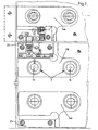
- an upper glass member 1a is shown as a fixed panel blade connected to a door frame or a wall, and a lower glass member 1b constitutes a revolving door.
- These glass elements 1a, 1b are executed frameless, with each fitting parts 4a, 4b, 4c of the fittings with their fasteners 3 on the one hand firmly connected to the glass elements 1a, 1b and on the other hand either with the door frame, or they access via an upper door bearing 23 with a Pivot in a formed by the fitting of the fixed-field blade pivot bearing and with the pivot of the lower door bearing 24, for example, in a floor spring, a.
- fitting parts 4a, 4b, 4c are fixedly connected to the glass elements 1a, 1b, wherein the fittings for a variety of applications may be formed, for example as a turn, slide, swing or tilt fittings for doors or windows.
- the fastening means 3 In order to ensure proper functioning, in particular of the pivotable wings, the fastening means 3 must form an immovable connection with the fittings, and it is preferably each fitting part 4a, 4b, 4c assigned two fastening islands 11.
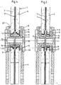
- FIG. 2 shows a fastening device 3 designed as a fastening island 11, which is firmly connected to a glass element 1.
- the glass element 1 is a single-pane safety glass, which consists of a supporting glass pane 6 with glued elastic film 7.
- the fastening island 11 has a first screw flange 12 with an inner and an outer thread and a second screw flange 13 with an inner thread.
- the surface of the glass sheet 6 is formed free of elastic film 7, so that both the form of socket 14 and the pressure plate 15 rest directly on the plane attack surfaces 8 and 9.
- the glass sheet 6 is provided with a recess 10 formed as a bore into which the provided with the form of socket 14 screw 14 is inserted and then screwed tightly with the screw 12.
- This screw is advantageously carried out with a predetermined torque and secured against loosening.
- the attachment of the fitting part 4 takes place with the fastening screws 18 and 19, which are screwed into the internal thread of the screw 12.
- the holes of the fitting part 4, through which the fastening screws 18 and 19 engage, formed larger than the external thread of these fastening screws formed larger than the external thread of these fastening screws.
- a seal 20 is still provided, which protects the internal parts of the fitting from contamination and is advantageous in the cleaning of the glass element.
- the fitting part 4 shown in Figure 2 can in the same way to glass elements 1 with one or more discs 5, 6, no film coating 7 or no intermediate elastic film 7 have to be used.
- the mounting pad 11 of this embodiment allows in some A variation of the thickness of the disc 6, wherein the screw flanges 12, 13 and the fastening screws 18, 19 are used unchanged. The same thing applies to the embodiment of Figure 3, where using the same Screw flanges 12, 13 and mounting screws 18, 19 even larger
- the embodiment shown in Figure 3 shows a glass element 1, which has a non-supporting glass pane 5 and a supporting glass pane 6, wherein the two glass sheets 5 and 6 are interconnected by an intermediate elastic film 7.
- the non-load-bearing glass pane 5 is provided with a larger bore for receiving a threaded sleeve 16 than the bore formed in the supporting glass pane 6 by the recess 10.
- the threaded sleeve 16 has a fastening collar 17 and is provided with an internal thread into which the identically designed screw flanges 12 and 13 engage with their external threads.
- the supporting glass pane 6 is provided with the attack surfaces 8 and 9 formed free of elastic film 7, wherein the first attack surface 8 present on the film side acts on the attachment surface formed by the fastening collar 17 of the threaded sleeve 16 via a forming bushing 14 and the first screw flange 12 via a pressure washer 15 acts on the second engagement surface 9.
- the first attack surface 8 present on the film side acts on the attachment surface formed by the fastening collar 17 of the threaded sleeve 16 via a forming bushing 14 and the first screw flange 12 via a pressure washer 15 acts on the second engagement surface 9.
- a free space 2 is limited, in the screw for securing and sealing, for example before screwing the second screw 13 a preferably hard elastic material is introduced.
- the hard-elastic material causes a degree of adhesion between the threaded sleeve to some extent 16 and the non-supporting disc 5 and also an additional seal the fastening island 11.
- the second screw 13 is with a pressure plate screwed against the first contact surface 8, but with low torque, so that no additional tension on the laminated safety glass is exercised.
- To attach the fitting part 4 are two such mounting islands 11 connected to the glass element 1.
- a threaded sleeve 16 with a spacer element formed by the fastening collar 17 is arranged in a free space bounded by the two glass panes 5 and 6 and is captively inserted during the production of the glass element.
- the engagement surfaces 8 of the glass sheets 5 and 6 have frustoconical inner surfaces 21, which are free of elastic film 7.
- Formed as a spacer element mounting collar 17 of the threaded sleeve 16 is provided with complementary frusto-conical outer surfaces 22, and between the inner surfaces 21 and the outer surfaces 22 form sleeves 14 are arranged.
- the first screw 12 is screwed into the threaded sleeve 16, which is provided for countering with a tool with holes.
- the threaded sleeve 16 and the screw 12 are clamped together with a predetermined torque, whereby the firm connection with the glass sheet 6 is made. It can also be a solid connection with the glass sheet 5 are formed when screw 13 is screwed tightly to the threaded sleeve 16, or both glass sheets 5 and 6 are clamped with the inner surfaces 21 against the outer surfaces 22 of the mounting collar.
- the subsequent connection of the fitting part 4 with the mounting island is already described in the embodiments according to Figures 2 and 3 with corresponding reference numerals.
- Figure 5 differs from that of Figure 4 essentially in that the captive connected to the glass element 1 threaded sleeve 16 is provided with a mounting collar 17 which forms a rectangular spacer in section. The remaining construction and the mode of operation are described in FIG.
- the supporting glass pane 6 of the laminated safety glass element 1 is provided with a recess 10 designed as a counterbore for receiving the fastening island 11, which thus has a frusto-conical inner surface 21 which forms the contact surface 8 which is free of elastic foil 7.
- the diameter of the bore of the second glass pane 5 is greater than the diameter of the recess 10 of the first glass pane 6.
- the threaded sleeve 16 has a mounting collar 17, which has a frusto-conical outer surface 22 which corresponds to the frusto-conical inner surface of the molded socket 14.
- the threaded sleeve which is described in more detail in Figure 11 , has an internal thread, in which from the sides of the supporting disc 6, a screw 12 is screwed. The screw is supported with its disk-shaped area on a pressure plate 15.
- the pressure disk 15 is annular and, like the molded bushing 14, consists of a hard material which protects the engagement surface 9 of the supporting glass pane 6 from direct contact with the screw flange 12.
- the mounting of the mounting pad 11 is effected in that the threaded sleeve 16 is bolted to the first screw 12, wherein by pressing the mold sleeve 14 against the first frustoconical surface attack 8 and by pressing the pressure washer 15 against the plane second attack surface 9, a firm connection of these parts 12, 16 is made with the supporting glass 6.
- the frusto-conical corresponding surfaces also ensures that the fastening island is centered and immovably fixed in the glass element.
- the second screw 13 is screwed from the sides of the non-load-bearing glass pane 5 in the internal thread of the threaded sleeve 16 and is located with the interposition of a second pressure plate 15 on the flat outer surface of the non-supporting glass pane 5 in Appendix.
- the second pressure plate 15 has only sealing function
- the exemplary embodiment according to FIG. 7 differs from the exemplary embodiment according to FIG. 6 in that the supporting glass pane 6 of the glass element 1 has a greater thickness than the non-load-bearing glass pane 5.
- the threaded sleeve 16 is corresponding to the thicknesses of the glass panes 5, 6 opposite the threaded sleeve 16 formed modified in the embodiment of Figure 6 and is described in more detail in Figure 12 .
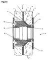
- a fitting part 4 is mounted on the glass element 1 by means of the fastening screws 18, 19, which are screwed into the fastening island 11.
- Glass element 1 and mounting pad 11 correspond to the embodiment shown in Figure 7.
- the fastening screws 18, 19 each have an external thread which engage through holes 38 located in the fitting part 4 into corresponding internal threads of the screw flanges.
- the fitting part 4 is clamped by means of fastening screws 18, 19 with respect to the screw flanges 12, 13, ie the fitting part has no direct contact with the glass element 1.
- the frictional connection takes place via the threaded sleeve 16 and the screw flanges 12, 13.
- the gaps between the fitting part 4 and the disks 5, 6 are sealed by a seal 20 inserted there.
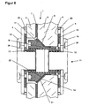
- the embodiment of Figure 9 differs from the embodiment of Figure 8, characterized in that the glass element 1 is formed as a single-pane glass element.
- the supporting disc 6 is likewise clamped by means of a threaded sleeve 16, which is adapted in the glass element 1 and is described in detail in Figure 13 , and a first screw 13 with the interposition of a molded sleeve 14 and a first pressure plate 15 braced.
- the second screw flange 12 is screwed into the threaded sleeve 16, wherein a second pressure plate 15 is arranged between the second screw flange 12 and the glass pane 6.
- the fitting 4 is, as described in the embodiment of Figure 8, mounted by means of fastening screws 18, 19 and sealed by means of seals 20 against the glass 6.
- the embodiment in Figure 10 also shows the attachment of a fitting part 4 on a single-pane glass element 1, wherein the glass sheet 6 is formed here stronger than the glass pane of the embodiment described above. Accordingly, the threaded sleeve 16 is modified with respect to the preceding embodiment and is described in more detail in Figure 14 .
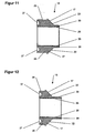
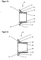
- the threaded sleeves 16 already shown in the installed state in FIGS. 6 to 10 are described separately.
- the threaded sleeve 16 has a cylindrical portion 39, to which a frusto-conical mounting collar 17 with frustoconical outer surface 22 connects.
- a cylindrical spacer collar 25 connects to the mounting collar 17.
- the threaded sleeve 16 On the inner wall of its through hole, the threaded sleeve 16 has an internal thread 26; this can be arranged continuously or only in the end regions of the threaded sleeve 16.
- the threaded sleeves of FIGS. 11 and 12 are intended for use with laminated safety glass elements.
- the threaded sleeve 16 shown in Figure 11 of the spacer collar 25 is formed approximately as long as mounting collar 17 and cylindrical portion 39 together; this threaded sleeve 16 is intended for use in laminated safety glass elements consisting of two approximately or exactly the same thickness discs. If the laminated safety glass element has two disks of different thickness, the use of the threaded sleeve 16 according to FIG. 12 is provided. Since it makes sense that the stronger disc is the supporting disc, this threaded sleeve 16 has a shorter spacer collar 25 and a longer cylindrical portion 39 in accordance with the ratio of the thicknesses of the discs.
- Figures 13 and 14 show threaded sleeves 16 for use with single pane glass elements. Accordingly, these threaded sleeves 16 have no Distanzbund.
- the length of the cylindrical portion 39 depends on the thickness of the glass sheet. While the threaded sleeve of FIG. 13 is intended for use with a relatively low thickness disc, in the threaded sleeve 16 shown in FIG. 14 , the cylindrical portion is made longer, so that it can be used with relatively thick discs.
- the thickness of the glass element can vary to some extent for each threaded sleeve shown; This depends on the configuration of the other components, in particular on the length of the external thread of the screw flanges described below.
- threaded sleeve 16 Alternatively, other, not shown embodiments of the threaded sleeve 16 possible.
- a continuous cylindrical design the threaded sleeve conceivable without a mounting collar, the bearing Slice the glass element directly between the screwed into the threaded sleeve Screw flanges is clamped.
- FIG. 15 shows a detail of the molded bushing 14 already shown in FIGS. 6 to 10 when installed.
- the molded sleeve has a cylindrical and an adjoining frustoconical region.
- the inner diameter of the cylindrical portion of the mold sleeve 14 is equal to the outer diameter of the cylindrical portion of the threaded sleeves described above, and the outer diameter of the cylindrical portion of the molded sleeve is slightly less than or equal to the inner diameter of the cylindrical portion of the recess of the supporting disk of the glass member.
- the frusto-conical region of the molded bushing 14 is designed such that the molded bush 14 can be pushed onto the threaded sleeve 16 in a form-fitting manner, ie the inner surface of the frusto-conical region of the molded bushing 14 bears in a form-fitting manner against the outer surface of the frustoconical region of the threaded sleeve.
- the frusto-conical outer surface of the molded socket 14 is after mounting in the glass element form-fit on the formed as a counterbore attack surface of the supporting disk of the glass element.
- the mold sleeve 14 is made of a relatively inelastic material, e.g. Plastic, formed, wherein the material, the corresponding surface of the supporting Disc of the glass element even under pressure due to tension not damaged.
- a relatively inelastic material e.g. Plastic
- the cylindrical area of the Form socket 14 are made relatively short; the molded socket 14 is shown in FIG Shape therefore for all embodiments of the threaded sleeve and thus for Glass elements of different design and thickness can be used universally.
- FIG. 16 shows a separate illustration of the first screw flange 12 already shown in FIGS. 6 to 10 when installed, wherein the second screw flange 13 likewise shown there is identical to the first screw flange 12.
- the screw flange 12, 13 has a cylindrical region 29 and an adjoining disk-shaped region 28.
- On the inner wall of its through hole, the screw flange 12, 13 has an internal thread 31.
- the cylindrical portion 29 of the screw 12, 13 has an external thread 30, which corresponds to the internal thread of the threaded sleeve described above.
- the disk-shaped region 28 of the screw flange 12, 13 has an annular recess facing the cylindrical region 29. This recess serves as a contact surface 32 for the pressure washer described below.
- Two arranged in the disc-shaped portion 28 of the screw 12, 13 holes serve as points of attack 33 for a mounting tool.
- the length of the cylindrical portion 29 of the screw 12, 13 is so chosen using a relatively narrow threaded sleeve (i.e. Use in a relatively low thickness single pane glass element) the opposite screwed into the threaded sleeve screw flanges 12, 13th do not abut each other with their facing end faces.
- the length of the on the cylindrical portion 29 of the screw 12, 13 located External thread 30 defines the adjustment range of the screw flange 12, 13 within the threaded sleeve with variation of the thickness of the glass element.
- the Screw flange 12, 13 is in the form shown therefore for all configurations the threaded sleeve and thus for glass elements of different design and Starch universally usable.
- the pressure plate 15 shown in Figure 17 which has already been shown in the installed state in Figures 6 to 10, is disc-shaped, wherein its inner diameter corresponds to the diameter of the corresponding recess of the disc-shaped portion of the screw.
- the outer diameter of the pressure plate is equal to the outer diameter of the disk-shaped region of the screw, that is, the pressure plate 15 is completely covered in the assembled state by the screw.
- the pressure washer 15 is made of a relatively inelastic material, e.g. Plastic, formed, wherein the material, the corresponding surface of the supporting Disc of the glass element even under pressure due to stress not damaged.
- the pressure plate 15 is in the form shown for all embodiments of Threaded sleeve and thus for glass elements of different designs and Starch universally usable.
- the fastening screw 18, 19 has a cylindrical region 35 and an adjoining disc-shaped region 34.
- the outer surface of the cylindrical portion 35 is provided with an external thread 36, which corresponds to the internal thread of the screw flange described above.
- two holes are arranged in the disk-shaped region 34, which holes are provided as engagement points 37 for an assembly tool.
- the length of the cylindrical portion 35 of the fastening screw 18, 19 becomes chosen so that when using a relatively narrow threaded sleeve (i.e. Use in a relatively low-strength single-pane glass element) and simultaneous installation the opposite screwed into the screw flanges Fixing screws 18, 19 with their facing each other Do not abut end faces.
- the length of the on the cylindrical area 35 of the fastening screw 18, 19 located external thread 36 defined the adjustment of the fastening screw 18, 19 within the Screw flange with variation of the strength of the fitting part to be mounted.
- the fastening screw 18, 19 is thus in the form shown for all embodiments the threaded sleeve and thus for glass elements of different design and strength universally usable.
- Figure 19 shows a disassembled arrangement of the components of the embodiment of Figure 8 using the components previously described in Figures 12, 15, 16, 17 and 18. That is, an assembly of these components in the predetermined sequence (and in addition of the fitting part not shown here with seal) gives the embodiment which has already been described in Figure 8.
- the fitting has a modular construction is, so many of the components used in different applications can be, i. in glass elements 1 with one or more discs 5, 6 with film coating 7 or glass elements 1 with one or more Washers 5, 6 without foil coating or glass elements 1 with at least two discs 5, 6 with interposed elastic film 7. Likewise Some of the components may be unchanged with glass elements of different thicknesses 1 can be used.
Landscapes
- Engineering & Computer Science (AREA)
- Civil Engineering (AREA)
- Structural Engineering (AREA)
- Mechanical Engineering (AREA)
- Securing Of Glass Panes Or The Like (AREA)
- Load-Bearing And Curtain Walls (AREA)
- Magnetic Heads (AREA)
Description
- Figur 1
- einen Ausschnitt einer Türanlage mit einem Festfeldflügel und einem bewegten Flügel;
- Figur 2
- einen Schnitt durch ein mit einer elastischen Folie beschichtetes Glaselement und eine Befestigungsinsel;
- Figur 3
- eine Verbindung einer Befestigungsinsel mit einem Verbundsicherheitsglaselement im Schnitt;
- Figur 4
- eine Ausführungsform, bei der ein Distanzelement einer Gewindehülse zwischen den Glasscheiben eines Verbundsicherheitsglaselements eingebracht ist;
- Figur 5
- eine gegenüber Figur 4 geänderte Form des Distanzelements der Gewindehülse;
- Figur 6
- eine weitere Ausführungsform einer mit einem Verbundsicherheitsglaselement verbundenen Befestigungsinsel;
- Figur 7
- eine Anordnung der Befestigungsinsel an einem Verbundsicherheitsglaselement mit unterschiedlicher Stärke der Glasscheiben;
- Figur 8
- eine Anordnung entsprechend Figur 7 mit montiertem Beschlagteil;
- Figur 9
- eine Anordnung der Befestigungsinsel an einem Einschiebenglaselement mit dünner Glasscheibe;
- Figur 10
- eine Anordnung entsprechend Figur 9 mit einer stärkeren Glasscheibe;
- Figur 11
- eine Gewindehülse einer Befestigungsinsel zur Verwendung bei einem Verbundsicherheitsglaselement mit gleich starken Scheiben;
- Figur 12
- eine Gewindehülse einer Befestigungsinsel zur Verwendung bei einem Verbundsicherheitsglaselement mit unterschiedlich starken Scheiben;
- Figur 13
- eine Gewindehülse einer Befestigungsinsel zur Verwendung bei einem Einschiebenglaselement mit dünner Glasscheibe;
- Figur 14
- eine Gewindehülse einer Befestigungsinsel zur Verwendung bei einem Einschiebenglaselement mit gegenüber Figur 13 stärkerer Glasscheibe;
- Figur 15
- eine Formbuchse einer Befestigungsinsel zur universellen Verwendung;
- Figur 16
- ein Schraubflansch einer Befestigungsinsel zur universellen Verwendung;
- Figur 17
- eine Andrückscheibe einer Befestigungsinsel zur universellen Verwendung;
- Figur 18
- eine Befestigungsschraube einer Befestigungsinsel zur universellen Verwendung;
- Figur 19
- eine zerlegte Anordnung entsprechend Figur 8 unter Verwendung der Komponenten entsprechend der Figuren 12, 15, 16, 17 und 18.
- 1
- Glaselement
- 1a
- Glaselement
- 1b
- Glaselement
- 2
- Freiraum
- 3
- Befestigungseinrichtung
- 4
- Beschlagteil
- 4a
- Beschlagteil
- 4b
- Beschlagteil
- 4c
- Beschlagteil
- 5
- Glasscheibe (nichttragend)
- 6
- Glasscheibe (tragend)
- 7
- elastische Folie
- 8
- erste Angriffsfläche (folienseitig)
- 9
- zweite Angriffsfläche
- 10
- Aussparung als Bohrung
- 11
- Befestigungsinsel
- 12
- erster Schraubflansch
- 13
- zweiter Schraubflansch
- 14
- Formbuchse
- 15
- Andrückscheibe
- 16
- Gewindehülse
- 17
- Befestigungsbund
- 18
- erste Befestigungsschraube
- 19
- zweite Befestigungsschraube
- 20
- Dichtung
- 21
- kegelstumpfförmige Innenfläche
- 22
- kegelstumpfförmige Außenfläche
- 23
- Türlager (oben)
- 24
- Türlager (unten)
- 25
- Distanzbund
- 26
- Innengewinde
- 27
- Angriffspunkt
- 28
- scheibenförmiger Bereich
- 29
- zylindrischer Bereich
- 30
- Außengewinde
- 31
- Innengewinde
- 32
- Anlagefläche
- 33
- Angriffspunkt
- 34
- scheibenförmiger Bereich
- 35
- zylindrischer Bereich
- 36
- Außengewinde
- 37
- Angriffspunkt
- 38
- Bohrung
- 39
- zylindrischer Bereich
Claims (16)
- Glaselement mit einem Beschlag, wobei das Glaselement (1) vorzugsweise ein rahmenloses Glaselement ist, z.B. ein bewegter Flügel oder ein Festfeldflügel einer Türantage. Fensteranlage, Fassadenwand oder Trennwand, wobei das Glaselement (1) mindestens eine mit einer elastischen Folie beschichtete Glasscheibe oder mindestens zwei Glasscheiben, die über mindestens eine zwischengeschaltete elastische Folie miteinander verbunden sind, aufweist,
wobei der Beschlag (4) aus mehreren Beschlagteilen (4a, 4b, 4c) bestehen kann und eine Befestigungseinrichtung (3) aufweist, um das Glaselement (1) feststehend oder beweglich mit einem anderen Bauteil, z.B. mit einem anderen Glaselement oder mit dem Boden oder mit der Wand zu verbinden,
wobei die Befestigungseinrichtung (3) eine oder mehrere Befestigungsinseln (11) aufweist, und wobei die Befestigungsinsel (11) jeweils in einer Aussparung (10) des Glaselements (1) angeordnet ist,
dadurch gekennzeichnet, dass die Befestigungseinrichtung-(3) an am Glaselement (1) an gegenüberliegenden Seiten ausgebildeten Angriffsflächen (8, 9) angreift, welche frei von elastischer Folie (7) ausgebildet sind,
dass jede Befestigungsinsel (11) zwei Schraubflansche (12, 13) aufweist, die mittelbar oder unmittelbar miteinander verbunden sind, wobei der zylindrische Bereich (29) der Schraubflansche (12, 13) in die Aussparung (10) des Glaselements (1) eingreift,
und wobei der scheibenförmige Bereich (28) der Schraubflansche (12, 13) auf die Angriffsflächen (8,9) einwirkt, und dass der Schraubflansch (12, 13) mit einem zentral angeordneten Innengewinde versehen ist, in das je eine Befestigungsschraube (18, 19) für das Beschlagteil eingreift. - Glaselement nach Anspruch 1,
dadurch gekennzeichnet, dass die Befestigungsinsel (11) identisch ausgebildete Schraubflansche (12, 13) aufweist. - Glaselement nach einem der vorangehenden Ansprüche,
dadurch gekennzeichnet, dass die Angriffsflächen (8, 9) an gegenüberliegenden Seiten der Glasscheibe (5, 6) ausgebildet sind, indem sie als mindestens zwei zur Glasfläche plane Angriffsflächen (8, 9) oder als zwei zur Glasfläche schräge Angriffsflächen (8, 9) oder als eine zur Glasfläche plane und eine zur Glasfläche schräge Angriffsfläche (8, 9) ausgebildet sind. - Glaselement nach einem der vorangehenden Ansprüche,
dadurch gekennzeichnet, dass die Befestigungseinrichtung (3) zu den Angriffsflächen (8, 9) komplementäre Befestigungsflächen aufweist, welche über eine Spanneinrichtung (13, 16) zueinander verspannbar sind. - Glaselement nach einem der vorangehenden Ansprüche,
dadurch gekennzeichnet, dass bei einem Glaselement (1) aus mehreren Glasscheiben (5, 6) mit mindestens einer zwischengeschalteten elastischen Folie (7) an nur einer Glasscheibe (5, 6) mindestens zwei Angriffsflächen (8, 9) oder an mehreren Glasscheiben (5, 6) jeweils mindestens zwei Angriffsflächen (8, 9) ausgebildet sind. - Glaselement nach Anspruch 1,
dadurch gekennzeichnet, dass der Schraubflansch (12, 13) einen scheibenförmigen Bereich (28) aufweist, wobei der scheibenförmige Bereich (28) des Schraubflansches (12, 13) eine Anlagefläche (32) für eine Scheibe (5, 6) des Glaselements (1) und/oder für ein Beschlagteil (4) aufweist. - Glaselement nach Anspruch 6,
dadurch gekennzeichnet, dass der scheibenförmige Bereich (28) des Schraubflansches (12, 13) vorzugsweise durch Bohrungen gebildete Angriffspunkte (33) für ein Montagewerkzeug aufweist. - Glaselement nach Anspruch 7,
dadurch gekennzeichnet, dass die Befestigungsinsel (11) eine Gewindehülse (16) aufweist, die mit einem eine Andrückfläche (22) bildenden Befestigungsbund (17) versehen ist, wobei der Befestigungsbund (17) der Gewindehülse (16) der Form der Angriffsfläche (8) der Glasscheibe (5, 6) angepasst ist. - Glaselement nach Anspruch 8,
dadurch gekennzeichnet, dass die Gewindehülse (16) zumindest in ihren stirnseitigen Endbereichen jeweils ein Gewinde, vorzugsweise Innengewinde (26) aufweist, mit welchem der Schraubflansch (12, 13) verschraubbar ist. - Glaselement nach Anspruch 8,
dadurch gekennzeichnet, dass die Gewindehülse (16) zumindest an einer Stimseite gebildete Angriffspunkte (27) für ein Montagewerkzeug aufweist. - Glaselement nach den Ansprüchen 6 bis 10,
dadurch gekennzeichnet, dass zwischen den Angriffsflächen (8, 9) der Glasscheiben (5, 6) und den diesen Angriffsflächen angepassten Flächen der Gewindehülse (16) eine Formbuchse (14) angeordnet ist und zwischen den Angriffsflächen (8, 9) der Glasscheiben (5, 6) und den diesen Angriffsflächen angepassten Flächen der Schraubflansche (12, 13) Andrückscheiben (15) angeordnet sind. - Glaselement nach Anspruch 11,
dadurch gekennzeichnet, dass die Formbuchse (14) und/oder die Andrückscheibe (15) aus einem harten Werkstoff, vorzugsweise einem harten Kunststoff besteht. - Glaselement nach Anspruch 1,
dadurch gekennzeichnet, dass die Befestigungsschraube (18, 19) einen scheibenförmigen Bereich (34) und einen zylindrischen Bereich (35) aufweist, wobei die Befestigungsschraube (18, 19) in ihrem zylindrischen Bereich (35) ein Außengewinde (36) aufweist, welches in das Innengewinde (31) des Schraubflansches (12, 13) eingreift. - Glaselement nach Anspruch 13,
dadurch gekennzeichnet, dass die Befestigungsschraube (18, 19) in ihrem scheibenförmigen Bereich (34) gebildete Angriffspunkte (37) für ein Montagewerkzeug aufweist. - Glaselement nach Anspruch 13,
dadurch gekennzeichnet, dass das Beschlagteil (4) im Bereich der Befestigungsinsel (11) eine gegenüber dem Gewindeaußendurchmesser-der Befestigungsschraube (18, 19) größere Bohrung (38) aufweist, wodurch ein Toleranzausgleich und eine Justiermöglichkeit für das Beschlagteil (4) gebildet ist. - Glaselement nach einem der Ansprüche 13 oder 15,
dadurch gekennzeichnet, dass zwischen dem Beschlagteil (4) und dem Glaselement (1) eine Dichtung (20) angeordnet ist.
Applications Claiming Priority (2)
| Application Number | Priority Date | Filing Date | Title |
|---|---|---|---|
| DE19901513 | 1999-01-16 | ||
| DE19901513A DE19901513A1 (de) | 1999-01-16 | 1999-01-16 | Beschlag für ein rahmenloses Glaselement |
Publications (4)
| Publication Number | Publication Date |
|---|---|
| EP1020607A2 EP1020607A2 (de) | 2000-07-19 |
| EP1020607A3 EP1020607A3 (de) | 2000-09-13 |
| EP1020607A9 EP1020607A9 (de) | 2004-12-08 |
| EP1020607B1 true EP1020607B1 (de) | 2005-12-07 |
Family
ID=7894443
Family Applications (1)
| Application Number | Title | Priority Date | Filing Date |
|---|---|---|---|
| EP00100835A Expired - Lifetime EP1020607B1 (de) | 1999-01-16 | 2000-01-17 | Beschlag für ein rahmenloses Glaselement |
Country Status (3)
| Country | Link |
|---|---|
| EP (1) | EP1020607B1 (de) |
| AT (1) | ATE312262T1 (de) |
| DE (2) | DE19901513A1 (de) |
Families Citing this family (8)
| Publication number | Priority date | Publication date | Assignee | Title |
|---|---|---|---|---|
| DE10052314A1 (de) * | 2000-10-21 | 2002-05-02 | Pauli & Sohn Gmbh Metallwaren | Glasbauelement |
| EP1332265B1 (de) | 2000-11-11 | 2011-08-31 | Saint-Gobain Glass France | Baugruppe zum einführen in ein bohrloch |
| DE10063547C1 (de) * | 2000-12-20 | 2002-05-29 | Saint Gobain | Verbundscheibe, insbesondere für eine Glasbonstruktion |
| DE202004017265U1 (de) * | 2004-11-05 | 2005-02-10 | Pauli + Sohn Gmbh Metallwaren | Anordnung für die Halterung von Verbundsicherheitsglasscheiben |
| DE102013102804B4 (de) * | 2013-03-19 | 2015-02-12 | Dorma Deutschland Gmbh | Befestigungssystem für flächige Glaselemente |
| DE102020112364B3 (de) * | 2020-05-07 | 2021-05-20 | Herbert Volderauer | Befestigungsvorrichtung für eine Verbundsicherheitsglasscheibe und Verfahren zur Montage einer Befestigung in Verbindung mit einer Verbundsicherheitsglasscheibe |
| CN112252531B (zh) * | 2020-10-28 | 2024-08-16 | 金螳螂精装科技(苏州)有限公司 | 一种装配式卫生间玻璃隔断结构 |
| HRP20241794T1 (hr) | 2022-02-07 | 2025-03-14 | Fritsjurgens Holding B.V. | Zakretna šarka, zakretno vratno krilo i postupak ugradnje i/ili uklanjanja zakretnog vratnog krila |
Family Cites Families (4)
| Publication number | Priority date | Publication date | Assignee | Title |
|---|---|---|---|---|
| US2609069A (en) * | 1949-01-22 | 1952-09-02 | Libbey Owens Ford Glass Co | Hardware attachment |
| DE8800333U1 (de) * | 1988-01-14 | 1988-03-10 | VEGLA Vereinigte Glaswerke GmbH, 5100 Aachen | Isolierglasscheibe mit einer Bohrung zur Befestigung eines Beschlagteils |
| GB9500839D0 (en) * | 1995-01-17 | 1995-03-08 | Pilkington Glass Ltd | Laminate assemblies |
| FR2732730B1 (fr) * | 1995-04-06 | 1997-06-13 | Hey Rene | Dispositif d'attache pour la fixation d'un panneau en verre feuillete a une structure portante |
-
1999
- 1999-01-16 DE DE19901513A patent/DE19901513A1/de not_active Withdrawn
-
2000
- 2000-01-17 DE DE50011781T patent/DE50011781D1/de not_active Expired - Lifetime
- 2000-01-17 EP EP00100835A patent/EP1020607B1/de not_active Expired - Lifetime
- 2000-01-17 AT AT00100835T patent/ATE312262T1/de not_active IP Right Cessation
Also Published As
| Publication number | Publication date |
|---|---|
| DE50011781D1 (de) | 2006-01-12 |
| EP1020607A3 (de) | 2000-09-13 |
| ATE312262T1 (de) | 2005-12-15 |
| EP1020607A9 (de) | 2004-12-08 |
| DE19901513A1 (de) | 2000-09-07 |
| EP1020607A2 (de) | 2000-07-19 |
Similar Documents
| Publication | Publication Date | Title |
|---|---|---|
| DE68902172T2 (de) | Verglasungselement fuer vorhangfassaden. | |
| EP2132393B1 (de) | Brandschutzverbundglas für bauelemente wie türen, wände oder fenster | |
| CH660205A5 (de) | Verstellbares tuer- und fensterband. | |
| DE2628050A1 (de) | Rahmenordnung fuer fenster oder tueren | |
| EP3805498A1 (de) | Beschlag und duschabtrennung | |
| EP1020607A9 (de) | Beschlag für ein rahmenloses Glaselement | |
| DE4130823A1 (de) | Glasscheibe mit befestigungselement | |
| DE19858709A1 (de) | Scharnier, insbesondere für Türflügel von Duschabtrennungen | |
| EP2228510B1 (de) | Beschlag für die Befestigung einer Duschtür | |
| EP4345239A1 (de) | Rahmen zum einfassen mindestens einer scheibe und vorrichtung umfassend den rahmen und eine zarge | |
| EP0916799B1 (de) | Fenster oder Tür | |
| EP1717401B1 (de) | Befestigung von mehrschichtigen Trennwandelementen in einem Gebäude | |
| DE8716621U1 (de) | Türscharnierteil | |
| DE3721172C2 (de) | Verstellbare Verzugssicherung | |
| AT519565B1 (de) | Haltevorrichtung für eine Glasplatte | |
| EP0736661B1 (de) | Halterung für an Gebäuden anzubringende Platten | |
| EP3805508B1 (de) | Verklotzung | |
| WO2006099860A2 (de) | Flügel einer tür oder eines fensters | |
| EP4286694B1 (de) | Befestigungsanordnung zur mechanischen, reversiblen fixierung eines befestigungselementes in einem bauelement | |
| DE4012420A1 (de) | Schwenklagerung fuer ein tuerhalteband einer tuerbremse an kraftfahrzeugtueren | |
| EP0770753B1 (de) | Flügel-Eckband für das Ecklager eines Drehkippfensters, einer Tür od. dgl. | |
| DE102005025892B4 (de) | Befestigungsanordnung | |
| DE102020112364B3 (de) | Befestigungsvorrichtung für eine Verbundsicherheitsglasscheibe und Verfahren zur Montage einer Befestigung in Verbindung mit einer Verbundsicherheitsglasscheibe | |
| DE202004017265U1 (de) | Anordnung für die Halterung von Verbundsicherheitsglasscheiben | |
| WO2006099861A1 (de) | Flügel einer tür oder eines fensters sowie verfahren zu herstellung eines flügels einer tür oder eines fensters |
Legal Events
| Date | Code | Title | Description |
|---|---|---|---|
| PUAI | Public reference made under article 153(3) epc to a published international application that has entered the european phase |
Free format text: ORIGINAL CODE: 0009012 |
|
| AK | Designated contracting states |
Kind code of ref document: A2 Designated state(s): AT BE CH CY DE DK ES FI FR GB GR IE IT LI LU MC NL PT SE |
|
| AX | Request for extension of the european patent |
Free format text: AL;LT;LV;MK;RO;SI |
|
| PUAL | Search report despatched |
Free format text: ORIGINAL CODE: 0009013 |
|
| AK | Designated contracting states |
Kind code of ref document: A3 Designated state(s): AT BE CH CY DE DK ES FI FR GB GR IE IT LI LU MC NL PT SE |
|
| AX | Request for extension of the european patent |
Free format text: AL;LT;LV;MK;RO;SI |
|
| 17P | Request for examination filed |
Effective date: 20010206 |
|
| RAP1 | Party data changed (applicant data changed or rights of an application transferred) |
Owner name: GEZE GLAS DESIGN GMBH |
|
| AKX | Designation fees paid |
Free format text: AT BE CH CY DE DK ES FI FR GB GR IE IT LI LU MC NL PT SE |
|
| RAP1 | Party data changed (applicant data changed or rights of an application transferred) |
Owner name: GEZE GMBH |
|
| 17Q | First examination report despatched |
Effective date: 20040202 |
|
| GRAP | Despatch of communication of intention to grant a patent |
Free format text: ORIGINAL CODE: EPIDOSNIGR1 |
|
| GRAS | Grant fee paid |
Free format text: ORIGINAL CODE: EPIDOSNIGR3 |
|
| GRAA | (expected) grant |
Free format text: ORIGINAL CODE: 0009210 |
|
| AK | Designated contracting states |
Kind code of ref document: B1 Designated state(s): AT BE CH CY DE DK ES FI FR GB GR IE IT LI LU MC NL PT SE |
|
| PG25 | Lapsed in a contracting state [announced via postgrant information from national office to epo] |
Ref country code: IT Free format text: LAPSE BECAUSE OF FAILURE TO SUBMIT A TRANSLATION OF THE DESCRIPTION OR TO PAY THE FEE WITHIN THE PRE;WARNING: LAPSES OF ITALIAN PATENTS WITH EFFECTIVE DATE BEFORE 2007 MAY HAVE OCCURRED AT ANY TIME BEFORE 2007. THE CORRECT EFFECTIVE DATE MAY BE DIFFERENT FROM THE ONE RECORDED.SCRIBED TIME-LIMIT Effective date: 20051207 Ref country code: IE Free format text: LAPSE BECAUSE OF FAILURE TO SUBMIT A TRANSLATION OF THE DESCRIPTION OR TO PAY THE FEE WITHIN THE PRESCRIBED TIME-LIMIT Effective date: 20051207 Ref country code: FI Free format text: LAPSE BECAUSE OF FAILURE TO SUBMIT A TRANSLATION OF THE DESCRIPTION OR TO PAY THE FEE WITHIN THE PRESCRIBED TIME-LIMIT Effective date: 20051207 Ref country code: NL Free format text: LAPSE BECAUSE OF FAILURE TO SUBMIT A TRANSLATION OF THE DESCRIPTION OR TO PAY THE FEE WITHIN THE PRESCRIBED TIME-LIMIT Effective date: 20051207 |
|
| REG | Reference to a national code |
Ref country code: GB Ref legal event code: FG4D Free format text: NOT ENGLISH |
|
| REG | Reference to a national code |
Ref country code: CH Ref legal event code: EP |
|
| GBT | Gb: translation of ep patent filed (gb section 77(6)(a)/1977) |
Effective date: 20051207 |
|
| REG | Reference to a national code |
Ref country code: IE Ref legal event code: FG4D Free format text: LANGUAGE OF EP DOCUMENT: GERMAN |
|
| REF | Corresponds to: |
Ref document number: 50011781 Country of ref document: DE Date of ref document: 20060112 Kind code of ref document: P |
|
| PG25 | Lapsed in a contracting state [announced via postgrant information from national office to epo] |
Ref country code: AT Free format text: LAPSE BECAUSE OF NON-PAYMENT OF DUE FEES Effective date: 20060117 |
|
| PG25 | Lapsed in a contracting state [announced via postgrant information from national office to epo] |
Ref country code: MC Free format text: LAPSE BECAUSE OF NON-PAYMENT OF DUE FEES Effective date: 20060131 Ref country code: BE Free format text: LAPSE BECAUSE OF NON-PAYMENT OF DUE FEES Effective date: 20060131 Ref country code: LI Free format text: LAPSE BECAUSE OF NON-PAYMENT OF DUE FEES Effective date: 20060131 Ref country code: LU Free format text: LAPSE BECAUSE OF NON-PAYMENT OF DUE FEES Effective date: 20060131 Ref country code: CH Free format text: LAPSE BECAUSE OF NON-PAYMENT OF DUE FEES Effective date: 20060131 |
|
| PG25 | Lapsed in a contracting state [announced via postgrant information from national office to epo] |
Ref country code: SE Free format text: LAPSE BECAUSE OF FAILURE TO SUBMIT A TRANSLATION OF THE DESCRIPTION OR TO PAY THE FEE WITHIN THE PRESCRIBED TIME-LIMIT Effective date: 20060307 Ref country code: DK Free format text: LAPSE BECAUSE OF FAILURE TO SUBMIT A TRANSLATION OF THE DESCRIPTION OR TO PAY THE FEE WITHIN THE PRESCRIBED TIME-LIMIT Effective date: 20060307 Ref country code: GR Free format text: LAPSE BECAUSE OF FAILURE TO SUBMIT A TRANSLATION OF THE DESCRIPTION OR TO PAY THE FEE WITHIN THE PRESCRIBED TIME-LIMIT Effective date: 20060307 |
|
| PG25 | Lapsed in a contracting state [announced via postgrant information from national office to epo] |
Ref country code: ES Free format text: LAPSE BECAUSE OF FAILURE TO SUBMIT A TRANSLATION OF THE DESCRIPTION OR TO PAY THE FEE WITHIN THE PRESCRIBED TIME-LIMIT Effective date: 20060318 |
|
| PG25 | Lapsed in a contracting state [announced via postgrant information from national office to epo] |
Ref country code: PT Free format text: LAPSE BECAUSE OF FAILURE TO SUBMIT A TRANSLATION OF THE DESCRIPTION OR TO PAY THE FEE WITHIN THE PRESCRIBED TIME-LIMIT Effective date: 20060508 |
|
| NLV1 | Nl: lapsed or annulled due to failure to fulfill the requirements of art. 29p and 29m of the patents act | ||
| REG | Reference to a national code |
Ref country code: IE Ref legal event code: FD4D |
|
| REG | Reference to a national code |
Ref country code: CH Ref legal event code: PL |
|
| PLBE | No opposition filed within time limit |
Free format text: ORIGINAL CODE: 0009261 |
|
| STAA | Information on the status of an ep patent application or granted ep patent |
Free format text: STATUS: NO OPPOSITION FILED WITHIN TIME LIMIT |
|
| 26N | No opposition filed |
Effective date: 20060908 |
|
| EN | Fr: translation not filed | ||
| BERE | Be: lapsed |
Owner name: GEZE G.M.B.H. Effective date: 20060131 |
|
| PG25 | Lapsed in a contracting state [announced via postgrant information from national office to epo] |
Ref country code: FR Free format text: LAPSE BECAUSE OF FAILURE TO SUBMIT A TRANSLATION OF THE DESCRIPTION OR TO PAY THE FEE WITHIN THE PRESCRIBED TIME-LIMIT Effective date: 20070126 |
|
| PG25 | Lapsed in a contracting state [announced via postgrant information from national office to epo] |
Ref country code: FR Free format text: LAPSE BECAUSE OF FAILURE TO SUBMIT A TRANSLATION OF THE DESCRIPTION OR TO PAY THE FEE WITHIN THE PRESCRIBED TIME-LIMIT Effective date: 20060131 |
|
| PG25 | Lapsed in a contracting state [announced via postgrant information from national office to epo] |
Ref country code: FR Free format text: LAPSE BECAUSE OF FAILURE TO SUBMIT A TRANSLATION OF THE DESCRIPTION OR TO PAY THE FEE WITHIN THE PRESCRIBED TIME-LIMIT Effective date: 20051207 Ref country code: CY Free format text: LAPSE BECAUSE OF FAILURE TO SUBMIT A TRANSLATION OF THE DESCRIPTION OR TO PAY THE FEE WITHIN THE PRESCRIBED TIME-LIMIT Effective date: 20051207 |
|
| PGFP | Annual fee paid to national office [announced via postgrant information from national office to epo] |
Ref country code: GB Payment date: 20150121 Year of fee payment: 16 |
|
| PGFP | Annual fee paid to national office [announced via postgrant information from national office to epo] |
Ref country code: DE Payment date: 20160131 Year of fee payment: 17 |
|
| GBPC | Gb: european patent ceased through non-payment of renewal fee |
Effective date: 20160117 |
|
| PG25 | Lapsed in a contracting state [announced via postgrant information from national office to epo] |
Ref country code: GB Free format text: LAPSE BECAUSE OF NON-PAYMENT OF DUE FEES Effective date: 20160117 |
|
| REG | Reference to a national code |
Ref country code: DE Ref legal event code: R231 Ref document number: 50011781 Country of ref document: DE |
|
| PG25 | Lapsed in a contracting state [announced via postgrant information from national office to epo] |
Ref country code: DE Free format text: LAPSE BECAUSE OF THE APPLICANT RENOUNCES Effective date: 20170128 |