EP1018563B1 - Verfahren zur herstellung eines heizofenrohres mit einem zwischenelement - Google Patents
Verfahren zur herstellung eines heizofenrohres mit einem zwischenelement Download PDFInfo
- Publication number
- EP1018563B1 EP1018563B1 EP98938895A EP98938895A EP1018563B1 EP 1018563 B1 EP1018563 B1 EP 1018563B1 EP 98938895 A EP98938895 A EP 98938895A EP 98938895 A EP98938895 A EP 98938895A EP 1018563 B1 EP1018563 B1 EP 1018563B1
- Authority
- EP
- European Patent Office
- Prior art keywords
- heating furnace
- furnace tube
- tube element
- short pipe
- alloy
- Prior art date
- Legal status (The legal status is an assumption and is not a legal conclusion. Google has not performed a legal analysis and makes no representation as to the accuracy of the status listed.)
- Expired - Lifetime
Links
Images


Classifications
-
- C—CHEMISTRY; METALLURGY
- C22—METALLURGY; FERROUS OR NON-FERROUS ALLOYS; TREATMENT OF ALLOYS OR NON-FERROUS METALS
- C22C—ALLOYS
- C22C38/00—Ferrous alloys, e.g. steel alloys
-
- B—PERFORMING OPERATIONS; TRANSPORTING
- B23—MACHINE TOOLS; METAL-WORKING NOT OTHERWISE PROVIDED FOR
- B23K—SOLDERING OR UNSOLDERING; WELDING; CLADDING OR PLATING BY SOLDERING OR WELDING; CUTTING BY APPLYING HEAT LOCALLY, e.g. FLAME CUTTING; WORKING BY LASER BEAM
- B23K20/00—Non-electric welding by applying impact or other pressure, with or without the application of heat, e.g. cladding or plating
- B23K20/16—Non-electric welding by applying impact or other pressure, with or without the application of heat, e.g. cladding or plating with interposition of special material to facilitate connection of the parts, e.g. material for absorbing or producing gas
-
- B—PERFORMING OPERATIONS; TRANSPORTING
- B23—MACHINE TOOLS; METAL-WORKING NOT OTHERWISE PROVIDED FOR
- B23K—SOLDERING OR UNSOLDERING; WELDING; CLADDING OR PLATING BY SOLDERING OR WELDING; CUTTING BY APPLYING HEAT LOCALLY, e.g. FLAME CUTTING; WORKING BY LASER BEAM
- B23K20/00—Non-electric welding by applying impact or other pressure, with or without the application of heat, e.g. cladding or plating
- B23K20/02—Non-electric welding by applying impact or other pressure, with or without the application of heat, e.g. cladding or plating by means of a press ; Diffusion bonding
- B23K20/021—Isostatic pressure welding
-
- C—CHEMISTRY; METALLURGY
- C10—PETROLEUM, GAS OR COKE INDUSTRIES; TECHNICAL GASES CONTAINING CARBON MONOXIDE; FUELS; LUBRICANTS; PEAT
- C10G—CRACKING HYDROCARBON OILS; PRODUCTION OF LIQUID HYDROCARBON MIXTURES, e.g. BY DESTRUCTIVE HYDROGENATION, OLIGOMERISATION, POLYMERISATION; RECOVERY OF HYDROCARBON OILS FROM OIL-SHALE, OIL-SAND, OR GASES; REFINING MIXTURES MAINLY CONSISTING OF HYDROCARBONS; REFORMING OF NAPHTHA; MINERAL WAXES
- C10G9/00—Thermal non-catalytic cracking, in the absence of hydrogen, of hydrocarbon oils
- C10G9/14—Thermal non-catalytic cracking, in the absence of hydrogen, of hydrocarbon oils in pipes or coils with or without auxiliary means, e.g. digesters, soaking drums, expansion means
- C10G9/18—Apparatus
- C10G9/20—Tube furnaces
- C10G9/203—Tube furnaces chemical composition of the tubes
-
- C—CHEMISTRY; METALLURGY
- C22—METALLURGY; FERROUS OR NON-FERROUS ALLOYS; TREATMENT OF ALLOYS OR NON-FERROUS METALS
- C22C—ALLOYS
- C22C33/00—Making ferrous alloys
- C22C33/02—Making ferrous alloys by powder metallurgy
- C22C33/0207—Using a mixture of prealloyed powders or a master alloy
- C22C33/0228—Using a mixture of prealloyed powders or a master alloy comprising other non-metallic compounds or more than 5% of graphite
-
- C—CHEMISTRY; METALLURGY
- C22—METALLURGY; FERROUS OR NON-FERROUS ALLOYS; TREATMENT OF ALLOYS OR NON-FERROUS METALS
- C22C—ALLOYS
- C22C38/00—Ferrous alloys, e.g. steel alloys
- C22C38/18—Ferrous alloys, e.g. steel alloys containing chromium
-
- F—MECHANICAL ENGINEERING; LIGHTING; HEATING; WEAPONS; BLASTING
- F16—ENGINEERING ELEMENTS AND UNITS; GENERAL MEASURES FOR PRODUCING AND MAINTAINING EFFECTIVE FUNCTIONING OF MACHINES OR INSTALLATIONS; THERMAL INSULATION IN GENERAL
- F16L—PIPES; JOINTS OR FITTINGS FOR PIPES; SUPPORTS FOR PIPES, CABLES OR PROTECTIVE TUBING; MEANS FOR THERMAL INSULATION IN GENERAL
- F16L13/00—Non-disconnectable pipe joints, e.g. soldered, adhesive, or caulked joints
- F16L13/14—Non-disconnectable pipe joints, e.g. soldered, adhesive, or caulked joints made by plastically deforming the material of the pipe, e.g. by flanging, rolling
-
- F—MECHANICAL ENGINEERING; LIGHTING; HEATING; WEAPONS; BLASTING
- F16—ENGINEERING ELEMENTS AND UNITS; GENERAL MEASURES FOR PRODUCING AND MAINTAINING EFFECTIVE FUNCTIONING OF MACHINES OR INSTALLATIONS; THERMAL INSULATION IN GENERAL
- F16L—PIPES; JOINTS OR FITTINGS FOR PIPES; SUPPORTS FOR PIPES, CABLES OR PROTECTIVE TUBING; MEANS FOR THERMAL INSULATION IN GENERAL
- F16L9/00—Rigid pipes
- F16L9/02—Rigid pipes of metal
-
- F—MECHANICAL ENGINEERING; LIGHTING; HEATING; WEAPONS; BLASTING
- F27—FURNACES; KILNS; OVENS; RETORTS
- F27B—FURNACES, KILNS, OVENS OR RETORTS IN GENERAL; OPEN SINTERING OR LIKE APPARATUS
- F27B17/00—Furnaces of a kind not covered by any of groups F27B1/00 - F27B15/00
-
- B—PERFORMING OPERATIONS; TRANSPORTING
- B23—MACHINE TOOLS; METAL-WORKING NOT OTHERWISE PROVIDED FOR
- B23K—SOLDERING OR UNSOLDERING; WELDING; CLADDING OR PLATING BY SOLDERING OR WELDING; CUTTING BY APPLYING HEAT LOCALLY, e.g. FLAME CUTTING; WORKING BY LASER BEAM
- B23K2101/00—Articles made by soldering, welding or cutting
- B23K2101/04—Tubular or hollow articles
- B23K2101/06—Tubes
-
- B—PERFORMING OPERATIONS; TRANSPORTING
- B23—MACHINE TOOLS; METAL-WORKING NOT OTHERWISE PROVIDED FOR
- B23K—SOLDERING OR UNSOLDERING; WELDING; CLADDING OR PLATING BY SOLDERING OR WELDING; CUTTING BY APPLYING HEAT LOCALLY, e.g. FLAME CUTTING; WORKING BY LASER BEAM
- B23K2101/00—Articles made by soldering, welding or cutting
- B23K2101/04—Tubular or hollow articles
- B23K2101/14—Heat exchangers
-
- B—PERFORMING OPERATIONS; TRANSPORTING
- B23—MACHINE TOOLS; METAL-WORKING NOT OTHERWISE PROVIDED FOR
- B23K—SOLDERING OR UNSOLDERING; WELDING; CLADDING OR PLATING BY SOLDERING OR WELDING; CUTTING BY APPLYING HEAT LOCALLY, e.g. FLAME CUTTING; WORKING BY LASER BEAM
- B23K2103/00—Materials to be soldered, welded or cut
- B23K2103/02—Iron or ferrous alloys
- B23K2103/04—Steel or steel alloys
- B23K2103/05—Stainless steel
-
- Y—GENERAL TAGGING OF NEW TECHNOLOGICAL DEVELOPMENTS; GENERAL TAGGING OF CROSS-SECTIONAL TECHNOLOGIES SPANNING OVER SEVERAL SECTIONS OF THE IPC; TECHNICAL SUBJECTS COVERED BY FORMER USPC CROSS-REFERENCE ART COLLECTIONS [XRACs] AND DIGESTS
- Y10—TECHNICAL SUBJECTS COVERED BY FORMER USPC
- Y10S—TECHNICAL SUBJECTS COVERED BY FORMER USPC CROSS-REFERENCE ART COLLECTIONS [XRACs] AND DIGESTS
- Y10S428/00—Stock material or miscellaneous articles
- Y10S428/922—Static electricity metal bleed-off metallic stock
- Y10S428/9335—Product by special process
- Y10S428/934—Electrical process
- Y10S428/935—Electroplating
-
- Y—GENERAL TAGGING OF NEW TECHNOLOGICAL DEVELOPMENTS; GENERAL TAGGING OF CROSS-SECTIONAL TECHNOLOGIES SPANNING OVER SEVERAL SECTIONS OF THE IPC; TECHNICAL SUBJECTS COVERED BY FORMER USPC CROSS-REFERENCE ART COLLECTIONS [XRACs] AND DIGESTS
- Y10—TECHNICAL SUBJECTS COVERED BY FORMER USPC
- Y10S—TECHNICAL SUBJECTS COVERED BY FORMER USPC CROSS-REFERENCE ART COLLECTIONS [XRACs] AND DIGESTS
- Y10S428/00—Stock material or miscellaneous articles
- Y10S428/922—Static electricity metal bleed-off metallic stock
- Y10S428/9335—Product by special process
- Y10S428/941—Solid state alloying, e.g. diffusion, to disappearance of an original layer
-
- Y—GENERAL TAGGING OF NEW TECHNOLOGICAL DEVELOPMENTS; GENERAL TAGGING OF CROSS-SECTIONAL TECHNOLOGIES SPANNING OVER SEVERAL SECTIONS OF THE IPC; TECHNICAL SUBJECTS COVERED BY FORMER USPC CROSS-REFERENCE ART COLLECTIONS [XRACs] AND DIGESTS
- Y10—TECHNICAL SUBJECTS COVERED BY FORMER USPC
- Y10T—TECHNICAL SUBJECTS COVERED BY FORMER US CLASSIFICATION
- Y10T428/00—Stock material or miscellaneous articles
- Y10T428/12—All metal or with adjacent metals
- Y10T428/12493—Composite; i.e., plural, adjacent, spatially distinct metal components [e.g., layers, joint, etc.]
- Y10T428/12771—Transition metal-base component
- Y10T428/12861—Group VIII or IB metal-base component
- Y10T428/12937—Co- or Ni-base component next to Fe-base component
-
- Y—GENERAL TAGGING OF NEW TECHNOLOGICAL DEVELOPMENTS; GENERAL TAGGING OF CROSS-SECTIONAL TECHNOLOGIES SPANNING OVER SEVERAL SECTIONS OF THE IPC; TECHNICAL SUBJECTS COVERED BY FORMER USPC CROSS-REFERENCE ART COLLECTIONS [XRACs] AND DIGESTS
- Y10—TECHNICAL SUBJECTS COVERED BY FORMER USPC
- Y10T—TECHNICAL SUBJECTS COVERED BY FORMER US CLASSIFICATION
- Y10T428/00—Stock material or miscellaneous articles
- Y10T428/12—All metal or with adjacent metals
- Y10T428/12493—Composite; i.e., plural, adjacent, spatially distinct metal components [e.g., layers, joint, etc.]
- Y10T428/12771—Transition metal-base component
- Y10T428/12861—Group VIII or IB metal-base component
- Y10T428/12944—Ni-base component
-
- Y—GENERAL TAGGING OF NEW TECHNOLOGICAL DEVELOPMENTS; GENERAL TAGGING OF CROSS-SECTIONAL TECHNOLOGIES SPANNING OVER SEVERAL SECTIONS OF THE IPC; TECHNICAL SUBJECTS COVERED BY FORMER USPC CROSS-REFERENCE ART COLLECTIONS [XRACs] AND DIGESTS
- Y10—TECHNICAL SUBJECTS COVERED BY FORMER USPC
- Y10T—TECHNICAL SUBJECTS COVERED BY FORMER US CLASSIFICATION
- Y10T428/00—Stock material or miscellaneous articles
- Y10T428/12—All metal or with adjacent metals
- Y10T428/12493—Composite; i.e., plural, adjacent, spatially distinct metal components [e.g., layers, joint, etc.]
- Y10T428/12771—Transition metal-base component
- Y10T428/12861—Group VIII or IB metal-base component
- Y10T428/12951—Fe-base component
- Y10T428/12958—Next to Fe-base component
- Y10T428/12965—Both containing 0.01-1.7% carbon [i.e., steel]
-
- Y—GENERAL TAGGING OF NEW TECHNOLOGICAL DEVELOPMENTS; GENERAL TAGGING OF CROSS-SECTIONAL TECHNOLOGIES SPANNING OVER SEVERAL SECTIONS OF THE IPC; TECHNICAL SUBJECTS COVERED BY FORMER USPC CROSS-REFERENCE ART COLLECTIONS [XRACs] AND DIGESTS
- Y10—TECHNICAL SUBJECTS COVERED BY FORMER USPC
- Y10T—TECHNICAL SUBJECTS COVERED BY FORMER US CLASSIFICATION
- Y10T428/00—Stock material or miscellaneous articles
- Y10T428/12—All metal or with adjacent metals
- Y10T428/12493—Composite; i.e., plural, adjacent, spatially distinct metal components [e.g., layers, joint, etc.]
- Y10T428/12771—Transition metal-base component
- Y10T428/12861—Group VIII or IB metal-base component
- Y10T428/12951—Fe-base component
- Y10T428/12972—Containing 0.01-1.7% carbon [i.e., steel]
- Y10T428/12979—Containing more than 10% nonferrous elements [e.g., high alloy, stainless]
Definitions
- the present invention relates to a method of manufacturing a heating furnace tube, and more particularly to a method of manufacturing a heating furnace tube whose problems are coking and carburization during operation at high temperature, such as a cracking tube of an ethylene plant.
- the coking is a problem, where carbon precipitates and deposits on the inner surface of the tube in the atmosphere of gas including carbon, such as, hydrocarbon, when the temperature is in the temperature range where carbon precipitation occurs.
- EP-A-0 418 606 which is considered to represent the most relevant state of the art, discloses a method of manufacturing a assembly of two tubes made of corrosion resistance material being joined via an insert material by diffusion bonding, in which prior to diffusion bonding the insert material is inserted between the bonding interface of the two tubes to be joined. During the diffusion bonding achieved by heating the inser element at least, the joint side edges of the two tubes a pressure is applied on the parts to be joined.
- the depth of carburization on the inner surface of the heating furnace tube is measured regularly to prevent damage on the heating furnace tube caused by carburization, and since operation of the plant must be stopped at each measurement, productivity drops considerably.
- Oxide dispersion strengthened (ODS) ferrous alloy which is ferritic high chrome alloy (20Cr-5 Al-Fe) where rare earth oxide is dispersed, is known to have an extremely excellent high temperature strength and carburization resistance compared with conventional materials, and is therefore applied to a heating furnace tube, including joining method using fusion welding, friction welding, brazing or mechanical joint method.
- a method of manufacturing a heating furnace tube according to the present invention is defined in claim 1.
- At least one heating furnace tube element is manufactured to be a heating furnace tube made of rare earth ODS ferrous alloy with good carburization resistance, therefore the interval of heating furnace replacement can be extended longer than a conventional heating furnace tube when used in an ethylene plant, and as a consequence a drop in productivity can be prevented.
- a further aspect of the invention is that the insert metal is formed by plating.
- the insert metal can be simply and surely disposed between joint side edges of the heating furnace tube element on one side and the heating furnace tube element on the other side and the coupling short pipe.
- a heating furnace tube is a heating furnace tube used to flow fluid containing hydrocarbon or carbon monoxide, such as a cracking tube of an ethylene plant, and is made of rare earth ODS ferrous alloy using Al-added ferritic high chrome ferrous alloy as a base, more particularly yttrium ODS ferrous alloy which contains 19 - 26% of Cr by weight and 3 - 6% of Al by weight.
- Fig. 1 shows the result after examining coking resistance, higher temperature oxidation resistance and the mechanical characteristic (high temperature strength, ductility) for various compositions of alloys including yttrium ODS ferrous alloy used for the heating furnace tube of the present invention (Claim 1).
- Coking resistance here was judged based on a known carbon precipitation test.
- a sample (4 x 10 x 45 mm) for each alloy which surface has been finished with emery paper (600 grid) and has been oxidized under 950°C steam is prepared, each sample is buried into a solid carburizer, is carburized at 1100°C, is oxidized in a 1100°C atmosphere, and then coking and decoking are repeated 10 times, then weight changes before and after coking is checked for each sample, and coking resistance is judged depending on the degree of weight change.
- Coking test has been conducted under the following conditions.
- Source gas benzene (0.5g / h)
- carrier gas argon (16 Nml/min)
- adding quantity of S 1 ppm or less
- High temperature oxidation resistance, high temperature strength and ductility are criteria to judge whether each alloy material can be practically used for a heating furnace tube considering state where the heating furnace tube is set, that is, the outer surface is heated by a burner, high temperature fluid flows through, and a mechanical strength sufficient enough to be a part of plant is required.
- Fig. 2 shows the result of comparing austenitic heat resistant alloy (high Ni high Cr steel), Fe-20Cr-5Al alloy, and Fe-20Cr-5Al-Y 2 O 3 alloy, which is one of the materials of the heating furnace tube of the present invention for coking resistance, more specifically weight change before and after coking.
- Fe-20Cr-5Al-Y 2 0 3 alloy of the heating furnace tube is a dispersion-strengthened alloy manufactured by a powder metallurgy.
- a sample (4 x 10 x 45 mm) for each alloy which surface has been finished with emery paper (600 grid) and has been oxidized under a 950°C steam is prepared, each sample is buried into a solid carburizer, is carburized at 1100°C, is oxidized in a 1100°C atmosphere, and then coking and decoking are repeated 10 times, then weight changes before and after coking is checked for each sample.
- Coking test has been conducted under the following conditions.
- Source gas benzene (0.5g / h)
- carrier gas argon (16 Nml/min)
- adding quantity of S 1 ppm or less
- the weight change before and after coking of Fe-20Cr-5Al - Y 2 O 3 alloy of the heating furnace tube is still less than Fe-20Cr-5Al alloy with excellent coking resistance, which make it clear that the addition of yttrium oxide to Fe-C -Al alloy contributes to a major improvement of coking resistance.
- a comparison result between samples No. 5 and No. 8 in Fig. 1 also shows that the addition of yttrium oxide to Fe-Cr-Al alloy contributes to a major improvement of coking resistance.
- FIG. 1 clearly shows that ferritic high chrome ferrous alloy which contains 19 - 26% of Cr by weight and 3 - 6% of Al by weight present a relatively good coking resistance, and particularly yttrium ODS ferrous alloy of samples No. 8 - No. 15 causes extremely low weight changes before and after coking, approximately 1 mg / cm 2 , indicating good coking resistance, as seen in Fe-20Cr-5 Al-Y 2 O 3 alloy in Fig. 2 compared with the high Ni High Cr steel and Fe-20Cr-5Al alloy.
- Material which contains 28% or more Cr by weight and 8% or more Al by weight is low in ductility, more specifically in breaking elongation, and material which contains 14% or less Cr by weight is poor in oxidation resistance at a high temperature area, therefore both of these materials have problems in practical use as material for heating furnace tubes, and material where yttrium oxide has not been added is low in high temperature strength, therefore it is difficult to apply this material to actual heating furnace tubes.
- Yttrium ODS ferrous alloys of samples No. 8 - No. 15 where yttrium oxide has been added have better coking resistance and high temperature strength, and as a result, it became clear that rare earth ODS ferrous alloy which contains 19 - 26% of Cr by weight and 3 - 6% of Al by weight is suitable for the material of heating furnace tubes.
- the heating furnace tube is made of rare earth ODS ferrous alloy which contains 19 - 26% of Cr by weight and 3 - 6% of Al by weight.
- the heating furnace tube can minimize the coking caused by operation of plant, and the interval of decoking can be extended much longer than conventional types.
- the heating furnace tube of ethylene plant is extremely long, it is advisable to use the heating furnace tube only for locations where coking problems occur, using the heating furnace tube made of conventional materials for other locations, and connecting these tubes to construct an entire heating furnace tube from an economical point of view.
- Fig. 3 shows the result of examining the influence of S on coking resistance for rare earth ODS ferrous alloy of the heating furnace tube that is, rare earth ODS ferrous alloy which contains 19 - 26% of Cr by weight and 3 - 6% of Al by weight, and austenitic heat resistant alloy (25Cr-35Ni steel) of a conventional heating furnace tube.
- Coking test has been conducted under the following conditions.
- Source gas 10% methane + hydrogen
- Fig. 3 indicates a comparison of coking resistance depending on material, the amount of adding S compound, and temperature when the amount of weight change caused by coking of rare earth ODS ferrous alloy when S compound is added.
- weight change caused by coking is decreased by adding S compound in the case of the rare earth ODS ferrous alloy, but weight change caused by coking tends to be increased by adding S compound in the case of austenitic heat resistant alloy, which is the comparison material (conventional material).
- Adding the amount of adding S exceeds 100 ppm (in atomic weight units) is not suitable for industrial purposes because problems related to corrosion and problems related to S removal in downstream process occur.
- DMS dimethyl sulfide
- DMDS dimethyl disulfide
- the cost of plant can be considerably decreased if the entire heating furnace tube of an ethylene plant is created by connecting the heating furnace tube made of rare earth ODS ferrous alloy and the heating furnace tube made of austenitic heat resistant alloy, in other words, using the heating furnace tube made of austenitic heat resistant alloy for part of the entire heating furnace tube.
- heating furnace tube constructed by connecting the heating furnace tube made of rare earth ODS ferrous alloy and a heating furnace tube made of austenitic heating resisting alloy, using the heating furnace tube in a 550°C to 1000°C temperature range, coking on rare earth ODS ferrous alloy and austenitic heat resistant alloy can be minimized, and therefore the interval of decoking can be extended much longer than conventional types.
- Fig. 4 to Fig. 6 show the heating furnace tube created by connecting the heating furnace made of rare earth ODS ferrous alloy and the heating furnace tube made of conventional material, and the method of manufacturing the heating furnace tube according to the present invention.
- the heating furnace tube 1 shown in Fig. 4 is created by joining a heating furnace tube element 10 on one side made of the heating furnace tube made of rare earth ODS ferrous alloy which contains 19 - 26% of Cr by weight and 3 - 6% of Al by weight with the heating furnace tube element on the other side 20 made of austenitic heat resistant alloy, which are joined via insert metal by diffusion bonding.
- the heating furnace tube element on one side 10 and the heating furnace tube element on the other side 20 of the heating furnace tube 1 are joined via the coupling short pipe 30 made of austenitic heat resistant alloy which is the same material as the heating furnace tube element on the other side 20.
- the heating furnace tube element on the other side not only austenitic heat resistant alloy but also rare earth ODS ferrous alloy which is the same material as the heating furnace tube element on one side 10 can be used.
- the above-described heating furnace tube 1 is manufactured by the following processes according to the present invention.
- the outer surface of the joint side edges of the heating furnace tube element on one side 10 (outer diameter: 70 mm, wall thickness: 5 mm) and the heating furnace tube element on the other side 20 which size is the same as the heating furnace tube element on one side 10 (outer diameter: 70 mm, wall thickness: 5 mm) are ground in a 30 mm range from the edge of the respective tube component to be a surface roughness of 25S.
- Ni - 4% B alloy film M used as insert metal is formed to 50 ⁇ m thick by electroplating on the outer surface of the joint side edge of the heating furnace tube element on one side 10, and on the outer surface of the joint side edge of the heating furnace tube element on the other side 20, which are finished as above.
- a regular amorphous metal product such as B Ni metal for brazing, can be used.
- the coupling short pipe 30 has a 70-mm internal diameter, 8-mm wall thickness, and 60-mm length, and the inner surface 30a has been finished to a 25S surface roughness.
- Both ends of the outer surface of the coupling short pipe 30 have approximately 10° of tapered surfaces 30t and 30t where the diameter decreases toward the edge.
- the coupling short pipe 30 After inserting the joint side edge of the heating furnace tube element on one side 10 and the joint side edge of the heating furnace tube element on the other side 20 to the coupling short pipe 30 respectively, the coupling short pipe 30 is contacted in the radius direction by the tighteners 40 and 41 attached to each tapered surface 30t and 30t of the coupling short pipe 30, so that the joint side edges of the heating furnace tube elements 10 and 20 and inner surface 30a of the coupling short pipe 30 are pressed sandwiching the plating layers M and M of the insert metal, and are contact with pressure for joining.
- the tighteners 40 and 41 here have a ring shape respectively, of which the inner surface has tapered surface 40t and 41t, similar to the tapered surface 30t and 30t of the above mentioned coupling short pipe 30, and the coupling short pipe 30 is contacted in the radius direction by moving the tighteners attached to each tapered surface 30t and 30t of the coupling short pipe 30 in the direction where they approach each other.
- the pressurization means P to contact with pressure the coupling short pipe 30 to the heating furnace tube element on one side 10 and the heating furnace tube element on the other side 20 is made of the tapered faces 30t and 30t of the above mentioned coupling short pipe 30 and the above mentioned tighteners 40 and 41.
- each heating furnace tube element 10 and 20 After joining the heating furnace tube element on one side 10 and the heating furnace tube element on the other side 20 with the coupling short pipe 30, the inside of each heating furnace tube element 10 and 20 is exhausted until the degree of vacuum becomes 0.001 Torr or less.
- 10A and 20A of Fig. 6 are barrier plates attached to seal openings of the edges of the heating furnace tube elements 10 and 20 when the inside of each one of the heating furnace tube elements 10 and 20 is exhausted.
- each one of the heating furnace tube elements 10 and 20 prevents oxidation of the film M of the insert metal, and allows checking the joining state between each one of the heating furnace tube elements 10 and 20 and the coupling short pipe 30.
- each one of the heating furnace tube elements 10 and 20 via the coupling short pipe 30 makes centering (aligning center axis) of the heating furnace tube element on one side 10 and the heating furnace tube element on the other side 20 easier, and implements air tightness inside and outside each heating furnace tube elements 10 and 20.
- a heater H inserted in the above mentioned heating furnace tube elements 10 and 20 increase the temperature by induction heating up to the temperature at which the film M of the insert metal melts, and this temperature is held for one hour to progress diffusion bonding (liquid phase diffusion bonding).
- each heating furnace tube element 10 and 20 thermally expands in the radius direction, which prevents a drop of joining pressure between each heating furnace tube element 10 and 20 and the coupling short pipe 30 during heating along with the joining force by the above mentioned pressurization means P.
- heating furnace tube 1 After diffusion bonding is completed by holding high temperature for one hour, heating furnace tube 1 is cooled down to room temperature, then the tighteners 40 and 41 are removed from the coupling short pipe 30 and the manufacturing process of the heating furnace tube 1 ends.
- the completed heating furnace tube 1 has an appearance that the coupling short pipe 30 is attached at the connection part between the heating furnace tube element on one side 10 and the heating furnace tube element on the other side 20.
- the cost of plant can be considerably decreased by using the heating furnace tube element on the other side 20 which is partially made of austenitic heating resisting alloy.
- the heating furnace tube 1 that has the above mentioned configuration allows fluid containing 100 ppm or less of S in atomic weight units to flow through and is used in a 550°C to 1000°C temperature range, coking at the heating furnace tube element on one side 10 made of rare earth ODS ferrous alloy and at the other heating furnace tube element on the other side 20 made of austenitic heat resistant alloy can be minimized, and as a consequence the interval of decoking can be extended much longer than a conventional heating furnace tube, which generates enormous high economical effect.
- the heating furnace tube and its use can be effectively applied not only to the cracking tubes of an ethylene plant, but also to various heating furnace tubes which are subject to coking problems, such as CCR plant in a petroleum refining plant.
- the heating furnace tube of which one objective is to solve the problem of carburization is also manufactured by exactly the same process as the heating furnace tube 1 shown in Fig. 4 to Fig. 6.
- the heating furnace tube 1' is created by joining the heating furnace tube element on one side 10' made of yttrium ODS ferrous alloy which contains 20% of Cr by weight and 4.5% of Al by weight, and the heating furnace tube element on the other side 20' made of austenitic heat resistant alloy (25Cr - 35Ni-Fe) by diffusion bonding via insert metal.
- the above mentioned heating furnace tube 1' has a coupling short pipe (intermediate member) 30' made of an austenitic heat resistant alloy (25Cr-35Ni-Fe) which is the same material as the heating furnace tube element on the other side 20', and the heating furnace tube element 10' on one side and the heating furnace tube element on the other side 20' are joined via the above mentioned coupling short pipe 30'.
- an austenitic heat resistant alloy 25Cr-35Ni-Fe
- the heating furnace tube element 10' on one side and the heating furnace tube element on the other side 20' are joined via the above mentioned coupling short pipe 30'.
- austenitic heat resistant alloy tube such as Hpmod centrifugal casting tube, Sumitomo Metal HPM, and Inco Alloy 803, but also ODS ferrous alloy tube which has the same material as the heating furnace tube element on one side 10' can be used.
- the coupling short pipe 30' not only the above mentioned austenitic heat resistant alloy tube but also an ODS ferrous alloy tube which has the same material as the heating furnace tube element on one side 10' and ferritic heat resistant alloy tube can be used.
- the above mentioned heating furnace tube 1' is manufactured through the following process according to the present invention.
- the outer surface of the joint side edges of the heating furnace tube element on one side 10' (outer diameter: 70 mm, wall thickness: 5 mm) and the heating furnace tube element on the other side 20' which size is the same as the heating furnace tube element on one side 10' (outer diameter: 70 mm, wall thickness: 5 mm) are ground in a 30 mm range from the edge of the respective tube component to be a surface roughness of 25S.
- Ni - 4% B alloy film M used as insert metal is formed to 5 ⁇ m thick by electroplating on the outer surface of the joint side edge of the heating furnace tube element on one side 10' and the outer surface of the joint side edge of the outer heating furnace tube element on the other side 20', which are finished as above.
- a regular amorphous metal product such as BNi metal for brazing, can be used.
- the coupling short pipe 30' has a 70-mm inner diameter, an 8-mm wall thickness and 60-mm length, and the inner surface 30a' has been finished to be a 25S surface roughness.
- Both ends of the outer surface of the coupling short pipe 30' have approximately 10° of tapered surfaces 30t' and 30t' where the diameter decreases toward the edge.
- the coupling short pipe 30' After inserting the joint side edge of the heating furnace tube element on one side 10' and the joint side edge of the heating furnace tube element on the other side 20' to the coupling short pipe 30' respectively, the coupling short pipe 30' is contacted in the radius direction by the tighteners 40' and 41' attached to each tapered surface 30t' and 30t' of the coupling short pipe 30', so that the joint side edges of the heating furnace tube elements 10' and 20' and the inner surface 30a' of the coupling short pipe 30' are pressed sandwiching the plating layers M and M of the insert metal, and are contact with pressure for joining.
- the tighteners 40' and 41' here have a ring shape respectively, of which the inner surface has tapered surface 40t' and 41t' similar to the tapered surfaces 30t' and 30t' of the above mentioned coupling short pipe 30', and the coupling short pipe 30' is contacted in the radius direction by moving the tighteners attached to each tapered surface 30t' and 30t' of the coupling short pipe 30' in the direction where they approach each other.
- the pressurization means P to contact with pressure the coupling short pipe 30' to the heating furnace tube element on one side 10' and the heating furnace tube element on the other side 20' is made of the tapered faces 30t' and 30t' of the above mentioned coupling short pipe 30' and the above mentioned tighteners 40' and 41'.
- each heating furnace tube element 10' and 20' After joining the heating furnace tube element on one side 10' and the heating furnace tube element on the other side 20' with the coupling short pipe 30, the inside of each heating furnace tube element 10' and 20' is exhausted until the degree of volume becomes 0.001 Torr or less.
- 10A' and 20A' in Fig. 9 are barrier plates attached to seal openings of the edges of the heating furnace tube elements 10' and 20' when the inside of each one of the heating furnace tube elements 10' and 20' is exhausted.
- each one of the heating furnace tube element 10' and 20' prevents oxidation of the film M of the insert metal, and allows checking the joining state between each one of the heating furnace tube elements 10' and 20' and the coupling short pipe 30'.
- each one of the heating furnace tube elements 10' and 20' via the coupling short pipe 30' makes centering (aligning center axis) of the heating furnace tube element on one side 10' and the heating furnace tube element on the other side 20' easier and implements air tightness inside and outside each heating furnace tube element 10' and 20'.
- a heater H inserted in the above mentioned heating furnace tube elements 10' and 20' increases the temperature by induction heating up to the temperature at which the film M of the insert metal melts, and this temperature is held for one hour to progress diffusion bonding (liquid phase diffusion bonding).
- each heating furnace tube element 10' and 20' thermally expands in the radius direction, which prevents a drop of joining pressure between each heating furnace tube element 10' and 20' and the coupling short pipe 30' during heating along with the joining force by the above mentioned pressurization means P.
- the heating furnace tube 1' After diffusion bonding is completed by holding high temperature for one hour, the heating furnace tube 1' is cooled down to room temperature, then the tighteners 40' and 41' are removed from the coupling short pipe 30', and the manufacturing process of the heating furnace tube 1' ends.
- the completed heating furnace tube 1' has an appearance that the coupling short pipe on one side 30' is attached at the connection part between the heating furnace tube element on one side 10' and the heating furnace tube element on the other side 20'. It has been confirmed that the heating furnace tube 1' manufactured in
- the heating furnace tube 1' manufactured through the above mentioned processes at least the heating furnace tube element on the one side 10' is made of yttrium ODS ferrous alloy which has good carburization resistance, therefore the interval of heating furnace tube replacement can be extended longer than a conventional heating furnace tube.
- the strength of the joint section of each heating furnace tube element 10' and 20' of the heating furnace tube 1' is lower than an ODS ferrous alloy tube and an austenitic heat resistant alloy tube which are base materials.
- the high temperature strength and the carburization resistance of an austenitic heat resistant alloy tube which is used for a part of the heating furnace tube 1', is lower than those of an ODS ferrous alloy tube, and it is known that an ODS ferrous alloy tube also exhibits an embrittlement phenomena, depending on the operating temperature range.
- the operating temperature range of the heating furnace tube 1' should be set to 550°C or more where 475°C embrittlement does not occur, and to 1200°C or less where carburization resistance is sufficient.
- heating furnace tube 1' in a 550°C to 1200°C temperature range prevents brittle fractures caused by 475°C embrittlement and implements sufficient carburization resistance.
- This carburization problem can be solved by using ODS ferrous alloy tubes for all the heating furnace tube elements located near a 1100°C temperature environment, and using austenitic heat resistant alloy tubes for heating furnace tube elements located near a 1000°C temperature environment, such as the exit of the furnace.
- the method of manufacturing the heating furnace tube related to the present invention allows using different materials for heating furnace tube elements depending on the operating temperature conditions, and especially using an austenitic heat resistant alloy tube for a part of the heating furnace tube can decrease plant cost.
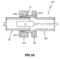
- the heating furnace tube 100 in Fig. 10 is made of the heating furnace tube element on one side 110 made of an ODS ferrous alloy tube and the heating furnace tube element on the other side 120 made of an austenitic heat resistant alloy which are joined via insert metal by diffusion bonding.
- the heating furnace tube element on the other side 120 not only an austenitic heat resistant alloy tube but also an ODS ferrous alloy tube which is the same material as the heating furnace tube element on one side 110 can be used.
- Film M of insert metal is formed on the outer surface of the joint side edge of heating furnace tube element on one side 110 and the joint side edge of the heating furnace tube element on the other side 120 is expanded so as to engage with the joint side edge of the heating furnace tube element on one side 110.
- the joint side edge of the heating furnace tube element on one side 110 is engaged with the joint side edge of the heating furnace tube element on the other side 120 first, then the tightener 140 of which the inner surface has the tapered surface 140t is attached to the tapered surface 120t of the heating furnace tube element on the other side 120, and a stopper block 141 is attached to the section 120f of the heating furnace tube element on the other side 120 where the diameter increases.
- the joint side edge of the heating furnace tube element on the other side 120 is contacted with pressure to the joint side edge of the heating furnace tube element on one side 110 sandwiching the plate layer M of the insert metal, then diffusion bonding is progressed by exhausting, increasing temperature, and by holding the high temperature, in the same manner as the manufacturing process of the above mentioned heating furnace tube 1', and the tube is cooled down to room temperature after diffusion jointing completes, then the tightener 140 and the stopper block 141 are removed and the manufacturing process of the heating furnace tube 100 ends.
- the film M of the insert metal can be formed not only on the heating furnace tube element on one side 110 but also on the inner surface of the heating furnace tube element on the other side 120, and can be formed only on the heating furnace tube element on the other side 120.
- the heating furnace tube 100 with the above mentioned configuration also generates an effect equivalent to the above mentioned heating furnace tube 1'.
- the heating furnace tube 200 in Fig. 11 is made of the heating furnace tube element on one side 210 made of an ODS ferrous alloy tube and the heating furnace tube element on the other side 220 made of an austenitic heat resistant alloy tube which are joined via insert metal by diffusion bonding.
- the heating furnace tube element on the other side 220 not only an austenitic heat resistant alloy tube but also an ODS ferrous alloy tube which is the same material as the heating furnace tube element on one side 210 can be used.
- a male screw 210S is on the joint side edge of the heating furnace tube element on one side 210 and a female screw 220S is on the heating furnace tube element on the other side 220, and film M of the insert metal is formed on the outer surface of the joint side edge of the heating furnace tube element on one side 210 for the entire joining surface with the heating furnace tube element on the other side 220, by electroplating.
- the male screw 210S on the heating furnace tube element on one side 210 and the female screw 220S on the heating furnace tube element on the other side 220 are screwed together to mechanically join each heating furnace tube element 210 and 220, and the joint side edges of the heating furnace tube elements 210 and 220 are contacted with pressure sandwiching the plate layer M of the insert metal, then diffusion bonding is progressed by exhausting, increasing temperature, and holding the high temperature, in the same matter as the manufacturing process of the above mentioned heating furnace tube 1', then the tube is cooled down to room temperature after diffusion bonding completes, and the manufacturing process of the heating furnace tube 200 ends.
- the film M of the insert metal M can be formed not only on the heating furnace tube element on one side 210 but also on the heating furnace tube element on the other side 220, and can be formed only on the heating furnace tube element on the other side 220.
- the female screw can be on the heating furnace tube element on one side 210, and the male screw on the heating furnace tube element on the other side 220.
- a circular insert ring made of insert metal can be attached at the joint sections a and b of each one of the heating furnace tube elements 210 and 220.
- the heating furnace tube 200 with the above mentioned configuration also generates an effect equivalent to the above mentioned heating furnace tube 1'.
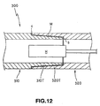
- the heating furnace tube 300 in Fig. 12 is made of the heating furnace tube element on one side 310 made of an ODS ferrous alloy tube and the heating furnace tube element on the other side 320 made of an austenitic heat resistant alloy tube which are joined via insert metal by diffusion bonding.
- the heating furnace tube element on the other side 320 not only an austenitic heat resistant alloy tube but also an ODS ferrous alloy tube which is the same material as the heating furnace tube element on one side 310 can be used.
- a tapered shaped convex engaging section 310T is on the joint side edge of the heating furnace tube element on one side 310
- a tapered shaped concave engaging section 320T is on the joint side edge of the heating furnace tube element on the other side 320
- film M of insert metal is formed on the outer surface of the joint side edge of the heating furnace tube element on one side 310, for the entire joining surface with the heating furnace tube element on the other side 320 by electroplating
- the convex engaging section 310T on the heating furnace tube element on one side 310 and the concave engaging section 320T on the heating furnace tube element on the other side 320 are engaged to mechanically join each one of the heating furnace tube element 310 and 320, and the joint side edges of the heating furnace tube elements 310 and 320 are contact with pressure sandwiching the plate layer M of insert metal by applying 0.1 kg / mm 2 or more compression stress in the tube axis direction of each heating furnace tube element 310 and 320.
- diffusion bonding is progressed by exhausting, increasing temperature and holding the temperature in the same manner as the manufacturing process of the above mentioned heating furnace tube 1', then the tube is cooled down to room temperature after diffusion bonding completes, and the manufacturing process of the heating furnace tube 300 ends.
- the film M of insert metal can be formed not only on the heating furnace tube element on one side 310 but also on the heating furnace tube element on the other side 320, and can be formed only on the heating furnace tube element on the other side 320.
- the concave engaging section can be on the heating furnace tube element on one side 310, and the convex engaging section can be on the heating furnace tube element on the other side 320.
- a circular insert ring made of insert metal can be attached at the joint sections a and b of each one of the heating furnace tube elements 310 and 320.
- the heating furnace tube 300 with the above mentioned configuration also generates an effect equivalent to the above mentioned heating furnace tube 1'.
- the film M of insert metal used in each one of the above mentioned embodiments is formed by electroplating, but wet plating, dry plating, electroless plating, physical deposition (e.g. vacuum deposition, sputtering, ion plating) and vapor plating, including chemical deposition (e.g. high temperature CVD, plasma CVD), spraying and coating metal paste and other methods can be used to form the film M of insert metal.
- physical deposition e.g. vacuum deposition, sputtering, ion plating
- vapor plating including chemical deposition (e.g. high temperature CVD, plasma CVD), spraying and coating metal paste and other methods can be used to form the film M of insert metal.
- the method of manufacturing the heating furnace tube related to the present invention can be effectively applied not only to the cracking tubes of an ethylene plant but also to various heating furnace tubes which are subject to carburization problems, such as CCR plant in a petroleum refining plant.
- a method of manufacturing a heating furnace tube related to the present invention can be effectively applied to heating furnace tubes which are subject to coking and carburization problems.
Landscapes
- Engineering & Computer Science (AREA)
- Mechanical Engineering (AREA)
- Chemical & Material Sciences (AREA)
- General Engineering & Computer Science (AREA)
- Organic Chemistry (AREA)
- Materials Engineering (AREA)
- Metallurgy (AREA)
- Oil, Petroleum & Natural Gas (AREA)
- Physics & Mathematics (AREA)
- General Chemical & Material Sciences (AREA)
- Chemical Kinetics & Catalysis (AREA)
- Thermal Sciences (AREA)
- Production Of Liquid Hydrocarbon Mixture For Refining Petroleum (AREA)
- Pressure Welding/Diffusion-Bonding (AREA)
- Heat Treatment Of Articles (AREA)
Claims (2)
- Verfahren zur Herstellung eines Heizofenrohrs (1), das ein Heizofenrohr-Element (10) umfasst, das aus mit Seltenerdoxiddispersion verstärkter Eisenlegierung hergestellt ist, die 17 - 26 Gew.-% Cr und 2 - 6 Gew.-% Al enthält; und noch ein Heizofenrohr-Element (20) umfasst, das aus der mit Seltenerdoxiddispersion verstärkten Eisenlegierung oder hitzebeständiger Legierung hergestellt ist, die durch Diffusionsbindung über ein Einlagemetall (M) verbunden sind, wobei das Verfahren zur Herstellung des Heizofenrohrs die Schritte umfasst:wobei das Zwischenelement (30) ein Kupplungsansatzrohr (30) ist, an das die Seitenstoßkante des einen Heizofenrohr-Elementes (10) und die Seitenstoßkante des anderen Heizofenrohr-Elementes (20) angesetzt werden, und das eine Heizofenrohr-Element (10) und das andere Heizofenrohr-Element (20) über das Kupplungsansatzrohr (30) verbunden werden, indem eine Diffusionsbindung in dem Stadium durchgeführt wird, wo die Seitenstoßkanten des einen Heizofenrohr-Elementes (10) und des anderen Heizofenrohr-Elementes (20) und das Kupplungsansatzrohr (30) durch ein Druckbelüftungsmittel (P) über das zwischen den Seitenstoßkanten des einen Heizofenrohr-Elementes (10), des anderen Heizofenrohr-Elementes (20) und dem Kupplungsansatzrohr (30) angeordnete Einlagemetall (M) unter Druck in Kontakt gebracht werden, wobei das Druckbelüftungsmittel (P) einen Spanner (40, 41) mit Schrägflächen (40t, 41t) umfasst, der mit der Schrägfläche (40t, 41t) in Eingriff geht und das Kupplungsansatzrohr (30) an Schrägflächen (30t) in Radiusrichtung berührt.Anformen oder Ansetzen des Einlagemetalls (M) an zumindest eine der Seitenstoßkanten des einen Heizofenrohr-Elementes (10) und des anderen Heizofenrohr-Elementes (20);Druckkontaktieren der Seitenstoßkante des einen Heizofenrohr-Elementes (10) mit der Seitenstoßkante des anderen Heizofenrohr-Elementes (20) über ein Zwischenelement (30); undDiffusionsverbinden des einen Heizofenrohr-Elementes (10) und des anderen Heizofenrohr-Elementes (20) durch Erwärmen des Einlagemetalls (M),
- Verfahren zur Herstellung des Heizofenrohrs gemäß Anspruch 1, dadurch gekennzeichnet, dass das Einlagemetall (M) durch Plattieren geformt wird.
Priority Applications (1)
| Application Number | Priority Date | Filing Date | Title |
|---|---|---|---|
| EP05014959A EP1600519A1 (de) | 1997-08-20 | 1998-08-19 | Heizofenrohr bestehend aus Stahllegierung mit Seltenerdoxiden, sowie Verfahren zu dessen Nutzung |
Applications Claiming Priority (5)
| Application Number | Priority Date | Filing Date | Title |
|---|---|---|---|
| JP22387397 | 1997-08-20 | ||
| JP22387397A JP4281881B2 (ja) | 1997-08-20 | 1997-08-20 | 加熱炉管および加熱炉管の製造方法 |
| JP1142298 | 1998-01-23 | ||
| JP1142298A JPH11209850A (ja) | 1998-01-23 | 1998-01-23 | 加熱炉管および加熱炉管の使用方法 |
| PCT/JP1998/003673 WO1999009230A1 (en) | 1997-08-20 | 1998-08-19 | Heating furnace tube, method of using the same, and method of manufacturing the same |
Related Child Applications (1)
| Application Number | Title | Priority Date | Filing Date |
|---|---|---|---|
| EP05014959A Division EP1600519A1 (de) | 1997-08-20 | 1998-08-19 | Heizofenrohr bestehend aus Stahllegierung mit Seltenerdoxiden, sowie Verfahren zu dessen Nutzung |
Publications (3)
| Publication Number | Publication Date |
|---|---|
| EP1018563A1 EP1018563A1 (de) | 2000-07-12 |
| EP1018563A4 EP1018563A4 (de) | 2001-12-12 |
| EP1018563B1 true EP1018563B1 (de) | 2005-11-02 |
Family
ID=26346837
Family Applications (2)
| Application Number | Title | Priority Date | Filing Date |
|---|---|---|---|
| EP98938895A Expired - Lifetime EP1018563B1 (de) | 1997-08-20 | 1998-08-19 | Verfahren zur herstellung eines heizofenrohres mit einem zwischenelement |
| EP05014959A Withdrawn EP1600519A1 (de) | 1997-08-20 | 1998-08-19 | Heizofenrohr bestehend aus Stahllegierung mit Seltenerdoxiden, sowie Verfahren zu dessen Nutzung |
Family Applications After (1)
| Application Number | Title | Priority Date | Filing Date |
|---|---|---|---|
| EP05014959A Withdrawn EP1600519A1 (de) | 1997-08-20 | 1998-08-19 | Heizofenrohr bestehend aus Stahllegierung mit Seltenerdoxiden, sowie Verfahren zu dessen Nutzung |
Country Status (11)
| Country | Link |
|---|---|
| US (1) | US6514631B1 (de) |
| EP (2) | EP1018563B1 (de) |
| KR (1) | KR100509290B1 (de) |
| CN (1) | CN1085741C (de) |
| AU (1) | AU733795C (de) |
| BR (1) | BR9815655A (de) |
| DE (1) | DE69832190T2 (de) |
| ID (1) | ID24490A (de) |
| RU (1) | RU2205247C2 (de) |
| TW (1) | TW548334B (de) |
| WO (1) | WO1999009230A1 (de) |
Cited By (1)
| Publication number | Priority date | Publication date | Assignee | Title |
|---|---|---|---|---|
| AU2007290757B2 (en) * | 2006-08-25 | 2011-05-26 | Exxonmobil Chemical Patents Inc. | Production of aromatics from methane |
Families Citing this family (41)
| Publication number | Priority date | Publication date | Assignee | Title |
|---|---|---|---|---|
| EP1268115B1 (de) * | 2000-03-29 | 2010-03-31 | Shell Internationale Researchmaatschappij B.V. | Verfahren und vorrichtung zum verbinden von rohrförmigen elementen für die erdölindustrie |
| US6913842B2 (en) * | 2000-05-18 | 2005-07-05 | Fukuju Industry Corporation Ltd. | Liquid phase diffusion welded metal-made precision machine component and production method thereof |
| EP1167852A3 (de) * | 2000-05-18 | 2003-11-12 | Daido Tokushuko Kabushiki Kaisha | Diffusionsgebundenes Metallrohr, Rohrexpansionsmethode für diffusionsgebundenes Metallrohr und Verfahren zur Inspektion von diffusionsgebunden Metallrohren |
| TW494201B (en) * | 2001-08-08 | 2002-07-11 | Jgc Corp | Connection method and structure for pipe with poor weldability for high temperature application |
| US6749518B2 (en) * | 2002-04-08 | 2004-06-15 | General Electric Company | Inertia welded shaft and method therefor |
| DE10237763B4 (de) * | 2002-08-17 | 2006-01-12 | Schott Ag | Verfahren zur Herstellung unlösbarer stoffschlüssiger Verbindungen von Bauteilen aus oxid-dispergierten-(ODS)-metallischen Werkstoffen durch Verschweißen und durch das Verfahren hergestellte Bauteile |
| US7482502B2 (en) * | 2003-01-24 | 2009-01-27 | Stone & Webster Process Technology, Inc. | Process for cracking hydrocarbons using improved furnace reactor tubes |
| SE524010C2 (sv) * | 2003-05-20 | 2004-06-15 | Sandvik Ab | Strålningsrör i krackerugn |
| JP4540392B2 (ja) * | 2003-06-02 | 2010-09-08 | 新日本製鐵株式会社 | 金属機械部品の液相拡散接合方法 |
| EP1486282A1 (de) * | 2003-06-04 | 2004-12-15 | Delphi Technologies, Inc. | Verfahren und Vorrichtung zur Herstellung von metallischen Bauteilen und entsprechendes Bauteil |
| US7048041B2 (en) | 2003-07-25 | 2006-05-23 | Stone & Webster Process Technology, Inc. | Systems and apparatuses for stabilizing reactor furnace tubes |
| US6886736B1 (en) * | 2003-10-07 | 2005-05-03 | Veniamin V. Gubarev | Method of diffusion welding of different metals in air |
| US7451657B2 (en) * | 2004-01-16 | 2008-11-18 | Jentek Sensors, Inc. | Material condition monitoring with multiple sensing modes |
| IL161011A (en) * | 2004-03-22 | 2006-12-10 | E E R Env Energy Resrc Israel | Apparatus and system for controlling the level of potential pollutants in a waste treatment plant |
| SE528189C2 (sv) | 2004-12-21 | 2006-09-19 | Sandvik Intellectual Property | Förfarande samt rörfog för hopfogning av komponenter som innefattar eller är gjort av ett material som är svårt att svetsa |
| US8138384B2 (en) * | 2004-12-22 | 2012-03-20 | Exxonmobil Chemical Patents Inc. | Production of alkylated aromatic hydrocarbons from methane |
| SE529741C2 (sv) * | 2005-01-17 | 2007-11-13 | Sandvik Intellectual Property | Förfarande för termisk isolering av svetsfog samt hylsa därför |
| SE529444C2 (sv) * | 2005-12-02 | 2007-08-14 | Sandvik Intellectual Property | Rör och användning av röret |
| MY148625A (en) | 2006-08-18 | 2013-05-15 | Porex Corp | Sintered polymeric materials and applications thereof |
| US20090250442A1 (en) * | 2007-12-03 | 2009-10-08 | Eerc Foundation | Joining of difficult-to-weld materials |
| US20090252637A1 (en) * | 2007-12-03 | 2009-10-08 | Energy & Environmental Research Center Foundation | Joining of difficult-to-weld materials and sintering of powders using a low-temperature vaporization material |
| US8450552B2 (en) | 2009-05-18 | 2013-05-28 | Exxonmobil Chemical Patents Inc. | Pyrolysis reactor materials and methods |
| US9011620B2 (en) | 2009-09-11 | 2015-04-21 | Technip Process Technology, Inc. | Double transition joint for the joining of ceramics to metals |
| EP2305453A1 (de) * | 2009-09-30 | 2011-04-06 | Logstor A/S | Verbessertes Wasserstoppverfahren in einzelnen isolierten Leitungen |
| EP2501783A2 (de) * | 2009-11-20 | 2012-09-26 | ExxonMobil Chemical Patents Inc. | Poröse pyrolysereaktormaterialien und verfahren |
| US8932534B2 (en) | 2009-11-20 | 2015-01-13 | Exxonmobil Chemical Patents Inc. | Porous pyrolysis reactor materials and methods |
| DE102010011170A1 (de) * | 2010-03-12 | 2011-09-15 | Sms Siemag Ag | Düsenkopf für eine Blaslanze |
| US20150014989A1 (en) | 2012-02-23 | 2015-01-15 | Shell Oil Company | Connector assembly |
| WO2013186400A2 (en) * | 2012-06-15 | 2013-12-19 | Shell Internationale Research Maatschappij B.V. | Method and connector assembly for connecting tubular members |
| US8926176B2 (en) * | 2012-07-31 | 2015-01-06 | Pgi International, Ltd. | Modular thermowell and method |
| WO2014095836A1 (en) | 2012-12-20 | 2014-06-26 | Shell Internationale Research Maatschappij B.V. | Pipe connector and method |
| JP6302754B2 (ja) | 2014-06-04 | 2018-03-28 | オリンパス株式会社 | 接合構造及び生検針 |
| EP3224519B1 (de) * | 2014-11-28 | 2025-07-23 | General Electric Technology GmbH | Fluidleitungselement und verfahren zur herstellung des fluidleitungselements |
| WO2018115503A1 (en) * | 2016-12-23 | 2018-06-28 | Sandvik Intellectual Property Ab | A lance tube |
| CN108436392B (zh) * | 2018-03-15 | 2019-07-09 | 江苏九众九自动化科技有限公司 | 缩颈模热镶硬质合金制作工艺 |
| CN109442998B (zh) * | 2018-11-06 | 2020-03-24 | 长兴创智科技有限公司 | 一种炉管 |
| KR20220017422A (ko) * | 2019-06-05 | 2022-02-11 | 비를라 카본 유.에스.에이., 인코포레이티드 | 고온의 카본 블랙 공기 예열기(high temperature carbon black air preheater) |
| CN110712014A (zh) * | 2019-11-21 | 2020-01-21 | 安徽亚太锚链制造有限公司 | 一种海船用锚链的生产工艺 |
| US11668414B2 (en) * | 2019-12-12 | 2023-06-06 | Lc Advanced Motor Technology Corporation | Dual metal adapter |
| EP3933012A1 (de) * | 2020-06-29 | 2022-01-05 | Dow Global Technologies LLC | Verfahren zur verringerung der bildung von schwefelkohlenstoff in dampfcrackverfahren zur herstellung von olefinen |
| CN113199172A (zh) * | 2021-05-06 | 2021-08-03 | 深圳市镱豪金属有限公司 | 一种自动焊锡生产线 |
Family Cites Families (18)
| Publication number | Priority date | Publication date | Assignee | Title |
|---|---|---|---|---|
| US3027252A (en) * | 1959-09-29 | 1962-03-27 | Gen Electric | Oxidation resistant iron-chromium alloy |
| BE795663A (fr) * | 1972-03-20 | 1973-06-18 | United Aircraft Corp | Feuille intermediaire pour soudures par diffusion |
| US4059217A (en) * | 1975-12-30 | 1977-11-22 | Rohr Industries, Incorporated | Superalloy liquid interface diffusion bonding |
| SU629243A1 (ru) * | 1977-05-19 | 1978-10-25 | Всесоюзный Заочный Политехнический Институт | Жаростойка сталь |
| US4402746A (en) * | 1982-03-31 | 1983-09-06 | Exxon Research And Engineering Co. | Alumina-yttria mixed oxides in dispersion strengthened high temperature alloys |
| US4414023A (en) * | 1982-04-12 | 1983-11-08 | Allegheny Ludlum Steel Corporation | Iron-chromium-aluminum alloy and article and method therefor |
| JPS5939488A (ja) * | 1982-08-31 | 1984-03-03 | Mitsubishi Heavy Ind Ltd | 管状製品の拡散接合方法 |
| AU600009B2 (en) * | 1986-08-18 | 1990-08-02 | Inco Alloys International Inc. | Dispersion strengthened alloy |
| SE459524B (sv) * | 1987-12-04 | 1989-07-10 | Kanthal Ab | Vaermestraalningsroer |
| JPH0627306B2 (ja) * | 1988-12-08 | 1994-04-13 | 住友金属工業株式会社 | エチレン分解炉管用耐熱鋼 |
| JPH02213449A (ja) | 1989-02-13 | 1990-08-24 | Sumitomo Metal Ind Ltd | ごみ焼却廃熱ボイラ管用高耐食鋼 |
| US5118028A (en) * | 1989-08-29 | 1992-06-02 | Sumitomo Metal Industries, Ltd. | Diffusion bonding method for corrosion-resistant materials |
| SE469754B (sv) * | 1990-05-14 | 1993-09-06 | Kanthal Ab | Ugn foer krackning av kolvaeten |
| JPH0475773A (ja) * | 1990-07-18 | 1992-03-10 | Daido Steel Co Ltd | 金属管の拡散接合方法および挿入材 |
| JPH04147947A (ja) * | 1990-10-09 | 1992-05-21 | Daido Steel Co Ltd | 酸化物分散強化型Fe基合金とその製造方法 |
| JPH04147945A (ja) * | 1990-10-11 | 1992-05-21 | Nisshin Steel Co Ltd | 耐高温酸化性および靭性に優れた高Al含有フェライト系ステンレス鋼 |
| FR2691377B1 (fr) * | 1992-05-21 | 1995-04-14 | Inst Francais Du Petrole | Four tournant pour réaction chimique. |
| JPH07166290A (ja) * | 1993-12-16 | 1995-06-27 | Kubota Corp | 耐浸炭性及び耐酸化性にすぐれる耐熱合金 |
-
1998
- 1998-08-18 TW TW087113539A patent/TW548334B/zh not_active IP Right Cessation
- 1998-08-19 WO PCT/JP1998/003673 patent/WO1999009230A1/ja not_active Ceased
- 1998-08-19 US US09/485,871 patent/US6514631B1/en not_active Expired - Fee Related
- 1998-08-19 RU RU2000106524/02A patent/RU2205247C2/ru not_active IP Right Cessation
- 1998-08-19 AU AU87472/98A patent/AU733795C/en not_active Ceased
- 1998-08-19 CN CN98808314A patent/CN1085741C/zh not_active Expired - Fee Related
- 1998-08-19 EP EP98938895A patent/EP1018563B1/de not_active Expired - Lifetime
- 1998-08-19 EP EP05014959A patent/EP1600519A1/de not_active Withdrawn
- 1998-08-19 ID IDW20000323A patent/ID24490A/id unknown
- 1998-08-19 BR BR9815655-1A patent/BR9815655A/pt not_active Application Discontinuation
- 1998-08-19 KR KR10-2000-7001740A patent/KR100509290B1/ko not_active Expired - Fee Related
- 1998-08-19 DE DE69832190T patent/DE69832190T2/de not_active Expired - Fee Related
Cited By (1)
| Publication number | Priority date | Publication date | Assignee | Title |
|---|---|---|---|---|
| AU2007290757B2 (en) * | 2006-08-25 | 2011-05-26 | Exxonmobil Chemical Patents Inc. | Production of aromatics from methane |
Also Published As
| Publication number | Publication date |
|---|---|
| CN1085741C (zh) | 2002-05-29 |
| EP1018563A1 (de) | 2000-07-12 |
| DE69832190D1 (de) | 2005-12-08 |
| DE69832190T2 (de) | 2006-06-01 |
| ID24490A (id) | 2000-07-20 |
| CN1267340A (zh) | 2000-09-20 |
| KR100509290B1 (ko) | 2005-08-18 |
| WO1999009230A1 (en) | 1999-02-25 |
| AU733795B2 (en) | 2001-05-24 |
| AU733795C (en) | 2002-02-07 |
| BR9815655A (pt) | 2001-01-30 |
| TW548334B (en) | 2003-08-21 |
| RU2205247C2 (ru) | 2003-05-27 |
| KR20010023118A (ko) | 2001-03-26 |
| EP1600519A1 (de) | 2005-11-30 |
| AU8747298A (en) | 1999-03-08 |
| US6514631B1 (en) | 2003-02-04 |
| EP1018563A4 (de) | 2001-12-12 |
Similar Documents
| Publication | Publication Date | Title |
|---|---|---|
| EP1018563B1 (de) | Verfahren zur herstellung eines heizofenrohres mit einem zwischenelement | |
| US7169480B2 (en) | Clad pipe | |
| EP1043084B1 (de) | Verfahren zum Herstellen von hitzbeständigen metallischen Rohren und hergestellte Rohre | |
| EP1164180A2 (de) | Anti-Verkokungs,hitzebeständige Mehrschichtmetallrohre und Verfahren zu ihrer Herstellung | |
| KR20120027284A (ko) | 비정질 코팅의 표면 처리 | |
| EP2094431A2 (de) | Lötmaterial | |
| JP2013208650A (ja) | ろう付け材料、ろう付け方法、ろう付けされた物品、および該ろう付け材料を含むペースト | |
| KR20180133506A (ko) | 튜브 및 튜브 제조 방법 | |
| WO2000050663A1 (en) | Diffusion method for coating high temperature nickel chromium alloy products | |
| WO2012024074A1 (en) | Bi-metal spiral wound gasket | |
| RU2711168C2 (ru) | Способ изготовления трубного устройства, трубное устройство и печь, снабженная таким трубным устройством | |
| CN114505656A (zh) | 柱塞泵壳体的制作工艺、柱塞泵壳体及柱塞泵 | |
| FR3064039A1 (fr) | Procede de chemisage d'une conduite en acier pour le transport sous-marin de fluides | |
| CN100436908C (zh) | 复合管 | |
| CA2702863A1 (fr) | Tube a surface interne augmentee utilise dans des fours, procede de fabrication et applications | |
| EP0688889B1 (de) | Verfahren zur Passivierung von Werkstücken aus Eisen-Nickelbasis-Superlegierungen | |
| JP4608724B2 (ja) | 耐コーキング性にすぐれた耐熱多層金属管とその製造方法 | |
| Voiculescu | Brazing behaviour of Ag-Cu filler materials | |
| MXPA00001775A (en) | Heating furnace tube, method of using the same, and method of manufacturing the same | |
| EP3144505B1 (de) | Gasturbinenbauteil und verfahren zur herstellung | |
| US20240351134A1 (en) | Method for friction-joining galvanized steel sheets, and joined structure | |
| EP4440769B1 (de) | Verfahren zur herstellung einer doppelschichtigen wärmetauscherwand | |
| MX2014015399A (es) | Sistema de creacion de materiales de recubrimiento utilizando soldadura de union de resistencia. | |
| JP2001098390A (ja) | 内面の耐食性に優れた溶接管及びその製造方法 | |
| JP4268310B2 (ja) | 耐硫化割れ性に優れた接合体およびその製造方法 |
Legal Events
| Date | Code | Title | Description |
|---|---|---|---|
| PUAI | Public reference made under article 153(3) epc to a published international application that has entered the european phase |
Free format text: ORIGINAL CODE: 0009012 |
|
| 17P | Request for examination filed |
Effective date: 20000317 |
|
| AK | Designated contracting states |
Kind code of ref document: A1 Designated state(s): DE FR GB IT NL |
|
| A4 | Supplementary search report drawn up and despatched |
Effective date: 20011030 |
|
| AK | Designated contracting states |
Kind code of ref document: A4 Designated state(s): DE FR GB IT NL |
|
| RIC1 | Information provided on ipc code assigned before grant |
Free format text: 7C 22C 38/00 A, 7C 22C 38/18 B, 7B 23K 20/00 B, 7C 07C 4/04 B, 7C 10G 9/16 B, 7B 23K 20/02 B, 7B 23K 20/16 B, 7C 10G 9/20 B |
|
| 17Q | First examination report despatched |
Effective date: 20020704 |
|
| GRAP | Despatch of communication of intention to grant a patent |
Free format text: ORIGINAL CODE: EPIDOSNIGR1 |
|
| RTI1 | Title (correction) |
Free format text: METHOD OF MANUFACTURING A HEATING FURNACE TUBE WITH AN INTERMEDIATE ELEMENT |
|
| GRAS | Grant fee paid |
Free format text: ORIGINAL CODE: EPIDOSNIGR3 |
|
| GRAA | (expected) grant |
Free format text: ORIGINAL CODE: 0009210 |
|
| AK | Designated contracting states |
Kind code of ref document: B1 Designated state(s): DE FR GB IT NL |
|
| PG25 | Lapsed in a contracting state [announced via postgrant information from national office to epo] |
Ref country code: IT Free format text: LAPSE BECAUSE OF FAILURE TO SUBMIT A TRANSLATION OF THE DESCRIPTION OR TO PAY THE FEE WITHIN THE PRESCRIBED TIME-LIMIT;WARNING: LAPSES OF ITALIAN PATENTS WITH EFFECTIVE DATE BEFORE 2007 MAY HAVE OCCURRED AT ANY TIME BEFORE 2007. THE CORRECT EFFECTIVE DATE MAY BE DIFFERENT FROM THE ONE RECORDED. Effective date: 20051102 |
|
| REG | Reference to a national code |
Ref country code: GB Ref legal event code: FG4D |
|
| REF | Corresponds to: |
Ref document number: 69832190 Country of ref document: DE Date of ref document: 20051208 Kind code of ref document: P |
|
| ET | Fr: translation filed | ||
| PLBE | No opposition filed within time limit |
Free format text: ORIGINAL CODE: 0009261 |
|
| STAA | Information on the status of an ep patent application or granted ep patent |
Free format text: STATUS: NO OPPOSITION FILED WITHIN TIME LIMIT |
|
| 26N | No opposition filed |
Effective date: 20060803 |
|
| PGFP | Annual fee paid to national office [announced via postgrant information from national office to epo] |
Ref country code: NL Payment date: 20080815 Year of fee payment: 11 Ref country code: DE Payment date: 20080905 Year of fee payment: 11 |
|
| PGFP | Annual fee paid to national office [announced via postgrant information from national office to epo] |
Ref country code: FR Payment date: 20080818 Year of fee payment: 11 |
|
| PGFP | Annual fee paid to national office [announced via postgrant information from national office to epo] |
Ref country code: GB Payment date: 20080827 Year of fee payment: 11 |
|
| REG | Reference to a national code |
Ref country code: NL Ref legal event code: V1 Effective date: 20100301 |
|
| GBPC | Gb: european patent ceased through non-payment of renewal fee |
Effective date: 20090819 |
|
| REG | Reference to a national code |
Ref country code: FR Ref legal event code: ST Effective date: 20100430 |
|
| PG25 | Lapsed in a contracting state [announced via postgrant information from national office to epo] |
Ref country code: NL Free format text: LAPSE BECAUSE OF NON-PAYMENT OF DUE FEES Effective date: 20100301 Ref country code: FR Free format text: LAPSE BECAUSE OF NON-PAYMENT OF DUE FEES Effective date: 20090831 Ref country code: DE Free format text: LAPSE BECAUSE OF NON-PAYMENT OF DUE FEES Effective date: 20100302 |
|
| PG25 | Lapsed in a contracting state [announced via postgrant information from national office to epo] |
Ref country code: GB Free format text: LAPSE BECAUSE OF NON-PAYMENT OF DUE FEES Effective date: 20090819 |