EP1016766A1 - Cadres et structure composée par ces cadres - Google Patents
Cadres et structure composée par ces cadres Download PDFInfo
- Publication number
- EP1016766A1 EP1016766A1 EP98310780A EP98310780A EP1016766A1 EP 1016766 A1 EP1016766 A1 EP 1016766A1 EP 98310780 A EP98310780 A EP 98310780A EP 98310780 A EP98310780 A EP 98310780A EP 1016766 A1 EP1016766 A1 EP 1016766A1
- Authority
- EP
- European Patent Office
- Prior art keywords
- frame
- support
- lateral
- connector
- members
- Prior art date
- Legal status (The legal status is an assumption and is not a legal conclusion. Google has not performed a legal analysis and makes no representation as to the accuracy of the status listed.)
- Withdrawn
Links
Images


Classifications
-
- E—FIXED CONSTRUCTIONS
- E04—BUILDING
- E04G—SCAFFOLDING; FORMS; SHUTTERING; BUILDING IMPLEMENTS OR AIDS, OR THEIR USE; HANDLING BUILDING MATERIALS ON THE SITE; REPAIRING, BREAKING-UP OR OTHER WORK ON EXISTING BUILDINGS
- E04G1/00—Scaffolds primarily resting on the ground
- E04G1/14—Comprising essentially pre-assembled two-dimensional frame-like elements, e.g. of rods in L- or H-shape, with or without bracing
-
- E—FIXED CONSTRUCTIONS
- E04—BUILDING
- E04G—SCAFFOLDING; FORMS; SHUTTERING; BUILDING IMPLEMENTS OR AIDS, OR THEIR USE; HANDLING BUILDING MATERIALS ON THE SITE; REPAIRING, BREAKING-UP OR OTHER WORK ON EXISTING BUILDINGS
- E04G1/00—Scaffolds primarily resting on the ground
- E04G1/02—Scaffolds primarily resting on the ground composed essentially of members elongated in one dimension only, e.g. poles, lattice masts, with or without end portions of special form, connected together by any means
- E04G1/04—Scaffolds primarily resting on the ground composed essentially of members elongated in one dimension only, e.g. poles, lattice masts, with or without end portions of special form, connected together by any means the members being exclusively poles, rods, beams, or other members of similar form and simple cross-section
Definitions
- the present invention relates to structures such as prefabricated scaffoldings, shorings and support beams, as well as frames used for assembling the structures.
- a prefabricated scaffolding for workers to walk thereon is installed opposedly to the outer side faces of a structure.
- a shoring or a support beam to support heavy objects such as floors and bridge girders during the work.
- Prefabricated scaffoldings, shorings and support beams each employ frames in which support posts are assembled lengthwise and crosswise.
- PAL SUPPORT is used as a frame exclusive for shoring.
- the PAL SUPPORT is constituted by a frame which is triangular in front view and which comprises a single support post, a V-shaped lateral member connected sideways of the support post, and a connector provided at an outer end of the lateral member and having a hole.
- prefabricated scaffoldings and support beams are exclusive frames formed for the respective purposes, they cannot be used in common to all of the structures, that is, they are not versatile and are therefore uneconomical,
- the foregoing PAL SUPPORT is advantageous in that it can be assembled lengthwise and crosswise as a single product. However, when the connector on one support post side is brought into engagement with another support post and when there later arises the necessity of removing or replacing a certain portion during work or after assembly the vertical support posts must once be pulled out, which work is very difficult and troublesome.
- a frame according to the present invention comprises a support post, a first connector support member, mounted at an intermediate or nearly intermediate position of the support post, a second connector support member mounted at an upper or lower position of the support post or at both upper and lower positions of the support post, one or plural lateral members secured sideways to the support post detachably or rotatably, and a connector provided at an outer end of the lateral member in a vertical position corresponding to the height of the first or the second connector support member.
- a prefabricated scaffolding according to the resent invention as constituted by combining a plurality of the above frames lengthwise and crosswise.
- a shoring according to the present invention is constituted by combining a plurality of the above frames lengthwise and crosswise.
- a support beam according to the present invention is constituted by combining a plurality of the above frames lengthwise and crosswise.
- FIGS. 1 to 58 there are illustrated frames and reinforcing support posts embodying the present invention.
- FIGS. 60 to 65 there are illustrated prefabricated scaffoldings assembled by using any of the above frames in accordance with embodiments of the present invention.
- FIGS. 66 to 69 there are illustrated shorings assembled by using any of the above frames in accordance with embodiments of the present invention.
- FIGS. 70 to 73 there are illustrated support beams assembled by using any of the above frames in accordance with embodiments of the present invention.
- FIGS. 74 to 82 there are illustrated support posts, balustrades and reinforcing frames which are used in assembling prefabricated scaffoldings, shorings or support beams.
- FIGS.60, 61 and 62 which scaffoldings are indicated at A, use the frame shown in FIG.41.
- This frame comprises two support posts 1, 1 and a horizontal member 4 or 4b connected rotatably or detachably to one support post 1.
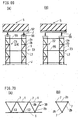
- a plurality of frames 3 are disposed upright in the lateral direction and at two rows in front and in the rear, the frames 3 each comprising two parallel, upright support posts 1, 1, a balustrade 2' mounted laterally between the support posts 1, 1 and a horizontal member 4 as a lateral member secured to one support post.
- the opposed front and rear support posts 1, 1 are detachably interconnected through the horizontal member 4 as a lateral member secured to one support post 1, while the support posts 1, 1 adjacent to each other in the lateral direction are interconnected through two horizontal balustrades 2a as lateral members secured detachably to the right-hand support post 1 in FIG. 60.
- one or plural scaffolding boards 5 are disposed in series in the lateral direction between the front and rear frames 3, 3, and both end portions of each scaffolding board are detachably engaged through engaging portions 6 with the horizontal members 4 corresponding to the said end portions.
- perforated flanges 7 On the outer periphery of each support post 1 are mounted perforated flanges 7 as first and second connector support members at upper, intermediate and lower positions.
- the balustrade 2' comprises two horizontal members which are an upper horizontal member mounted detachably between the upper flanges 7, 7 and a lower horizontal member mounted between adjacent support posts 1, 1, provided the balustrade 2' may be constituted by only the upper or the lower horizontal member.
- horizontal members 4 mounted between the front and rear support posts 1, 1 are detachably connected at both ends thereof respectively to the upper, intermediate and lower flanges 7, provided there may be only one horizontal member or may be two upper and lower horizontal members as shown in the figures.
- balustrades 2a are connected to the support posts 1, 1 through flanges 7 as connector support members, there may be used other connector support members such as, for example, pins.
- Scaffolding boards 5 are arranged in series in the lateral direction and plural such boards are arranged in the front and rear direction, provided a single board may be used in the front and rear direction if the board is wide in the same direction.
- each scaffolding board At both ends of each scaffolding boards are formed engaging portions 6 of C- or L-shaped section. Through the engaging portions 6 the scaffolding board 5 is connected detachably to the intermediate or lower horizontal members 4. In the scaffolding boards 5, 5 adjacent to each other in the lateral direction, the right-hand engaging portion 6 of the left-hand scaffolding board 5 and the left-hand engaging portion 6 of the right-hand scaffolding board 5 are formed in an alternate manner.
- the balustrade 2a comprises two upper and lower horizontal members, right and left vertical support rods connected to end portions of the two horizontal members, and bifurcated metallic pieces 12 as connectors provided at both ends of each horizontal member.
- the two horizontal members may be substituted by a single horizontal member.
- one or plural baseboards 8 are disposed upright and in series laterally on each of both front and rear sides of the scaffolding boards 5. End portions of each baseboard 8 are connected to holes of the flanges 7 detachably through pins.
- a baseboard 9 upright in the front and rear direction, which is connected in the same manner as above.
- the following method is adopted for disposing the prefabricated scaffolding A in an opposed relation to a structure B such as a building.
- a large number of frames 3 are arranged upright laterally in two front and rear rows.
- frames 3 adjacent to each other in the lateral direction are connected together through the balustrade 2a secured detachably to one support post 1, while frames 3, 3 opposed to each other in the front and rear direction are connected together through the horizontal members 4 secured to one support post 1.
- a scaffolding frame which is in the shape of rectangular parallelepiped in plan, in which are then mounted scaffolding boards 5 at intermediate positions to complete the scaffolding board.
- the front and rear frames 3, 3 are to be arranged at symmetric positions or arranged in an alternate fashion. In the latter case, it is the balustrade 2a that is opposed on the rear side to the front frame 3, and a horizontal member is mounted between the right-hand support post 1 of the front frame 3 and the left-hand support post 1 of the rear frame 3.
- the support posts 1 may be raised directly on the ground. Alternatively, support posts may be raised on the ground through jacks and the support posts 1 which constitute each frame 3 may be detachably inserted respectively into the upper ends of the support rods.
- the support posts may be arranged one by one, or a set of two support rods connected through a horizontal support bar may be raised on the ground through jacks. Further, a plurality of frames 3 may be mounted vertically in plural stages. In this case, as shown in FIG. 53, the upper support post 1 is inserted into an upper-end hole of the lower support post 1 through a spigot portion 1a.
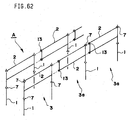
- FIG. 62 schematically illustrates a prefabricated scaffolding according to another embodiment of the present invention.
- This prefabricated scaffolding indicated at A, has been assembled by using, for example, such a frame as shown in FIG. 3 or 9.
- a frame 3a comprises one support post 1 and a balustrade 2 as a lateral member mounted laterally to the support post 1.
- Plural such frames 3a are laterally arranged upright in two front and rear rows. Front and rear support posts 1, 1 opposed to each other are interconnected detachably through the same horizontal members 4 as in FIG. 60, and support posts 1, 1 adjacent to each other laterally are interconnected through the balustrade 2 of one support post 1 and a metallic piece 13 as a connector.
- one or plural scaffolding boards 5 are laterally arranged in series between the front and rear frames 3, 3, and both end portions of each scaffolding board 5 are engaged detachably with the associated horizontal members 4.
- At the leftmost end position of the prefabricated scaffolding A is raised such one support post 1A as shown in FIG. 75, or as illustrated in FIG. 62, the same frame as the frame 3 in FIG. 60 is raised on the ground.
- balustrade 2 In the case where one frame 3a comprising a single support post 1 and the balustrade 2 mounted at the upper portion of the support post 1 is to be connected to another like frame 3a, an end portion of the balustrade 2 is connected detachably to the support post of the frame 3a adjacent laterally to the one frame.
- the balustrade 2 comprises one or two parallel horizontal members, and one end of the balustrade 2 is connected to the support post 1 through a flange 7 or by welding or through a pin or the like.
- a metallic piece 13 At the opposite end of the balustrade 2 is formed a metallic piece 13 as a connector, which is connected to a flange 7 on the other adjacent support post 1 side.
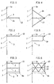
- the frames shown in FIGS. 1 to 18 belong to the same group and are common to one another in that one or plural horizontal members as lateral members are disposed horizontally with respect to one support post.
- the frames 3 in question each comprise one support post 1, a flange 7 as a first connector support member provided at an intermediate position of the support post 1, a flange 7 as a second connector support member provided at an upper position of the support post 1, a horizontal member as a lateral member connected to the intermediate or the upper flange 7, and a metallic piece 13 as a connector disposed at an outer end of the horizontal member in a corresponding relation to the associated flange 7.
- the frame 3 shown in FIG.1 comprises a support post 1, flanges 7, 7 provided at intermediate and upper positions, respectively, of the support post 1, a horizontal member 2a connected at a base end thereof to the intermediate flange 7, and a metallic piece 13 provided at an outer end of the horizontal member 2a, the metallic piece 13 comprising a bifurcated shoe and a wedge.
- a spigot portion 1a of a small diameter At an upper end of the support post 1 is formed a spigot portion 1a of a small diameter.
- Other constructional points are the same as in the frame of FIG. 1.
- two upper and lower horizontal members 2, 2 are connected respectively to an upper flange 7 and an outer surface of a support post 1
- a horizontal baseboard 8 is connected to an intermediate flange 7
- the two horizontal members 2, 2 and the baseboard 8 are connected together at their outer ends through a vertical support rod
- a metallic piece 13 is provided at the outer end of the upper horizontal member 2
- a pin 8a is provided at the outer end of the baseboard 8.
- a base end of a horizontal member L3 as a lateral member is connected to an intermediate flange 7
- a metallic piece 13 is provided at an outer end of the horizontal member L3
- two upper and lower diagonal members 2b, 2b as lateral members are mounted between outer surfaces at upper and lower positions of a support post 1 and the outer end of the horizontal member L3.
- a U-shaped lateral member comprising a horizontal member 2 and an L-shaped member 2e is connected to a support post 1.
- base ends of the horizontal member 2 and the L-shaped member 2e are connected respectively to an upper flange 7 and an outer surface of the support post 1, and a metallic piece 13 is provided at an outer end of the horizontal member 2.
- reinforcing diagonal members 22, 22 are mounted in X shape in plan.
- a reinforcing diagonal member 19 is mounted between the intermediate flange 7 and the outer end of the horizontal member 2.
- a horizontal reinforcing member H12 is mounted between the support post 1 and a diagonal member 2d.
- horizontal members 2a, 2a as lateral members, which serve also as balustrades, are connected at their base ends to an upper flange 7 and an intermediate flange 7, respectively, and metallic pieces 13, 13 are provided respectively at outer ends of the horizontal members 2a, 2a.
- a horizontal reinforcing member 2f for reinforcing the horizontal members 2a, 2a and a vertical support rod 2g are used as additional components.
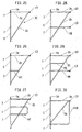
- FIG. 11 In the frame of FIG. 11, indicated at 3A, two upper and lower flanges 7, 7 and an intermediate flange 7 are formed on a support post 1, horizontal members 2a, 2a1 as lateral members are respectively connected at their base ends to the flanges 7, outer ends of the horizontal members are connected together through a vertical support rod, and metallic pieces 13, 13 associated with the flanges 7 are provided respectively at the outer ends of the horizontal members 2a, 2a1.
- a base end of a horizontal member H6 is connected to the intermediate flange 7, and a diagonal member 2d is mounted between the base end of the horizontal member H6 and an outer end of an upper horizontal member 2c.
- a diagonal member 2d and a vertical support rod 2g are mounted between upper and lower horizontal members 2c, H11 which are connected respectively to the upper and lower flanges 7, 7.
- an X-shaped reinforcing member H4 is mounted as an additional component between upper and lower horizontal members 2c, 2c.
- a reinforcing diagonal member 2n is mounted between the outer end of the lower horizontal member 2a and the lower end of the support post 1.
- a diagonal member 2i instead of the horizontal member 2f, is mounted between the two horizontal members 2a, 2a.
- the frame of FIG. 17 is a combination of the frames shown in FIGS. 2 and 4.
- Horizontal members 2a, L3 and diagonal members 2b, 2b are connected as lateral members to the support post 1.
- the frame of FIG. 19 comprises three, upper, intermediate and lower horizontal members L4, L3, L5, a support rod 2g which connects the horizontal members with one another, and diagonal members 2b.
- FIGS. 20 to 23 belong to the same group. Each of these frames basically comprises a support post 1 and a V-shaped frame connected thereto as a lateral member. Other constructional points are the same as in the frame of FIG. 1.
- the frame of FIG. 20, indicated at 3B comprises a support post 1, flanges 7, 7 provided respectively at upper and intermediate positions of the support post 1, a V-shaped frame 2b as a lateral member connected at base ends thereof to upper and lower outer surface portions of the support post 1, and a metallic piece 13 as a connector provided at an outer end of the frame 2b correspondingly to the intermediate flange 7.
- the frame 3B when seen from the front side, is in the shape of a triangle or an isosceles triangle.
- the frame of FIG. 21 is substantially the same as the frame of FIG. 20.
- a V-shaped frame 2b is adjusted in its length through expansion mechanisms 2b1, and hinges O and P are provided at base ends and an outer end, respectively, of the frame 2b.
- a horizontal member 2a is connected to the support post 1 through the upper flange 7.
- a U-shaped lateral member comprising a horizontal member 2a and a reinforcing frame 2a2 is connected to both the upper flange 7 and the outer surface of the support post 1.
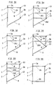
- FIGS. 24 to 29 belong to the same group and are common to one another in that each basically comprises a support post 1 and a V-shaped frame as a lateral member connected to the support post 1, the support post 1 and the V-shaped frame conjointly forming a right-angled triangle. Other structural points are the same as in the frame of FIG. 1.
- two sets of upper and lower V-shaped frames each comprising a horizontal member 2K and a diagonal member 2L are connected at their base ends to upper and lower flanges 7, 7 and an outer surface of a support post 1.
- the frame of FIG. 25, indicated at 3C, is the simplest frame, which forms a right-angled triangle as a whole. More specifically, the frame in question comprises a support post 1, flanges 7, 7 provided respectively at upper and intermediate positions of the support post 1, a V-shaped horizontal member 2c connected at base ends thereof to the upper flange 7 and a lower outer surface portion of the support post 1, and a metallic piece 13 as a connector provided at an outer end of the horizontal member 2c correspondingly to the upper flange 7.
- a horizontal reinforcing member H1 is mounted between the intermediate flange and a diagonal member 2c.
- a U-shaped reinforcing member HU is connected to all of the intermediate flange 7, an upper outer surface portion of the support post 1 and a diagonal member 2c.
- a reinforcing horizontal member H8 is connected to both the intermediate flange 7 and the diagonal member 2c, and a metallic piece 13 is provided at an outer end of the horizontal member H8.
- another horizontal member H9 is mounted between the support post 1 and the diagonal member 2c and in parallel with the horizontal member H8.
- a reinforcing frame H10 is connected between the outer end of the horizontal member 2c and the lower flange 7, the reinforcing frame H10 being in an inverted L shape in front view.
- the frames shown in FIGS. 31 to 38 which belong to the same group, are basically common to one another in that the whole of each frame is in a trapezoidal or rectangular shape in front view.
- FIG. 31 shows a frame 3A of a simple structure which is in a basic trapezoidal shape in front view. Its basic structure is the same as that of the frame shown in FIG. 1.
- the frame of FIG. 31 comprises a support post 1, flanges 7 provided at intermediate and upper positions of the support post 1, a frame 2A connected at base ends thereof to both the upper flange 7 and an lower outer surface portion of the support post 1, and metallic pieces 13, 13 provided at outer ends of the frame 2A correspondingly to the flanges 7, 7.
- the frame 2A is an integrally molded frame consisting of a horizontal member P, a vertical member Q and a diagonal member R.
- the support post 1 and the frame 2A form a trapezoidal shape in front view.
- one reinforcing horizontal member 2A1 is mounted between the support post 1 and the vertical member Q.
- a base end of the lower horizontal member 2A2 is connected to the intermediate flange 7.
- a reinforcing diagonal member 2A3 is mounted between an upper position of the support post 1 and an intermediate position of the frame 2A.
- base ends of horizontal members 2a, 2a are connected respectively to upper and lower flanges 7, 7, outer ends of the horizontal members 2a, 2a are connected together through a vertical support rod, and a metallic piece 13 is provided at a vertically central position of the support rod correspondingly to the intermediate flange 7.
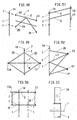
- FIGS. 39 to 41 which belong to another group, are common in that a horizontal member as a lateral member is connected to a flange provided at an intermediate position of a support post 1, the horizontal member extending in a direction different from the direction of an upper horizontal member.
- Other structural points are the same as in the frame of FIG. 1.
- the frame of FIG. 39 comprises a support post 1, flanges 7, 7 provided respectively at intermediate and upper positions of the support post 1, a horizontal member 2 as a lateral member connected at a base end thereof to the upper flange 7, a reinforcing member 2e mounted between an outer position of the horizontal member 2 and an upper outer surface portion of the support post 1, another horizontal member 4a as a lateral member connected to the intermediate flange 7 in a direction perpendicular to the horizontal member 2, and metallic pieces 13, 13 provided respectively at outer ends of the horizontal members 2 and 4a.
- the frame of FIG. 40 which has already been explained in connection with the prefabricated scaffolding of FIG. 69, comprises two support posts 1, 1, a balustrade 2' mounted between the support posts 1,1, a horizontal member 4b as a lateral member connected to an intermediate flange 7 on one support post 1, and a metallic piece 15 provided at an outer end of the horizontal member 4b.
- a pipe-like socket 14 is rotatably fitted on the support post 1 in close proximity to the intermediate flange 7, a horizontal member 4a is mounted to the socket 14, and a metallic piece 14a is provided at an outer end of the horizontal member 4a.
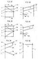
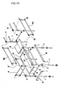
- Frame support posts shown in FIGS. 42 to 46 belong to the same group and are common to one another in that two support posts 1, 1 stand upright in parallel with each other. Though not shown, a lateral member is connected to an upper or lower flange 7 of one support post 1. As the case may be, these support posts are each used alone at an end portion of a prefabricated scaffolding without using any lateral member.
- the frame of FIG. 42 comprises two parallel support posts 1, 1 and a balustrade 2' mounted between upper flanges 7, 7 of the support posts 1, 1.
- a lateral member is connected detachably to one or both of upper and lower flanges 7,7.
- balustrade 2' is mounted between the support posts 1, 1.
- a diagonal member is mounted between the support posts 1, 1.
- a baseboard 8 is mounted between intermediate flanges 7, 7.
- a corrugated reinforcing member 35 is mounted between one balustrade 2' and the baseboard 8.
- an X-shaped reinforcing brace 26 is mounted between the support posts 1, 1.
- the frames shown in FIGS. 47 and 48 belong to the same group and are common to each other in that a lateral member is connected detachably to a support post.
- the frame of FIG. 47 comprises a support post 1 provided with two upper and lower flanges 7, 7 and a unitized lateral member X, the lateral member X comprising two horizontal members 2, 2 as balustrades, one baseboard 8 and one diagonal member 23.
- Base ends of the lateral member X are connected to the flanges 7, 7 on the support post 1 detachably through metallic pieces 13 and 8a which are provided respectively at an outer end of one horizontal member 2 and an outer end of the baseboard 8.
- a unitized lateral member Y is constituted by two horizontal members 2, 2 as balustrades and a V-shaped reinforcing member 24 connected to the horizontal members 2,2, and the lateral member Y is connected to flanges 7, 7 on the support post 1 detachably through metallic pieces 13 and 25 which are provided respectively at an outer end of one horizontal member 2 and an outer end of the reinforcing member 24.
- the frames shown in FIGS. 49 and 50 belong to the same group and are common to each other in that lateral members are provided respectively on both sides of a support post.
- the frame of FIG. 49 comprises a support post 1, flanges 7, 7 provided respectively at upper and intermediate positions of the support post 1, V-shaped frames 2D, 2D as lateral members disposed on both sides of the support post 1, a metallic piece 13 as a connector provided at an outer end of one V-shaped frame 2D correspondingly to the intermediate flange 7, and a metallic piece 13a as a third connector support member provided at an outer end of the other V-shaped frame 2D correspondingly to the metallic piece 13.
- two support posts 1, 1 are connected together through two intermediate horizontal members Q, a frame 2F as a lateral member comprising horizontal members and a vertical member is connected to one support post 1, and another frame 2F of the same shape as the one frame is connected to the other support post 1.
- metallic pieces 13 are provided at outer ends of one frame 2F, while metallic pieces 13a corresponding to the metallic pieces 13 and each constituted by a horizontal plate are provided at outer ends of the other frame 2F.
- FIG. 51 shows a still further example of a frame, which comprises two support posts 1, 1, two balustrades 2, 2 mounted between the two support posts 1, 1, two flanges mounted on one support post, and metallic pieces 13, 13 provided at side positions of the other support post 1 correspondingly to the flanges 7, 7.
- a V-shaped frame 2b as a lateral member is connected to a support post 1
- another V-shaped frame L4 is connected to the support post 1 in a direction perpendicular to the V-shaped frame 2b
- metallic pieces 13 are provided respectively at outer ends of the frames 2b and L4.
- FIG. 53 shows an upper portion of a support post 1. At an upper end of the support post 1 is formed a spigot portion 1a of a small diameter for insertion into another support post.
- FIGS. 54 to 58 show examples of flanges.
- a flange 7 shown in FIGS. 54(A) and (B) comprises a central disc 7a and an annular hook 7b formed along the outer periphery of the disc 7a. Through a central hole the flange 7 is fitted and fixed onto a support post 1.
- a flange 7 shown in FIGS. 55(A) and (B) comprises a disc 7a and eight retaining holes 7c formed in the circumferential direction of the disc 7a.
- a flange 7 shown in FIGS. 56(A) and (B) comprises a body 7d and ear portions formed in the body 7d in four directions spacedly at intervals of 90 degrees, and retaining holes 7g formed respectively in the ear portions 7e.
- a flange 7 shown in FIG. 57 comprises sockets 7f of a U-shaped section formed on the outer periphery of a support post 1 spacedly in four directions at intervals of 90 degrees. Base ends of the sockets 7f are welded at W to the support post 1.
- a flange 7 shown in FIG. 58 is rotatable while being held between two upper and lower support rings 123, 123 fixed onto the outer periphery of a support post 1, whereby a lateral member connected to the flange 7 is also made rotatable in any direction.
- FIG. 59 shows a further example of a lateral member and a connector.
- a clamp K is provided at an outer end of a horizontal member 2a.
- the clamp K as a connector comprises two clamp pieces K1 and K2 and a bolt BT for clamping the clamp pieces. Through the clamp K there is made connection to another support post or the like.
- FIGS. 63(A) and (B) show a scaffolding frame assembled using a frame embodying the present invention.
- the frame used is the frame 3C shown in FIG. 25 and plural such frames 3C are assembled in both vertical and lateral directions.
- upper and lower support posts 1, 1 are connected together, while frames 3C, 3C adjacent in the lateral direction are connected together by connecting the metallic piece 13 at an outer end of the frame member 2C in one support post 1 to the upper flange 7 of the other support post 1.
- the mounting angle of the metallic piece 13 in one frame member 2C relative to the flange 7 is changed.
- Scaffolding boards 125 are mounted along the scaffolding frame Z thus assembled.
- the frame members 2C not only are used as balustrades but also function as reinforcing braces in a diagonal direction.
- FIG. 64 shows a prefabricated scaffolding assembled by using the frame shown in FIG. 32. This is substantially the same as the prefabricated scaffolding shown in FIG. 60 which has already been referred to.
- such frames 3A as shown in FIG. 32 are assembled lengthwise and crosswise to form two rows of front and rear frames X, Y and scaffolding boards 5 are arranged laterally between the front and rear frames.
- a large number of frames 3A are laterally connected together, for example, by connecting the support post 1 of the right-hand frame to the metallic pieces 13, 13 of the left-hand frame.
- vertically arranged frames 3A are connected together by inserting the upper end of a lower support post 1 into the lower end of an upper support post 1. This connection is effected by using such a spigot portion 1a as shown in FIG. 53.
- each scaffolding board 5 are hooked to adjacent horizontal members to mount the scaffolding board.
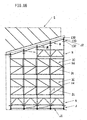
- each scaffolding board 5 in installing a prefabricated scaffolding around a building under construction, first an appropriate width of each scaffolding board 5 is determined, then such scaffolding boards 5 having the thus-determined width are installed through frames 3A', 3A' matching the width of each scaffolding board at corners of the building under construction, and thereafter other frames 3A, 3A are made laterally contiguous to the frames 3A', 3A' to constitute an L-shaped scaffolding.
- the strength of the prefabricated scaffolding as a whole is improved against lateral loads because it is assembled in L shape.
- each frame 3A' matching the width of each scaffolding board 5 at each corner is shorter in lateral size than each frame 3A, as shown in the figure.
- an adjustment of length may be made in conformity to the width of a side face of the building under construction.
- the frames X and Y can be formed easily by assembling a large number of frames 3A lengthwise and crosswise. Besides, when after the frames X and Y have been formed by assembling frames 3A at a lower stage, the same frames 3A are to be assembled one by one on the so-assembled lower frames, workers get on scaffolding boards 5 located at the lower stage and in this case balustrades are sure to be formed on the scaffolding boards 5 by means of horizontal members P and 2A1. That is, the assembling work can be done safely without using a life rope. Further, after completion of the prefabricated scaffolding, diagonal members R function as reinforcing braces.
- FIG. 65 shows a prefabricated scaffolding which has been constructed by assembling the frame of FIG. 40 lengthwise and crosswise. This is also substantially the same as the prefabricated scaffolding shown in FIG. 60. More specifically, frames X and Y are arranged at two rows in front and in the rear, and scaffolding boards 5 are mounted between the frames X and Y so as to be contiguous to one another in the lateral direction. Further, between end portions of the frames X and Y are mounted a balustrade 50 and a large-sized reinforcing member 51.
- the frames X and Y arranged at two rows in front and in the rear are connected together through horizontal members 4b, 4b secured to the support posts 1, and end portions of the scaffolding boards 5 are hooked to the horizontal members 4b, 4b.
- the front and rear frames X, Y can be formed easily by assembling a large number of frames 3 in both vertical and transverse directions. Moreover, even when frames 3 are assembled one by one at an upper stage, a worker can get on a lower scaffolding board 5 while balustrades 2' are sure to be formed, and thus the work can be carried out safely.
- FIG. 66 illustrates a structure assembled as scaffolding or shoring, which uses a frame 3C closely similar to the frame of FIG. 19 for example. More specifically, a large number of jacks J are disposed upright on the ground and are interconnected and reinforced by connecting members J1. Standard frames N are connected onto the jacks J and a plurality of frames 3C according to the present invention are connected horizontally and vertically onto the frames N. Further, a plurality of upper frames N are connected onto the frames 3C stepwise or horizontally and upper jacks J2 are mounted onto the upper frames N so as to be adjustable in height.
- the jacks J2 each comprise a bearer portion 130, a screw rod connected to the underside of the bearer portion 130, a flange 133 threadedly engaged with an intermediate part of the screw rod in a movable manner, and a nut and handle 132 threadedly engaged with a lower part of the screw rod.
- the screw rod is threadedly connected to a support post through the nut and handle 132.
- Support rods M capable of expansion and retraction are used for the frames N located at the upper end.
- the support rods M are each connected at both ends thereof to the flanges 133 of jacks J2.
- jacks J and J2 are used and flanges 133 are mounted on end portion aides of the screw rods 131, further, the connecting member J1 or the support rod M is connected between the flanges 133, so that it is possible to cope with a local load.
- the frames 3C each function as both balustrade and brace.
- FIGS. 67(A) and (B) illustrate a fixed type shoring of a square shape in plan formed by assembling, for example, such a frame as shown in FIG. 17 in a plural number in front-rear, right-left and up-down directions.
- frames adjacent to each other in the lateral direction are connected together through the metallic pieces of the left-hand frame and the flanges 7 on the support post 1 of the right-hand frame, and in this way a large number of frames are assembled successively in the lateral direction.
- Support posts 1, 1 adjacent to each other in the vertical direction are connected together by fitting the lower end of the upper support post onto the upper end of the lower support post 1.
- the upper end of the shoring in question bears the building S through jacks J, bearer portions 130 and sleepers 52 as is the case with the shoring of FIG. 66.
- FIGS. 68(A) and (B) illustrate a movable type shoring of a square shape in plan formed by assembling the same frames as above in front-rear, right-left and up-down directions.
- the shoring In the lower portion of the shoring are mounted frames 53 and casters 54 so that the shoring can be moved up to a desired position.
- Other structural points are the same as in the shoring of FIG. 67.
- FIGS. 69(A) and (B) illustrate a shoring formed by assembling the same frames as above.
- This shoring comprises four blocks Z1, Z2, Z3 and Z4.
- Each block comprises a large number of frames assembled vertically, and likewise frames are assembled on the front, rear and right, Left sides to form a square shape in cross section.
- the thus-assembled front, rear and right, left separate blocks Z1, Z2, Z3, Z4 are raised upright and connected together using horizontal members 55 to constitute a shoring in the shape of a square tower as a whole.
- How to connect adjacent frames laterally and vertically is the same as the connecting methods for the shorings illustrated in FIGS. 67 and 68.
- the building under construction is supported through jacks J, sleepers 52 and support members 56 in the same manner as above.
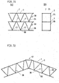
- FIGS. 70(A) and (B) illustrate a one-stage type support beam assembled by using the frame 3B shown in FIG. 20. A large number of such frames 3B are assembled together to constitute a triangular truss.
- FIGS. 71(A) and (B) illustrate a two-stage type support beam formed by connecting the same frames 3B as above in the lateral direction and also connecting them vertically in two stages. A large number of such frames 3B are used to constitute a square truss.
- FIG. 72 illustrates a support beam according to a still further embodiment of the present invention, which beam is formed in a chevron shape as a whole by using an auxiliary member 57 at a corner in contrast with the support beam of FIG. 70 which is horizontal as a whole. Other structural points are the same as in the support beam of FIG. 70.
- FIG.73 is a three-dimensional diagram of the support beam shown in FIG. 70.
- the support frames 3B are assembled in a three-dimensional form.
- support beam frames T each assembled by connecting frames 3B in the lateral direction are arranged at two rows in front and in the rear and are connected with each other through horizontal members 58 connected to flanges 7.
- scaffolding boards 5a or reinforcing boards are connected through their end-hooks onto the front and rear frames T with use of support posts 1.
- Other structural points are the same as in the support beam of FIG. 70.
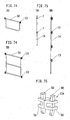
- FIGS. 74 to 82 illustrate reinforcing members for use in prefabricated scaffoldings, shorings and support beams according to the present invention.
- FIG. 74(A) illustrates a balustrade 50, as described previously in connection with the prefabricated scaffolding of FIG. 64.
- the balustrade 50 comprises a horizontal member, a U-shaped reinforcing member, and metallic pieces 13 provided at both ends of the horizontal member.
- FIG. 74(B) illustrates another balustrade 50, which comprises three horizontal members, two vertical members each for connecting end portions of the horizontal members with one another, and four metallic pieces 13 provided at both ends of the upper and lower horizontal members. How to use this balustrade 50 is the same as that for the balustrade 50 of FIG. 74(A).
- FIG. 75(A) illustrates a reinforcing or auxiliary support post 1A, with flanges 7, 7 being provided at intermediate and upper positions of the support post 1A.
- FIG. 75(B) also illustrates a reinforcing or auxiliary support post 1A, with a plurality of metallic pieces 13 being attached to a side face of the support poet 1A.
- the support post 1A is positioned along frames and connected to the frames through the metallic pieces 13.
- FIG. 76 illustrates a connector which is used in an auxiliary manner.
- the connector in question is used for connecting flanges 7, 7 of adjacent right and left supports 1, 1 with each other.
- This connector comprises shoes 59, 59 and wedges 60, 60 for insertion into holes formed in the shoes. Further, the shoes 59, 59 are fitted in perforated flanges 7, 7 and in this state the wedges 60, 60 are inserted into the holes of the shoes 59, 59 and of the flanges 7, 7.
- FIGS. 77 and 78 illustrate horizontal members or reinforcing members as lateral members.
- the horizontal member shown in FIG.77 is a fixed type which comprises a pipe 60 and metallic pieces 13, 13 is provided at both ends of the pipe 60.
- the metallic pieces 13, 13 are connected detachably to support post flanges 7, 7.
- the horizontal member shown in FIG. 78 is constituted by a pipe 60A capable of expansion and retraction, which pipe comprises an outer tube and an inner tube, with metallic pieces 13, 13 being provided at both ends of the pipe 60A.
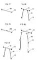
- FIGS. 79 to 82 illustrate ⁇ -shaped auxiliary members for the connection of support posts, which auxiliary members are each mounted between adjacent support posts, for example, in such a prefabricated scaffolding as shown in FIG. 65 or in a shoring.
- the auxiliary member shown in FIG. 79 comprises a horizontal pipe 61, metallic pieces 13, 13 provided at both ends of the pipe 61, two support legs 62, 62 suspended from end portions of the pipe, and metallic pieces 13, 13 provided on side faces of the lower ends of the support legs 62, 62.
- This auxiliary member is disposed between support posts 1, 1 of adjacent frames and the upper and lower metallic pieces 13 are connected to the support posts.
- auxiliary member shown in FIG. 80 which is substantially the same as the auxiliary member shown in FIG. 79, the upper ends of support legs 62, 62 are connected to the pipe 61 rotatably and detachably.
- auxiliary member shown in FIG. 81 which is a modification of the auxiliary member shown in FIG. 79, the support legs 62 are made longer, additional metallic pieces 13 are provided at intermediate positions of the support legs, and the upper ends of the support legs 62, 62 are connected to the underside of the pipe 61 detachably through pins and brackets.
- the auxiliary member shown in FIG. 82 which is substantially the same as the auxiliary members shown in FIGS .79 and 81, comprises a beam 63 as a strong horizontal member which serves also as a support beam, two support legs 62, 62 suspended from the underside of the beam 63, metallic pieces 13, 13 provided at both ends of the beam 63, and metallic pieces 13, 13 provided at intermediate and lower positions of each support leg 62.
- the auxiliary member in question is connected between the adjacent support posts through the metallic pieces 13. In this case, a large space is formed below the beam 63, which space permits workers and vehicles to pass therethrough.
- FIG. 83 illustrates a still further example of a horizontal member or reinforcing member as a lateral member, which comprises two or more horizontal or diagonal members 2H, 2H, a metallic piece 13 hinged to base ends of the horizontal or diagonal members 2H, and metallic pieces 13, 13 provided at the opposite ends of the horizontal or diagonal members.
- the lateral member in question can be connected to a support post 1 not only horizontally but also obliquely.
Priority Applications (1)
| Application Number | Priority Date | Filing Date | Title |
|---|---|---|---|
| EP98310780A EP1016766A1 (fr) | 1998-12-29 | 1998-12-29 | Cadres et structure composée par ces cadres |
Applications Claiming Priority (1)
| Application Number | Priority Date | Filing Date | Title |
|---|---|---|---|
| EP98310780A EP1016766A1 (fr) | 1998-12-29 | 1998-12-29 | Cadres et structure composée par ces cadres |
Publications (1)
| Publication Number | Publication Date |
|---|---|
| EP1016766A1 true EP1016766A1 (fr) | 2000-07-05 |
Family
ID=8235232
Family Applications (1)
| Application Number | Title | Priority Date | Filing Date |
|---|---|---|---|
| EP98310780A Withdrawn EP1016766A1 (fr) | 1998-12-29 | 1998-12-29 | Cadres et structure composée par ces cadres |
Country Status (1)
| Country | Link |
|---|---|
| EP (1) | EP1016766A1 (fr) |
Cited By (12)
| Publication number | Priority date | Publication date | Assignee | Title |
|---|---|---|---|---|
| WO2001025567A1 (fr) * | 1999-10-06 | 2001-04-12 | Niels Hollmann | Echafaudage pour le support de lourdes charges |
| EP1911907A1 (fr) * | 2006-10-11 | 2008-04-16 | Wilhelm Layher Verwaltungs-GmbH | Elément de cadre vertical en métal |
| WO2014019029A1 (fr) * | 2012-08-02 | 2014-02-06 | Form 700 Pty Ltd | Élément de support de coffrage |
| WO2014064341A1 (fr) * | 2012-10-23 | 2014-05-01 | Bertrand Lamy | Garde-corps monobloc pour tour d'étaiement, et tour d'étaiement le comportant |
| FR3005084A1 (fr) * | 2013-04-30 | 2014-10-31 | Godon Sas | Cadre pour tour d'etaiement avec garde-corps integre |
| US8978822B2 (en) | 2006-10-11 | 2015-03-17 | Wilhelm Layher Verwaltungs-Gmbh | Vertical frame of metal |
| CN105257035A (zh) * | 2015-09-09 | 2016-01-20 | 重庆杰渝建筑机械有限公司 | 模块式立体自主停车车库 |
| GB2537867A (en) * | 2015-04-29 | 2016-11-02 | Eandis | Shoring system and method of making an excavation with such shoring system |
| EP3155188A4 (fr) * | 2014-06-12 | 2017-11-01 | Hennejak Inc. | Section d'échafaudage |
| FR3057595A1 (fr) * | 2008-12-10 | 2018-04-20 | Mills | Perfectionnement aux tours d'etaiement. |
| US20180251989A1 (en) * | 2015-09-02 | 2018-09-06 | Atlantic Pacific Equipment, Inc. | Horizontal scaffold support component |
| GB2614062A (en) * | 2021-12-17 | 2023-06-28 | Beardsell & Sons Ltd | Trench support system |
Citations (8)
| Publication number | Priority date | Publication date | Assignee | Title |
|---|---|---|---|---|
| GB794431A (en) * | 1955-02-11 | 1958-05-07 | Mitchell Engineering Ltd | Improvements in or relating to scaffolding |
| GB1023921A (en) * | 1961-03-17 | 1966-03-30 | Hugh Stanford Evai I | Improvements in or relating to scaffold structures including prefabricated frame works |
| FR2069263A5 (fr) * | 1969-11-12 | 1971-09-03 | Mannesmann Leichtbau Gmbh | |
| FR2110136A5 (fr) * | 1970-10-30 | 1972-05-26 | Rapid Metal Developments Ltd | |
| FR2186042A5 (fr) * | 1972-05-24 | 1974-01-04 | Nicostrate Arma D | |
| US4541509A (en) * | 1982-01-15 | 1985-09-17 | Harsco Corporation | Shoring frame |
| DE3641349A1 (de) * | 1986-12-03 | 1988-06-16 | Ischebeck Friedrich Gmbh | Baustuetze |
| EP0383317A1 (fr) * | 1989-02-16 | 1990-08-22 | Langer geb. Layher, Ruth | Echafaudage avec poutre à treillis |
-
1998
- 1998-12-29 EP EP98310780A patent/EP1016766A1/fr not_active Withdrawn
Patent Citations (8)
| Publication number | Priority date | Publication date | Assignee | Title |
|---|---|---|---|---|
| GB794431A (en) * | 1955-02-11 | 1958-05-07 | Mitchell Engineering Ltd | Improvements in or relating to scaffolding |
| GB1023921A (en) * | 1961-03-17 | 1966-03-30 | Hugh Stanford Evai I | Improvements in or relating to scaffold structures including prefabricated frame works |
| FR2069263A5 (fr) * | 1969-11-12 | 1971-09-03 | Mannesmann Leichtbau Gmbh | |
| FR2110136A5 (fr) * | 1970-10-30 | 1972-05-26 | Rapid Metal Developments Ltd | |
| FR2186042A5 (fr) * | 1972-05-24 | 1974-01-04 | Nicostrate Arma D | |
| US4541509A (en) * | 1982-01-15 | 1985-09-17 | Harsco Corporation | Shoring frame |
| DE3641349A1 (de) * | 1986-12-03 | 1988-06-16 | Ischebeck Friedrich Gmbh | Baustuetze |
| EP0383317A1 (fr) * | 1989-02-16 | 1990-08-22 | Langer geb. Layher, Ruth | Echafaudage avec poutre à treillis |
Cited By (20)
| Publication number | Priority date | Publication date | Assignee | Title |
|---|---|---|---|---|
| WO2001025567A1 (fr) * | 1999-10-06 | 2001-04-12 | Niels Hollmann | Echafaudage pour le support de lourdes charges |
| EP1911907A1 (fr) * | 2006-10-11 | 2008-04-16 | Wilhelm Layher Verwaltungs-GmbH | Elément de cadre vertical en métal |
| US8978822B2 (en) | 2006-10-11 | 2015-03-17 | Wilhelm Layher Verwaltungs-Gmbh | Vertical frame of metal |
| FR3058432A1 (fr) * | 2008-12-10 | 2018-05-11 | Mills | Perfectionnement aux tours d'etaiement. |
| FR3057595A1 (fr) * | 2008-12-10 | 2018-04-20 | Mills | Perfectionnement aux tours d'etaiement. |
| AU2013299336B2 (en) * | 2012-08-02 | 2017-11-23 | Form 700 Pty Ltd | Formwork support element |
| WO2014019029A1 (fr) * | 2012-08-02 | 2014-02-06 | Form 700 Pty Ltd | Élément de support de coffrage |
| CN104662239A (zh) * | 2012-08-02 | 2015-05-27 | 福姆700私人有限公司 | 模板支撑元件 |
| JP2015523483A (ja) * | 2012-08-02 | 2015-08-13 | フォーム 700 ピーティーワイ リミテッドForm 700 Pty Ltd | 型枠支持要素 |
| RU2637693C2 (ru) * | 2012-08-02 | 2017-12-06 | Форм 700 Пти Лтд | Опорный элемент опалубки |
| US9546489B2 (en) | 2012-08-02 | 2017-01-17 | Form 700 Pty Ltd | Formwork support scaffold structure |
| WO2014064341A1 (fr) * | 2012-10-23 | 2014-05-01 | Bertrand Lamy | Garde-corps monobloc pour tour d'étaiement, et tour d'étaiement le comportant |
| WO2014177465A1 (fr) * | 2013-04-30 | 2014-11-06 | Godon Sas | Cadre pour tour d'etaiement avec garde-corps integre |
| FR3005084A1 (fr) * | 2013-04-30 | 2014-10-31 | Godon Sas | Cadre pour tour d'etaiement avec garde-corps integre |
| EP3155188A4 (fr) * | 2014-06-12 | 2017-11-01 | Hennejak Inc. | Section d'échafaudage |
| GB2537867A (en) * | 2015-04-29 | 2016-11-02 | Eandis | Shoring system and method of making an excavation with such shoring system |
| US20180251989A1 (en) * | 2015-09-02 | 2018-09-06 | Atlantic Pacific Equipment, Inc. | Horizontal scaffold support component |
| US10731362B2 (en) * | 2015-09-02 | 2020-08-04 | Atlantic Pacific Equipment, Inc. | Horizontal scaffold support component |
| CN105257035A (zh) * | 2015-09-09 | 2016-01-20 | 重庆杰渝建筑机械有限公司 | 模块式立体自主停车车库 |
| GB2614062A (en) * | 2021-12-17 | 2023-06-28 | Beardsell & Sons Ltd | Trench support system |
Similar Documents
| Publication | Publication Date | Title |
|---|---|---|
| US6450291B1 (en) | Frames and structures assembled by same | |
| KR100809886B1 (ko) | 교각 코핑 폼 시스템 및 이를 이용하여 교각을 시공하는방법 | |
| EP1016766A1 (fr) | Cadres et structure composée par ces cadres | |
| CN110733619A (zh) | 脚手架装置的角结构物 | |
| JP3700952B2 (ja) | 支保工 | |
| JP3878277B2 (ja) | 足場ユニット | |
| JP7446018B1 (ja) | コンクリート型枠装置の構成部材ユニット及びコンクリート型枠装置の構成部材ユニットの搬送方法 | |
| JPH08284439A (ja) | 重荷重形型枠支保工ならびにその部材 | |
| JPH06299691A (ja) | 枠組足場 | |
| JP3027130B2 (ja) | 吊り足場の組立構造 | |
| CA2267466A1 (fr) | Cadres et structures assemblees par ceux-ci | |
| AU775612B2 (en) | Frames and structures assembled by same | |
| JP4129460B2 (ja) | 枠組足場用荷受けステージの取付装置 | |
| KR100606985B1 (ko) | 프레임과 이 프레임에 의해 조립되는 구조체 | |
| NZ336067A (en) | Frames, typically for scaffolding with support post and lateral member, and connectable laterally and vertically to similar frames | |
| KR200213539Y1 (ko) | 안전 작업대의 프레임 | |
| JP3138112U (ja) | 屋根ユニット構造及びこれに使用する連結用金物 | |
| RU2183712C2 (ru) | Рамы и сборные рамные конструкции | |
| JP3700950B2 (ja) | 支保工 | |
| MXPA99007220A (en) | Frames and structures assembled using the same | |
| JP3033549U (ja) | 組立式足場 | |
| JPH07279418A (ja) | 仮設構造物 | |
| JP3084321B2 (ja) | 枠組足場用手摺枠 | |
| JP2521896Y2 (ja) | 足場装置 | |
| JP4047992B2 (ja) | 枠組足場の組立方法 |
Legal Events
| Date | Code | Title | Description |
|---|---|---|---|
| PUAI | Public reference made under article 153(3) epc to a published international application that has entered the european phase |
Free format text: ORIGINAL CODE: 0009012 |
|
| AK | Designated contracting states |
Kind code of ref document: A1 Designated state(s): AT BE CH CY DE DK ES FI FR GB GR IE IT LI LU NL PT SE |
|
| AX | Request for extension of the european patent |
Free format text: AL;LT;LV;MK;RO;SI |
|
| 17P | Request for examination filed |
Effective date: 20000918 |
|
| AKX | Designation fees paid |
Free format text: AT BE CH CY DE DK ES FI FR GB GR IE IT LI LU NL PT SE |
|
| STAA | Information on the status of an ep patent application or granted ep patent |
Free format text: STATUS: THE APPLICATION IS DEEMED TO BE WITHDRAWN |
|
| 18D | Application deemed to be withdrawn |
Effective date: 20060817 |