EP1015141B1 - In situ construction of containment vault under a radioactive or hazardous waste site - Google Patents
In situ construction of containment vault under a radioactive or hazardous waste site Download PDFInfo
- Publication number
- EP1015141B1 EP1015141B1 EP97952284A EP97952284A EP1015141B1 EP 1015141 B1 EP1015141 B1 EP 1015141B1 EP 97952284 A EP97952284 A EP 97952284A EP 97952284 A EP97952284 A EP 97952284A EP 1015141 B1 EP1015141 B1 EP 1015141B1
- Authority
- EP
- European Patent Office
- Prior art keywords
- grout
- trench
- fluid
- cut
- soil
- Prior art date
- Legal status (The legal status is an assumption and is not a legal conclusion. Google has not performed a legal analysis and makes no representation as to the accuracy of the status listed.)
- Expired - Lifetime
Links
- 230000002285 radioactive effect Effects 0.000 title abstract description 3
- 238000010276 construction Methods 0.000 title description 7
- 238000011065 in-situ storage Methods 0.000 title description 3
- 239000002901 radioactive waste Substances 0.000 title description 3
- 239000002920 hazardous waste Substances 0.000 title description 2
- 238000000034 method Methods 0.000 claims abstract description 64
- 239000011440 grout Substances 0.000 claims description 156
- 239000012530 fluid Substances 0.000 claims description 82
- 230000004888 barrier function Effects 0.000 claims description 58
- 238000005520 cutting process Methods 0.000 claims description 50
- 239000012188 paraffin wax Substances 0.000 claims description 44
- 239000000463 material Substances 0.000 claims description 36
- 229910000831 Steel Inorganic materials 0.000 claims description 28
- 239000010959 steel Substances 0.000 claims description 28
- XLYOFNOQVPJJNP-UHFFFAOYSA-N water Substances O XLYOFNOQVPJJNP-UHFFFAOYSA-N 0.000 claims description 22
- 239000007788 liquid Substances 0.000 claims description 20
- 239000002699 waste material Substances 0.000 claims description 18
- 238000005553 drilling Methods 0.000 claims description 13
- 239000000654 additive Substances 0.000 claims description 12
- 230000037361 pathway Effects 0.000 claims description 10
- 239000004094 surface-active agent Substances 0.000 claims description 10
- 230000000996 additive effect Effects 0.000 claims description 6
- 230000015572 biosynthetic process Effects 0.000 claims description 6
- 239000012466 permeate Substances 0.000 claims description 6
- 238000001816 cooling Methods 0.000 claims description 5
- 238000007789 sealing Methods 0.000 claims description 5
- 239000001993 wax Substances 0.000 claims description 4
- 230000009471 action Effects 0.000 claims description 3
- 230000003111 delayed effect Effects 0.000 claims description 3
- 230000005484 gravity Effects 0.000 claims description 2
- 230000000979 retarding effect Effects 0.000 claims description 2
- 229920001169 thermoplastic Polymers 0.000 claims description 2
- 239000004416 thermosoftening plastic Substances 0.000 claims description 2
- 238000004181 pedogenesis Methods 0.000 claims 4
- 230000001010 compromised effect Effects 0.000 claims 1
- 239000012768 molten material Substances 0.000 claims 1
- 230000000149 penetrating effect Effects 0.000 claims 1
- 239000002689 soil Substances 0.000 abstract description 94
- 238000009933 burial Methods 0.000 abstract description 13
- 239000011435 rock Substances 0.000 description 23
- 238000007667 floating Methods 0.000 description 17
- 229920001903 high density polyethylene Polymers 0.000 description 17
- 239000002002 slurry Substances 0.000 description 17
- 239000000126 substance Substances 0.000 description 16
- UQSXHKLRYXJYBZ-UHFFFAOYSA-N Iron oxide Chemical compound [Fe]=O UQSXHKLRYXJYBZ-UHFFFAOYSA-N 0.000 description 14
- 239000004700 high-density polyethylene Substances 0.000 description 13
- 230000002706 hydrostatic effect Effects 0.000 description 12
- 239000000203 mixture Substances 0.000 description 11
- 241000196324 Embryophyta Species 0.000 description 8
- 238000009412 basement excavation Methods 0.000 description 8
- 239000002173 cutting fluid Substances 0.000 description 8
- 230000004927 fusion Effects 0.000 description 8
- 239000004568 cement Substances 0.000 description 7
- -1 cementitious Substances 0.000 description 7
- 239000004927 clay Substances 0.000 description 7
- 239000004593 Epoxy Substances 0.000 description 6
- VYPSYNLAJGMNEJ-UHFFFAOYSA-N Silicium dioxide Chemical compound O=[Si]=O VYPSYNLAJGMNEJ-UHFFFAOYSA-N 0.000 description 6
- 230000006378 damage Effects 0.000 description 6
- 230000008569 process Effects 0.000 description 6
- 239000004698 Polyethylene Substances 0.000 description 5
- 238000007792 addition Methods 0.000 description 5
- 239000004567 concrete Substances 0.000 description 5
- 239000011019 hematite Substances 0.000 description 5
- 229910052595 hematite Inorganic materials 0.000 description 5
- LIKBJVNGSGBSGK-UHFFFAOYSA-N iron(3+);oxygen(2-) Chemical compound [O-2].[O-2].[O-2].[Fe+3].[Fe+3] LIKBJVNGSGBSGK-UHFFFAOYSA-N 0.000 description 5
- 229920001684 low density polyethylene Polymers 0.000 description 5
- 239000004702 low-density polyethylene Substances 0.000 description 5
- 239000003129 oil well Substances 0.000 description 5
- 229920000573 polyethylene Polymers 0.000 description 5
- 241000282472 Canis lupus familiaris Species 0.000 description 4
- 239000003082 abrasive agent Substances 0.000 description 4
- 239000010432 diamond Substances 0.000 description 4
- 229910003460 diamond Inorganic materials 0.000 description 4
- 238000001125 extrusion Methods 0.000 description 4
- 239000007789 gas Substances 0.000 description 4
- 230000006872 improvement Effects 0.000 description 4
- 238000002347 injection Methods 0.000 description 4
- 239000007924 injection Substances 0.000 description 4
- 238000012544 monitoring process Methods 0.000 description 4
- 230000035699 permeability Effects 0.000 description 4
- 239000000700 radioactive tracer Substances 0.000 description 4
- 239000004576 sand Substances 0.000 description 4
- 239000002680 soil gas Substances 0.000 description 4
- 239000000243 solution Substances 0.000 description 4
- 238000012360 testing method Methods 0.000 description 4
- 241000238631 Hexapoda Species 0.000 description 3
- KWYUFKZDYYNOTN-UHFFFAOYSA-M Potassium hydroxide Chemical compound [OH-].[K+] KWYUFKZDYYNOTN-UHFFFAOYSA-M 0.000 description 3
- 230000008901 benefit Effects 0.000 description 3
- 239000000440 bentonite Substances 0.000 description 3
- 229910000278 bentonite Inorganic materials 0.000 description 3
- SVPXDRXYRYOSEX-UHFFFAOYSA-N bentoquatam Chemical compound O.O=[Si]=O.O=[Al]O[Al]=O SVPXDRXYRYOSEX-UHFFFAOYSA-N 0.000 description 3
- 239000000356 contaminant Substances 0.000 description 3
- 238000006073 displacement reaction Methods 0.000 description 3
- 238000005755 formation reaction Methods 0.000 description 3
- 229920001519 homopolymer Polymers 0.000 description 3
- 238000002955 isolation Methods 0.000 description 3
- 239000004816 latex Substances 0.000 description 3
- 229920000126 latex Polymers 0.000 description 3
- 239000002925 low-level radioactive waste Substances 0.000 description 3
- 238000002844 melting Methods 0.000 description 3
- 230000008018 melting Effects 0.000 description 3
- 239000000047 product Substances 0.000 description 3
- WRIDQFICGBMAFQ-UHFFFAOYSA-N (E)-8-Octadecenoic acid Natural products CCCCCCCCCC=CCCCCCCC(O)=O WRIDQFICGBMAFQ-UHFFFAOYSA-N 0.000 description 2
- WXGNWUVNYMJENI-UHFFFAOYSA-N 1,1,2,2-tetrafluoroethane Chemical compound FC(F)C(F)F WXGNWUVNYMJENI-UHFFFAOYSA-N 0.000 description 2
- LQJBNNIYVWPHFW-UHFFFAOYSA-N 20:1omega9c fatty acid Natural products CCCCCCCCCCC=CCCCCCCCC(O)=O LQJBNNIYVWPHFW-UHFFFAOYSA-N 0.000 description 2
- QSBYPNXLFMSGKH-UHFFFAOYSA-N 9-Heptadecensaeure Natural products CCCCCCCC=CCCCCCCCC(O)=O QSBYPNXLFMSGKH-UHFFFAOYSA-N 0.000 description 2
- 239000005642 Oleic acid Substances 0.000 description 2
- ZQPPMHVWECSIRJ-UHFFFAOYSA-N Oleic acid Natural products CCCCCCCCC=CCCCCCCCC(O)=O ZQPPMHVWECSIRJ-UHFFFAOYSA-N 0.000 description 2
- ABLZXFCXXLZCGV-UHFFFAOYSA-N Phosphorous acid Chemical compound OP(O)=O ABLZXFCXXLZCGV-UHFFFAOYSA-N 0.000 description 2
- 241000283984 Rodentia Species 0.000 description 2
- 239000004115 Sodium Silicate Substances 0.000 description 2
- 230000003466 anti-cipated effect Effects 0.000 description 2
- 238000013459 approach Methods 0.000 description 2
- 230000008859 change Effects 0.000 description 2
- 238000011109 contamination Methods 0.000 description 2
- 238000005336 cracking Methods 0.000 description 2
- 230000000694 effects Effects 0.000 description 2
- 239000000839 emulsion Substances 0.000 description 2
- 238000005538 encapsulation Methods 0.000 description 2
- 239000003822 epoxy resin Substances 0.000 description 2
- 229910021485 fumed silica Inorganic materials 0.000 description 2
- 239000004746 geotextile Substances 0.000 description 2
- QXJSBBXBKPUZAA-UHFFFAOYSA-N isooleic acid Natural products CCCCCCCC=CCCCCCCCCC(O)=O QXJSBBXBKPUZAA-UHFFFAOYSA-N 0.000 description 2
- 238000005304 joining Methods 0.000 description 2
- 230000007774 longterm Effects 0.000 description 2
- 239000011159 matrix material Substances 0.000 description 2
- 238000005259 measurement Methods 0.000 description 2
- 230000007246 mechanism Effects 0.000 description 2
- ZQPPMHVWECSIRJ-KTKRTIGZSA-N oleic acid Chemical compound CCCCCCCC\C=C/CCCCCCCC(O)=O ZQPPMHVWECSIRJ-KTKRTIGZSA-N 0.000 description 2
- 239000002245 particle Substances 0.000 description 2
- 230000000737 periodic effect Effects 0.000 description 2
- 229920000647 polyepoxide Polymers 0.000 description 2
- 239000000843 powder Substances 0.000 description 2
- 239000012256 powdered iron Substances 0.000 description 2
- 238000005086 pumping Methods 0.000 description 2
- 230000002829 reductive effect Effects 0.000 description 2
- 230000003014 reinforcing effect Effects 0.000 description 2
- 230000008439 repair process Effects 0.000 description 2
- NTHWMYGWWRZVTN-UHFFFAOYSA-N sodium silicate Chemical compound [Na+].[Na+].[O-][Si]([O-])=O NTHWMYGWWRZVTN-UHFFFAOYSA-N 0.000 description 2
- 229910052911 sodium silicate Inorganic materials 0.000 description 2
- 239000007787 solid Substances 0.000 description 2
- 238000010408 sweeping Methods 0.000 description 2
- 238000009271 trench method Methods 0.000 description 2
- UONOETXJSWQNOL-UHFFFAOYSA-N tungsten carbide Chemical compound [W+]#[C-] UONOETXJSWQNOL-UHFFFAOYSA-N 0.000 description 2
- IEORSVTYLWZQJQ-UHFFFAOYSA-N 2-(2-nonylphenoxy)ethanol Chemical compound CCCCCCCCCC1=CC=CC=C1OCCO IEORSVTYLWZQJQ-UHFFFAOYSA-N 0.000 description 1
- 229910001369 Brass Inorganic materials 0.000 description 1
- 235000002566 Capsicum Nutrition 0.000 description 1
- RYGMFSIKBFXOCR-UHFFFAOYSA-N Copper Chemical compound [Cu] RYGMFSIKBFXOCR-UHFFFAOYSA-N 0.000 description 1
- DGAQECJNVWCQMB-PUAWFVPOSA-M Ilexoside XXIX Chemical compound C[C@@H]1CC[C@@]2(CC[C@@]3(C(=CC[C@H]4[C@]3(CC[C@@H]5[C@@]4(CC[C@@H](C5(C)C)OS(=O)(=O)[O-])C)C)[C@@H]2[C@]1(C)O)C)C(=O)O[C@H]6[C@@H]([C@H]([C@@H]([C@H](O6)CO)O)O)O.[Na+] DGAQECJNVWCQMB-PUAWFVPOSA-M 0.000 description 1
- 241001465754 Metazoa Species 0.000 description 1
- 239000006002 Pepper Substances 0.000 description 1
- 235000016761 Piper aduncum Nutrition 0.000 description 1
- 235000017804 Piper guineense Nutrition 0.000 description 1
- 244000203593 Piper nigrum Species 0.000 description 1
- 235000008184 Piper nigrum Nutrition 0.000 description 1
- 241000270295 Serpentes Species 0.000 description 1
- DWAQJAXMDSEUJJ-UHFFFAOYSA-M Sodium bisulfite Chemical compound [Na+].OS([O-])=O DWAQJAXMDSEUJJ-UHFFFAOYSA-M 0.000 description 1
- 229910052770 Uranium Inorganic materials 0.000 description 1
- YDONNITUKPKTIG-UHFFFAOYSA-N [Nitrilotris(methylene)]trisphosphonic acid Chemical compound OP(O)(=O)CN(CP(O)(O)=O)CP(O)(O)=O YDONNITUKPKTIG-UHFFFAOYSA-N 0.000 description 1
- 238000005299 abrasion Methods 0.000 description 1
- 150000001298 alcohols Chemical class 0.000 description 1
- 229940037003 alum Drugs 0.000 description 1
- 150000001412 amines Chemical class 0.000 description 1
- TZCXTZWJZNENPQ-UHFFFAOYSA-L barium sulfate Chemical compound [Ba+2].[O-]S([O-])(=O)=O TZCXTZWJZNENPQ-UHFFFAOYSA-L 0.000 description 1
- 239000010428 baryte Substances 0.000 description 1
- 229910052601 baryte Inorganic materials 0.000 description 1
- 238000009835 boiling Methods 0.000 description 1
- 229910021538 borax Inorganic materials 0.000 description 1
- 150000001642 boronic acid derivatives Chemical class 0.000 description 1
- 239000010951 brass Substances 0.000 description 1
- 238000005219 brazing Methods 0.000 description 1
- MTAZNLWOLGHBHU-UHFFFAOYSA-N butadiene-styrene rubber Chemical compound C=CC=C.C=CC1=CC=CC=C1 MTAZNLWOLGHBHU-UHFFFAOYSA-N 0.000 description 1
- 235000015155 buttermilk Nutrition 0.000 description 1
- 238000005266 casting Methods 0.000 description 1
- 239000000919 ceramic Substances 0.000 description 1
- 235000013351 cheese Nutrition 0.000 description 1
- 239000003638 chemical reducing agent Substances 0.000 description 1
- 239000002131 composite material Substances 0.000 description 1
- 150000001875 compounds Chemical class 0.000 description 1
- 239000002826 coolant Substances 0.000 description 1
- 230000018044 dehydration Effects 0.000 description 1
- 238000006297 dehydration reaction Methods 0.000 description 1
- 238000013461 design Methods 0.000 description 1
- 238000001514 detection method Methods 0.000 description 1
- 238000007599 discharging Methods 0.000 description 1
- 239000000428 dust Substances 0.000 description 1
- 229920001971 elastomer Polymers 0.000 description 1
- 239000000806 elastomer Substances 0.000 description 1
- 238000005516 engineering process Methods 0.000 description 1
- 230000007613 environmental effect Effects 0.000 description 1
- 229920006334 epoxy coating Polymers 0.000 description 1
- 230000003628 erosive effect Effects 0.000 description 1
- 150000002148 esters Chemical class 0.000 description 1
- 238000000605 extraction Methods 0.000 description 1
- 239000000835 fiber Substances 0.000 description 1
- 239000012065 filter cake Substances 0.000 description 1
- 239000012467 final product Substances 0.000 description 1
- 238000009472 formulation Methods 0.000 description 1
- 238000007710 freezing Methods 0.000 description 1
- 230000008014 freezing Effects 0.000 description 1
- 235000012208 gluconic acid Nutrition 0.000 description 1
- 239000003292 glue Substances 0.000 description 1
- 239000010438 granite Substances 0.000 description 1
- LNEPOXFFQSENCJ-UHFFFAOYSA-N haloperidol Chemical compound C1CC(O)(C=2C=CC(Cl)=CC=2)CCN1CCCC(=O)C1=CC=C(F)C=C1 LNEPOXFFQSENCJ-UHFFFAOYSA-N 0.000 description 1
- 238000005552 hardfacing Methods 0.000 description 1
- 239000000383 hazardous chemical Substances 0.000 description 1
- 239000012943 hotmelt Substances 0.000 description 1
- NLYAJNPCOHFWQQ-UHFFFAOYSA-N kaolin Chemical compound O.O.O=[Al]O[Si](=O)O[Si](=O)O[Al]=O NLYAJNPCOHFWQQ-UHFFFAOYSA-N 0.000 description 1
- 230000000670 limiting effect Effects 0.000 description 1
- 239000011344 liquid material Substances 0.000 description 1
- 230000000873 masking effect Effects 0.000 description 1
- 230000005012 migration Effects 0.000 description 1
- 238000013508 migration Methods 0.000 description 1
- 230000004048 modification Effects 0.000 description 1
- 238000012986 modification Methods 0.000 description 1
- 239000010705 motor oil Substances 0.000 description 1
- 239000010813 municipal solid waste Substances 0.000 description 1
- 150000002823 nitrates Chemical class 0.000 description 1
- 238000009659 non-destructive testing Methods 0.000 description 1
- 239000002736 nonionic surfactant Substances 0.000 description 1
- 229920000847 nonoxynol Polymers 0.000 description 1
- 239000003921 oil Substances 0.000 description 1
- 230000036961 partial effect Effects 0.000 description 1
- 229920003023 plastic Polymers 0.000 description 1
- 239000004033 plastic Substances 0.000 description 1
- 229920002401 polyacrylamide Polymers 0.000 description 1
- 229920005638 polyethylene monopolymer Polymers 0.000 description 1
- 229920000642 polymer Polymers 0.000 description 1
- 229920000417 polynaphthalene Polymers 0.000 description 1
- 229920001296 polysiloxane Polymers 0.000 description 1
- 239000012858 resilient material Substances 0.000 description 1
- 230000000452 restraining effect Effects 0.000 description 1
- 230000000630 rising effect Effects 0.000 description 1
- 150000003839 salts Chemical class 0.000 description 1
- 239000000523 sample Substances 0.000 description 1
- 229920006395 saturated elastomer Polymers 0.000 description 1
- 239000000565 sealant Substances 0.000 description 1
- 238000002791 soaking Methods 0.000 description 1
- 229910052708 sodium Inorganic materials 0.000 description 1
- 239000011734 sodium Substances 0.000 description 1
- 235000010267 sodium hydrogen sulphite Nutrition 0.000 description 1
- 239000004289 sodium hydrogen sulphite Substances 0.000 description 1
- 229920005552 sodium lignosulfonate Polymers 0.000 description 1
- 239000004328 sodium tetraborate Substances 0.000 description 1
- 235000010339 sodium tetraborate Nutrition 0.000 description 1
- 239000007921 spray Substances 0.000 description 1
- 238000003860 storage Methods 0.000 description 1
- BDHFUVZGWQCTTF-UHFFFAOYSA-M sulfonate Chemical compound [O-]S(=O)=O BDHFUVZGWQCTTF-UHFFFAOYSA-M 0.000 description 1
- 230000001360 synchronised effect Effects 0.000 description 1
- 239000012815 thermoplastic material Substances 0.000 description 1
- 239000010891 toxic waste Substances 0.000 description 1
- 230000005641 tunneling Effects 0.000 description 1
- JFALSRSLKYAFGM-UHFFFAOYSA-N uranium(0) Chemical compound [U] JFALSRSLKYAFGM-UHFFFAOYSA-N 0.000 description 1
- 238000013022 venting Methods 0.000 description 1
- 238000012795 verification Methods 0.000 description 1
- 230000000007 visual effect Effects 0.000 description 1
- 238000004017 vitrification Methods 0.000 description 1
- 239000011800 void material Substances 0.000 description 1
- 238000009736 wetting Methods 0.000 description 1
- 230000037303 wrinkles Effects 0.000 description 1
Images


Classifications
-
- E—FIXED CONSTRUCTIONS
- E02—HYDRAULIC ENGINEERING; FOUNDATIONS; SOIL SHIFTING
- E02D—FOUNDATIONS; EXCAVATIONS; EMBANKMENTS; UNDERGROUND OR UNDERWATER STRUCTURES
- E02D31/00—Protective arrangements for foundations or foundation structures; Ground foundation measures for protecting the soil or the subsoil water, e.g. preventing or counteracting oil pollution
-
- B—PERFORMING OPERATIONS; TRANSPORTING
- B09—DISPOSAL OF SOLID WASTE; RECLAMATION OF CONTAMINATED SOIL
- B09B—DISPOSAL OF SOLID WASTE NOT OTHERWISE PROVIDED FOR
- B09B1/00—Dumping solid waste
-
- G—PHYSICS
- G21—NUCLEAR PHYSICS; NUCLEAR ENGINEERING
- G21F—PROTECTION AGAINST X-RADIATION, GAMMA RADIATION, CORPUSCULAR RADIATION OR PARTICLE BOMBARDMENT; TREATING RADIOACTIVELY CONTAMINATED MATERIAL; DECONTAMINATION ARRANGEMENTS THEREFOR
- G21F9/00—Treating radioactively contaminated material; Decontamination arrangements therefor
- G21F9/28—Treating solids
- G21F9/34—Disposal of solid waste
-
- E—FIXED CONSTRUCTIONS
- E02—HYDRAULIC ENGINEERING; FOUNDATIONS; SOIL SHIFTING
- E02D—FOUNDATIONS; EXCAVATIONS; EMBANKMENTS; UNDERGROUND OR UNDERWATER STRUCTURES
- E02D2450/00—Gaskets
- E02D2450/10—Membranes
- E02D2450/105—Membranes impermeable
-
- E—FIXED CONSTRUCTIONS
- E02—HYDRAULIC ENGINEERING; FOUNDATIONS; SOIL SHIFTING
- E02D—FOUNDATIONS; EXCAVATIONS; EMBANKMENTS; UNDERGROUND OR UNDERWATER STRUCTURES
- E02D2600/00—Miscellaneous
- E02D2600/10—Miscellaneous comprising sensor means
-
- Y—GENERAL TAGGING OF NEW TECHNOLOGICAL DEVELOPMENTS; GENERAL TAGGING OF CROSS-SECTIONAL TECHNOLOGIES SPANNING OVER SEVERAL SECTIONS OF THE IPC; TECHNICAL SUBJECTS COVERED BY FORMER USPC CROSS-REFERENCE ART COLLECTIONS [XRACs] AND DIGESTS
- Y10—TECHNICAL SUBJECTS COVERED BY FORMER USPC
- Y10S—TECHNICAL SUBJECTS COVERED BY FORMER USPC CROSS-REFERENCE ART COLLECTIONS [XRACs] AND DIGESTS
- Y10S106/00—Compositions: coating or plastic
- Y10S106/90—Soil stabilization
Definitions
- the present invention relates generally to apparatus and methods for in situ construction of subsurface containment barriers for containing hazardous waste materials buried under the earth, and more particularly to a method of constructing a vault to encapsulate such hazardous materials so that contaminants are not released into the air or surrounding or underlying strata.
- the present invention further relates to a means for monitoring the continued integrity of the vault over many years and to a means for repairing any breaches which might occur over time.
- a gravity-anchored, air-tight cap structure is built on top of it.
- the HDPE liner under the block may be fusion bonded to the HDPE liner in the cap to achieve a very high degree of containment integrity.
- Passive soil gas pressure sensors under the cap and similar sensors in the ground outside the cap monitor the air pressure changes inside the structure as a function of normal atmospheric pressure changes due to weather. This data allows passive monitoring of the integrity of not only the horizontal barrier but also the entire containment structure. Moisture, sound, and chemical tracer levels may be passively monitored as leak and leak location indicators. Repair of damage is also possible by flooding the structure with liquid grout.
- a wire saw may also be used with molten paraffin grout to form a thin barrier roughly the thickness of the steel cable.
- This method maintains a circulating supply of molten paraffin in the pulling pipes which is ejected through holes in the pipe adjacent to the area being cut.
- the steel cable carries this molten paraffin into the cut and back to the surface.
- the paraffin is modified with additives that cause it to permeate into tight soils and form a barrier significantly thicker than the cut. Rapid cooling of the grout as the cut proceeds prevent excessive subsidence.
- An unlimited number of replacement jetting tubes or wire saw cables may be pulled into cutting position by the steel cables or the heated "pulling pipes" which are in the original directionally drilled holes. These may remelt a path through the previous cut.
- the preferred molten paraffin has a melting point between 49°C and 82°C (120° and 180°F), and is modified by the addition of a surfactant which allows the molten paraffin to soak into soils which are already water wet or damp, as well as dry soils which have a very low permeability to water.
- the paraffin may also be replaced by or blended with a low density polyethylene homopolymer.
- a mechanical earth cutting means consists of a flexible length of abrasive tensile member such as a steel cable or chain, the catenary section of which is cooled, cleaned and lubricated by a flow of grout from one or more ports in the adjacent pipes which are moved at intervals in synchronous with the net advance of the cutting means, and which itself is joined end to end and reciprocated or circulated in a continuous substantially horizontal loop between the two adjacent holes by a power driven apparatus that maintains tension on the cutting means against the face of the cut.
- Prior art has not utilized an abrasive cable saw in curving directionally drilled holes and has not anticipated coolant lines advancing through the holes with the cut.
- the initial cutting means and periodic replacement cutting means are pulled into the holes by means of the cables initially attached to the pulling pipes.
- Pipes which have one or more perforations are used to convey pressurized grout to the arc of the cable saw cut being formed. Movement of such discharge point being accomplished by moving the pipe through the ground or by moving a smaller inner pipe discharging between straddle packers positioned over one or more holes nearest the arc of the cut.
- a perimeter excavated trench filled with the dense grout covers each opening into the directionally drilled holes such that the grout may flow by gravity into those into the annulus between the pulling pipe and the hole and into any narrow cut between them formed by the cutting means. Grout may also flow out to relieve pressure. Flow from the grout filled trenches through the annulus to the cut area may be stimulated by a differential elevation of grout in the trench or the grout may flow from the pressurized grout pipe, which traverses the hole and discharges grout at any desired location along the length of the hole. Excess grout will flow up the annulus to the trench or will contribute to increasing the thickness of the barrier.
- an impermeable sheet such as high density polyethylene extrusion (HDPE) heat-fusion-seamed together as is known in the art, is attached by chains or other flexible linkage to two or more of the pulling pipes such that the impermeable sheet may be pulled through the layer of liquid grout under the floating block by pulling the pipes from the opposite end until the sheet extends out of the grout filled perimeter trench on all sides.
- the sheet is preferably heat-fusion-seamed so as to be wide and long enough to underlie the entire block and the outside berm of the perimeter trench. The outermost portions of the sheet are permitted to pucker into undulating folds to compensate for differences in length of the paths under the block.
- the orientation of such fluid jets being cyclically altered to increase the thickness and uniformity of the cut by reciprocating rotation of both ends of the tube an equal increment on each pulling stroke, or by other means substantially in unison such that all soil in the path of the tube can be impacted by one or more fixed jets.
- the surface of the catenary tube is abrasive and mechanically cuts the soil in its path as well as eroding it with fluid jets.
- An additional abrasive cable may be pulled into the cut by means of the color-coded, non-crossing cables on the pulling pipe. This cable can bypass the tube and perform an abrasive cutting job and then be withdrawn from either end.
- the entire cutting tube could also be circulated out of the ground and temporarily replaced by an abrasive cable or chain.
- the tube If the tube is damaged it can also be replaced in the same manner. This is a major improvement over jet cutting methods which have no recourse when they strike a hard object or if the jets plug. If the jetting tube has substantial enlargements along its length or at the slurry discharge points then it can not be circulated out of the hole if a problem should develop. This ability to recover from a structural failure, jet plugging, or a hard obstruction is critical to commercial use of the process.
- the grout material may be either a slow setting dense material capable of buoyantly supporting the overburden or may be a fast set or thermoplastic set material which sets before a large unsupported span exists.
- a low water, cementitious, latex polymer modified grout with iron oxide additives and a long term set retarder is preferred for buoyant barriers.
- a molten grouting material made from paraffin wax or polyethylene homopolymer and surfactant admixtures which enable it to mix with damp or wet soils and permeate farther into water impermeable soils is preferred for the non-buoyant process. Circulation of molten grout through the pulling pipes and the catenary tube can keep the material from setting during a work delay or even overnight.
- Paraffin supply lines from relatively hot and relatively cool but molten paraffin may be blended by a valve to rapidly adjust the temperature of the material with changing ground conditions. Blends of paraffin and polyethylene may also be used.
- a cap liner made of a similar polyethylene or paraffin mixture may be used in the top cap and heat fusion bonded to the bottom barrier to create a completely air tight seal of similar material. This cap material may be sprayed onto the surface of the cap as a liquid material and cured in place or it may be a pre-fabricated sheet.
- the above mentioned grouts have desirable properties for block encapsulation of buried low level radioactive waste.
- the molten wax and surfactant blends offer superior permeation into non-homogenous trash as well as good bonding and encapsulation of organic sludges. They offer a desirable matrix to stabilize the waste while it remains in the ground and also prevent airborne dust release during future retrieval. Since they are fully combustible they add no volume to the final waste matrix of a vitrification melter process.
- a shallow perimeter trench 7 is first excavated around the entire surface perimeter of the block to be isolated.
- a subsurface "block” or volume of the earth is defined by the ground level on its top and by a bottom comprised of a box-shaped or basin-shaped three dimensional mathematical "surface” which surrounds and underlies the block and rises upward to the ground level at the perimeter, forming a complete and continuous basin, fully enclosing the volume of earth.
- a directional drilling machine 1 then drills rows of pilot holes under the site, which define the basin's elongated shape.
- a pulling pipe with two or more non-crossed cables strapped to it is connected to the drill pipe and pulled through the pilot holes. After this operation each pilot hole contains a pulling pipe and two or more color coded steel cables.
- a diamond-wire saw machine 2 moves an abrasive cable 3 , formed by joined adjacent cables, through the pilot holes cutting a pathway between adjacent pilot holes.
- the abrasive cable 3 cuts the soil and assists the flow of the grout which carries soil particles to the surface. Pulling pipes 3, 5, and 8 remain in the pilot holes after the paths are cut.
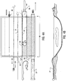
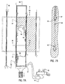
- FIG. 2 shows the pulling pipes 11 are in place defining a basin.
- Each pulling pipe 11 has one or more accompanying steel cables which are joined at the cutting end and threaded through a wire saw machine 13 at the other end.
- the wire saw machine 13 is pulled by a dozer 12 .
- a grout plant 15 supplies pressurized grout to the surface perimeter trench 16 and to one or more of the pulling pipes 11 through the flexible hose 14 .
- the grout exits the pulling pipes 11 through ports 18 .
- the grout cools and lubricates the cable saw 19 , and carries cuttings back to the surface perimeter trench 16 .
- the cut 17 is filled with the dense liquid grout, which supports the weight of the overburden soil.
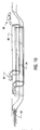
- FIG. 4 shows a directional drilling machine 28 placing a drill pipe in the ground defining the lower surface of the vault.
- Long “pulling pipes” are prepared with several steel cables running parallel along the length of the pipe and secured to the pipe by a temporary fastener such as steel bands on the ends and masking tape in the midpoint.
- the cables have color coded ends and do not cross one another.
- These pulling pipes are attached to the drill pipe in the holes and pulled into position 31 by a dozer 29, which pulls on the original drill pipe.
- One of the cables from each adjacent pipe 32 is joined together and threaded through a wire saw machine 35 .
- the cable may be used to draw a more specialized diamond-wire saw cable 33 into the cut.
- FIG. 5B shows that a block 38 floating on a layer of grout may not be of uniform density and due to its size may behave somewhat elastically.
- Steel cables or chains, 36 and 37 may be secured to anchor posts in the block and surrounding it to limit the total upward movement of the block as well as provide a centering effect 41 , as the block reaches full elevation.
- Grout from the plant 42 may fill the trench 40 at one end of the block but due to viscosity and friction effects may not initially fill the trench at the other end 39 , thus causing one end of the block to lift first. However, after a period of time the fluid levels will equalize and the block will level.
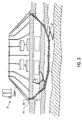
- a cap structure is sealed to the hardened grout wall 43 with a resilient material 44 (such as an elastomer or wax) to create an air-tight vault, as shown in FIG. 6.
- a resilient material 44 such as an elastomer or wax
- the impermeable polyethylene sheet 53 is fusion bonded to a similar polyethylene sheet 45 , in the cap structure.
- This top sheet is covered with layers of sand, concrete 46 , clay 47 , and topsoil, as is known in the art.
- the clay and sand are doped with bitter tasting additives to discourage plants, animals and insects from burrowing into it.
- Air pressure, humidity, temperature, sound and chemical sensors 48, 49, 50, and 51 are buried in the clean perimeter soil inside the vault and also outside the vault. These sensors allow passive measurement of the vault's integrity over time.
- a port may also be provided to introduce tracer gas into the containment structure.
- the paraffin grout displaces the soil and hardens a few meters behind the cut of the wire saw, before the length of the cut is wide enough to allow subsidence of the overburden.
- the paraffin grout is capable of soaking several inches into soils before it hardens and thus the final barrier may be several centimeters (inches) thick.
- Paraffin supply lines from relatively hot and relatively cool but molten paraffin may be blended by a simple valve to rapidly adjust the temperature of the material with changing ground conditions.
- the perimeter trench may be excavated by conventional means and filled with molten grout. If the paraffin grout is made sufficiently dense, by addition of iron oxide powder, to provide buoyant force on the block then a perimeter trench may be maintained with molten grout to produce a thick barrier as in FIG. 3.
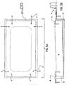
- the pulling pipes 66 and cable assembly have a length 65 , which is enough to allow one complete pass under the block with the end still exposed.
- a directional drilling machines 67 place a pipe down into the earth encircling the perimeter of a contaminated soil site below the tank, and then back to the surface, as shown in FIG. 8.
- a layer of high density fluid grout from a grout plant 70 is placed in a plane 72 below the tank 71 .
- a perimeter trench (68) is then excavated around the tanks to partial depth and is filled with high density fluid grout. The remaining depth is excavated with a clamshell or trackhoe excavator 69 releasing the block of ground containing the tank which floats upward as the grout flows into the plane under the tank.
- FIGs. 9A-F show a cross-sectional view of a long narrow burial site 73 being undercut and lifted by the method according to the present invention wherein a single pair of pilot holes 74 is employed.
- a wire saw 75 cuts between directionally drilled holes with a dense fluid to form a horizontal cut under a burial trench, as shown in FIG. 9A.
- a vertical perimeter trench 76 is excavated, as shown in FIG. 9B.
- the perimeter trench 76 is filled with dense grout 77, as shown in FIG. 9C.
- the soil block 78 then becomes buoyant and displaces upward to its final position 79 , with higher external soil berms in place, as shown in FIGs. 9D and 9E.
- the airtight cap structure 81 is bonded to the below ground barrier, as shown in FIG. 9F.
- a small test block is being undercut by the direct pull cable method.
- the dozer 89 pulls the cable 88 through the soil while the trench 87 is filled with the dense fluid grout supplied by the grout plant 90 .
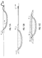
- one large sheet 99 is pulled under the free floating block by one or more dozers 98 , as shown in FIG. 13.
- the pulling pipes 100 are elastically attached 103 to the sheet at intervals. The edges of the sheet are allowed to pucker 102 to compensate for the differences in lengths.
- interlocking sheets of the impermeable liner material 105 are pulled under the free floating block by pulling pipes 108 , as shown in FIG. 14.
- the interlock 106 joins the sheets while allowing relative movement as the sheets are pulled through the liquid grout 104 .
- FIGs. 15A-B show another alternate embodiment of the basic method.
- This embodiment illustrates a catenary cutting method using a uniform tubular abrasive member 110 and a circulating pressurized fluid 55 directed at the cut as the tubular member is reciprocated around the arc of the cut by the motion of two hydraulic excavator trackhoes.
- the ends of the tubular member are rotated to allow a single fixed jet to sweep through at least 45° of arc so that it may strike substantially all of the soil in the path of the tubular member, as shown in FIG. 15B.
- the tubular member is a flexible high pressure tube of substantially uniform diameter extending from the surface down through the pilot holes and joined in a catenary arc.
- a directional drilling machine 1 such as those used by Eastman Cherrington Co, Houston, Texas, or direct push type machines such as those made by Charles Machine Works, which is known in the art, is used to drill a series of roughly parallel (in plan view) pilot holes 8 , under the site.
- the pilot holes may typically be spaced from 20 to 100 feet apart and do not have to be parallel or equidistant. They need only define the geometry of the barrier to be constructed.
- the holes typically enter the ground within the trench at an angle, descend to the desired depth, level off and run substantially horizontal, and then rise back to the trench at the opposite end of the block. Steering and verification of the position of such holes is well known in the art.
- any drilling fluid which returns to the surface may be used to verify that the holes are located in uncontaminated soil. If contamination is found, the hole may be plugged and a deeper pilot hole installed. Portions of the hole in unconsolidated soils may optionally be cased with a thin plastic sleeve 5.
- a smaller pipe with a straddle packer may be moved within the pulling pipe to direct liquid flow to any desired point along the pipe.
- the fluid may also be directed to any point by moving the pipe through the ground such that the holes are at the desired position.
- the pipe may also be used to draw additional wire saw cable into place if a cable breaks in service.
- the pipes may also be used to pull larger or more powerful wire saw cables or cutting devices or proving bars through the cut after the initial cut is made.
- a diamond-wire saw quarry saw such as the Pellegrini TDD 100 G, Verona, Italy, made for the extraction of granite blocks, is set up at one end of the directionally drilled pilot holes. These machines have been in use for many years.
- the diamond-wire saw is essentially a steel cable with abrasive materials bonded to it at intervals.
- the wire saw machine is a large power driven cable sheave which maintains tension on the cable and pulls a continuous loop of cable through the cut like a band saw.
- the diamond-wire saw steel cable from the first hole is joined in a loop back through the second hole to the wire saw machine and joined into a continuous cable.
- the method of joining steel cables may include a reweaving process which is known in the trade.
- the cable machine causes the cable to move in a continuous loop through the holes and places tension on the cable to cut a pathway between the first two pilot holes.
- Diamond abrasive sections of the cable do the cutting in rock, and also cut soil. In applications where rock is not anticipated, the cable abrasives may be optimized for fast soil cutting.
- a standard aircraft grade steel cable may also be used without abrasives to cut through soft soils.
- the words cable saw, cable, diamond-wire saw, diamond-wire saw quarry saw, and wire saw are used interchangeable to refer to a mechanical cutting means.
- the cutting fluid may optionally contain a clay dispersing additive such as sodium lignosulphonate or salt, to keep the clay from sticking to the cable.
- a high pressure fluid jet or mechanical brushes may be set up to continuously clean the cable as it comes out of the ground.
- the fluid exits the pulling pipe through small holes and flows back to the surface, applying a hydrostatic head to the area of the cut.
- the wire saw cable moves, it circulates this fluid from the entry side of the cut to the exit side and back to the surface trench.
- the wire saw cable also carries this fluid into the cut where it picks up cuttings and then returns to the surface trench with the returning cable.
- the used fluid may be picked up from the exit area of the trench and re-conditioned before placing it back into the trench.
- the fluid's density and the hydrostatic head from the surface trenches provide a balancing force which prevents the overburden soils from collapsing into the cut which the wire saw makes.
- the fluid is designed to flow into permeable soils and rock to a very limited degree, while forming a filter cake which the hydrostatic force may act against and support the overburden.
- the principle is similar to that of a deep horizontal oil well drilled through unconsolidated sands.
- additional grout may be added to the trench and injected through the pipes.
- the level of the grout fluid in the trench is gradually increased, which causes more grout fluid to flow into the cut and buoyantly lift the overburden soil as the thickness of the cut slowly and uniformly increases.
- the concept is like floating a ship out of dry dock. Addition of grout continues until the soil block has risen about 0,9 m (about 3 feet) See FIG. 2A. At this point the barrier thickness is also about 0,9 m (about 3 feet).
- the steel pipes which lie in the tracks of the pilot holes can now be utilized to pull a chain type proving bar or a High Density Polyethylene Extrusion (HDPE) liner under the floating block, see FIG. 5.
- HDPE High Density Polyethylene Extrusion
- a large sheet of HDPE could be fabricated by field fusion bonding techniques and pulled under the entire site in one motion.
- a reinforcing mesh of composite fiber could also be installed in this manner to increase the strength of cement based grout.
- Post tension cables or nondestructive testing devices could also be installed in the same manner.
- Earthen berms may be built up around the outer perimeter of the trench to allow higher grout levels to increase the lift of the block or to allow lift of a site with surface structures, or heavy objects.
- Anchored cables may be used to provide a force to keep the block floating in the geometric center of the liquid perimeter, see FIG. 6.
- the proprietary grout will remain fluid for several weeks and then harden into a rock with physical and chemical properties similar to ceramic tile. Properties of this fluid are tailored for the site and are sufficiently "filter cake-forming", that the fluid does not leak into the soil or rock excessively. Permeability of the preferred grout has been demonstrated to be approximately 10 -8 cm/sec. Compressive strength after 6 months is greater than 34,5.10 6 Pa (5000 psi). This grout has near zero shrinkage on set and is highly impermeable. It is suitable for both wet and desert dry conditions. As a liquid the grout has a marsh funnel viscosity less than 120 seconds and typically less than 70 seconds. The grout is inorganic and resistant to nitrate salt migration. A nonhardening version of the grout is also available for use as a cutting fluid in the wire saw operations. When mixed with the hardening version of the grout this dense cutting fluid will also harden.
- the special super dense grout is preferably composed of a type K other zero expansion cement to minimize the potential for stress cracking, mixed with water to an initial density of 1438 to 2396 kg/m 3 (12 to 20 pounds per gallon).
- a high density additive such as barite, brass or copper powder, uranium ore, or steel shot, but preferably iron oxide powder (hematite) such as is known in the art of oil well cementing and drilling fluids, is added to increase the final density to 2396 to 3595 kg/m 3 (20 to 30 pounds per gallon).
- a viscosity reducing admixture such as condensed polynaphthalene sulfonate, but preferably a salt-tolerant high range water reducer such as Halliburton CFR-3, available from Halliburton Services, in Houston, Texas is added at a concentration of 0.5 to 2 percent.
- a set retarding admixture based on lignosufonates, borates or gluconic acids, which are known in the art, but preferably an organic phosphonic acid such as Amino Tri Methylene Phosphonic Acid, which is made by Monsanto Chemical as a anti-scale additive.
- Other preferred additives include Fumed Silica, epoxy resins, and butadiene styrene latex emulsion.
- the above grout formulation properly proportioned, will form a nonsettling slurry which will remain liquid for several weeks and have a viscosity comparable to butter milk. After several weeks the slurry will harden. After curing for several months it will develop a high compressive strength.
- Such a slurry is as follows: 90 to 110 parts water (by weight), 150 parts type K cement, 300 to 400 parts powdered hematite (iron oxide), 20 to 40 parts fumed silica, 25 to 35 parts Latex emulsion, 30 to 60 parts CFR-3, and 0.2 to 0.8 parts organic phosphonic acid.
- This grout has a very low water content and produces a final product which can withstand very dry environments.
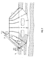
- Trace gasses may be introduced to aid in crack detection, location and repair. See FIG. 7. Introducing a small amount of Freon or other suitable tracer gasses into the containment structure should allow any subsurface cracks to be detected by soil gas probes placed around the perimeter. Injecting an odor producing chemical would allow regular monitoring by trained dogs. Dogs can be trained to dig at the source of the leak.
- a geo-textile is installed on top of the top HDPE liner with post tensioning and reinforcing installed above.
- a layer of sand with bitter tasting additives like pepper, alum, and borax is spread over the liner and a Low permeability concrete is cast on top of it to further discourage insects, plants, and rodents.
- a clay and soil cap is constructed above using these same additives to bury the concrete cap well below the frost line.
- Hollow pipes, placed into the wall and floor of the vault while in the liquid state may be used to perform radio frequency, electro-resistivity, or acoustic logging in the walls of the vault to locate cracks even if they do not cause a leak.
- Several acoustic transducers outside the vault sweeping from 20 to 60,000 cycles per second picked up by sensors buried in the interior of the structure could be used to locate cracks. Stress cracks will make sounds as they occur and can be passively detected.
- the preferred grout material would have a low electrical conductivity to allow resistive logging between the inside and the outside of the containment structure.
- Directionally drilled holes would be placed along the bottom outboard edges of a trench at the desired depth. This could be well into the basalt rock layer. These pilot holes would curve back to the surface on each end of the burial trench. Diamond wire quarry saw cables, attached to both ends of a pipe, preferably 6,1 cm (2-3/8 inch) oil well steel tubing, would be pulled into each hole as the drill pipe is removed.
- the cables from one hole to another would be joined at the surface into a continuous length and threaded through the wire saw machine.
- Two separate, bermed, elevated pits "A” and “B” would be constructed around each of the pilot hole openings on the wire saw machine end of the burial trench.
- a single trench “C” would be constructed connecting both of the pilot holes on the opposite end of the burial trench.
- An alternate method of construction may be used in soil or rock which may be cut more rapidly. This method is expected to be useful in hard soil in which a trench will stand open without support and has little chance of large fractures or voids.
- the vertical perimeter trench is first excavated to full depth.
- the wire sawing equipment is then positioned in the trench to cut loose the base of the block on a horizontal plane. This may be accomplished by placing cable pulleys in the trench or by entering the base of one end of the trench with directional drilled holes, through which the cable saw is threaded.
- the trench will be filled with a super dense grout which is denser than the soil block and which is designed to remain fluid during the duration of the work.
- This method the set properties of the super dense grout must be delayed until the cut is complete.
- This method may not require directional drilling at sites where deep conventional excavation of the perimeter trench is possible.
- This method forms a rectangular block instead of a gently curved basin structure. Additional sloping excavations on each end could be added to facilitate introduction of a plastic liner material.
- a special variation of this method is possible in very soft soil or in a small test site.
- a trench is excavated dry in a U shape with the ends of the U tapering back to the surface and a cross ditch in the full depth portion such that the waste area is surrounded.
- a steel cable is laid in the bottom of the trench with ends extending from the bottom of the U and connecting to a pulling means such as a large dozer.
- the tapering portion of the trench is backfilled to hold the cables in place.
- the remaining trench is filled with a grout that is more dense than the soil but still fluid.
- the dozer pulls the cable through the soft soil like a cheese slicer, making a cut which is instantly filled with grout. This action forms a continuous layer of grout under the soil block which thickens as the grout displaces the block upward.
- Anchor cables keep the soil block centered in the excavation. When the grout hardens it will form a seamless basement structure.
- Another alternate method involves forming a directionally drilled hole which enters the ground outside the waste area perimeter, descends to depth and levels off, proceeds around the perimeter of the area to be isolated, (completely encircling it), and then returns to the surface near the point of entry.
- the wire saw cable is drawn through this circular path as the drill is withdrawn. As the wire saw tightens it cuts under the area to be isolated.
- a large circular cut is formed under the site. See FIG. 8.
- the cut is filled with dense fluid as it is cut, as is done in the preferred method. This dense fluid fills the cut and the directionally drilled holes back to the surface to provide hydrostatic support for the block of soil.
- This dense fluid may be a nonhardening material which could remain in place for many months before the next phase of the project.
- the fluid would be designed to be slightly heavier or lighter than the grout and would have the ability to seal off small leak pathways or permeable formations.
- Molten paraffin circulated through a catenary arcuate tube at high pressure and rate while the tube itself is reciprocated through directionally drilled holes to the advancing cut.
- Typical pressures would be from 1.38.10 7 to 6.9.10 7 Pa (2000 psi to 10,000 psi) controlled by a spring loaded pinch valve on the recirculation line which automatically limits the pressure in the line. Circulation rates are sufficient to prevent particles from settling out and to keep temperature uniform. Holes or hardened ports in the forward facing surface of the tube eject the heated liquid into the soil at high kinetic energy causing the soil to be eroded and substantially replaced by the molten paraffin. This allows the tube to advance forward laterally.
- the inventor has noted that the width of the cut formed by a single jet varies significantly with soil type and jetting factors. If the jets do not make a cut at least as thick as the diameter of the tube then the device can not advance except by mechanical abrasion.
- the ends of the pipe may be automatically rotated by a mechanical "J-Slot'' mechanism such as is common in the art of oil well down-hole tools. The mechanism rotates one increment each time the tube is placed in tension and released.
- the paraffin both permeates into the soil and cools to a solid state. Paraffin which fractures away from the barrier will undergo rapid cooling and will harden and seal off. The injection temperature, and the cooling rate are such that the paraffin hardens before a large enough liquid area of the cut exists to allow subsidence of the overburden to pinch out the barrier. Since fresh molten paraffin is always circulating through the tube, the immediate area of the cut will always remain molten even if reciprocation stops. If the pipe breaks or becomes stuck a new tube may be pulled into position by melting a path through the previous cut. An unlimited number of replacement jetting tubes or wire saw cables may be pulled into cutting position by the heated "pulling pipes" which are in the original directionally drilled holes. An abrasive wire saw cable or chain, may also precede the jetting tube by a few feet to cut through hard objects and reduce the stress on the tube.
- Molten low density polyethylene Homopolymer such as Marcus 4040 which melt at 83°C (181.4° F). may be utilized in a similar manner to the paraffin to increase chemical resistance properties. It may also be modified to enhance its performance in wet soils by the additions of surfactant blends.
- An example of a nonionic blend is 7 parts by weight ethoxylated alcohol, .56 parts potassium hydroxide, and 21 parts sodium bisulphite.
- An ionic blend could be made with equal parts by weight of oleic acid and an amine.
- polyethylene is used as the primary grout, the HDPE top liner may be fusion bonded directly to the bottom barrier. This material may also be used as a hot melt glue to bond the paraffin to an HDPE top liner.
- the low density polyethylene homopolymers may be blended with the paraffin wax at a concentration of from 2 to 10 percent weight percent to improve its wetting properties, impermeability, and chemical resistance.
- Molten paraffin may be especially useful for constructing barrier vaults in rock which has large cracks or fissures such as the basalt rock layers which exist in Idaho. As the molten wax enters a fissure and begins to escape from the area where the barrier is to be formed it loses heat and solidifies quickly. This tends to seal off the fissure. This approach should work in both water saturated and vadose zones.
Landscapes
- Engineering & Computer Science (AREA)
- Environmental & Geological Engineering (AREA)
- Life Sciences & Earth Sciences (AREA)
- General Engineering & Computer Science (AREA)
- General Life Sciences & Earth Sciences (AREA)
- High Energy & Nuclear Physics (AREA)
- Paleontology (AREA)
- Civil Engineering (AREA)
- Hydrology & Water Resources (AREA)
- Structural Engineering (AREA)
- Physics & Mathematics (AREA)
- Mining & Mineral Resources (AREA)
- Bulkheads Adapted To Foundation Construction (AREA)
- Consolidation Of Soil By Introduction Of Solidifying Substances Into Soil (AREA)
- Processing Of Solid Wastes (AREA)
- Underground Structures, Protecting, Testing And Restoring Foundations (AREA)
- Filling Or Discharging Of Gas Storage Vessels (AREA)
- Curing Cements, Concrete, And Artificial Stone (AREA)
Applications Claiming Priority (3)
| Application Number | Priority Date | Filing Date | Title |
|---|---|---|---|
| US761273 | 1996-12-06 | ||
| US08/761,273 US5890840A (en) | 1995-12-08 | 1996-12-06 | In situ construction of containment vault under a radioactive or hazardous waste site |
| PCT/US1997/022220 WO1998024566A1 (en) | 1996-12-06 | 1997-12-05 | In situ construction of containment vault under a radioactive or hazardous waste site |
Publications (3)
| Publication Number | Publication Date |
|---|---|
| EP1015141A4 EP1015141A4 (en) | 2000-07-05 |
| EP1015141A1 EP1015141A1 (en) | 2000-07-05 |
| EP1015141B1 true EP1015141B1 (en) | 2006-06-21 |
Family
ID=25061732
Family Applications (1)
| Application Number | Title | Priority Date | Filing Date |
|---|---|---|---|
| EP97952284A Expired - Lifetime EP1015141B1 (en) | 1996-12-06 | 1997-12-05 | In situ construction of containment vault under a radioactive or hazardous waste site |
Country Status (7)
Families Citing this family (87)
| Publication number | Priority date | Publication date | Assignee | Title |
|---|---|---|---|---|
| US5890840A (en) | 1995-12-08 | 1999-04-06 | Carter, Jr.; Ernest E. | In situ construction of containment vault under a radioactive or hazardous waste site |
| JP2930922B2 (ja) * | 1997-07-29 | 1999-08-09 | 太陽工業株式会社 | 廃棄物処分場 |
| US5961437A (en) * | 1997-09-08 | 1999-10-05 | Lockheed Martin Idaho Technologies Company | Multi-layer waste containment barrier |
| US6342650B1 (en) * | 1999-06-23 | 2002-01-29 | VALFELLS áGUST | Disposal of radiation waste in glacial ice |
| US6648552B1 (en) | 1999-10-14 | 2003-11-18 | Bechtel Bwxt Idaho, Llc | Sensor system for buried waste containment sites |
| WO2001040583A1 (en) * | 1999-12-06 | 2001-06-07 | Bechtel Bwxt Idaho, Llc | Advanced containment system |
| US6401400B1 (en) | 2000-03-15 | 2002-06-11 | Newbasis, Llc | Industrial vault |
| AU2001260247A1 (en) | 2000-04-24 | 2001-11-07 | Shell Canada Limited | A method for treating a hydrocarbon-containing formation |
| US7153061B2 (en) * | 2000-12-04 | 2006-12-26 | Battelle Energy Alliance, Llc | Method of in situ retrieval of contaminants or other substances using a barrier system and leaching solutions |
| US7056063B2 (en) * | 2000-12-04 | 2006-06-06 | Battelle Energy Alliance, Llc | Apparatus for indication of at least one subsurface barrier characteristic |
| US6910829B2 (en) * | 2000-12-04 | 2005-06-28 | Battelle Energy Alliance, Llc | In situ retreival of contaminants or other substances using a barrier system and leaching solutions and components, processes and methods relating thereto |
| US7160061B2 (en) * | 2000-12-04 | 2007-01-09 | Battelle Energy Alliance, Llc | Subterranean barriers including at least one weld |
| US6758634B2 (en) * | 2001-02-06 | 2004-07-06 | Bechtel Bwxt Idaho, Llc | Subsurface materials management and containment system |
| US6918442B2 (en) | 2001-04-24 | 2005-07-19 | Shell Oil Company | In situ thermal processing of an oil shale formation in a reducing environment |
| US6973758B2 (en) | 2001-05-14 | 2005-12-13 | Rad Technology, Llc | Shielded structure for radiation treatment equipment and method of assembly |
| US6991045B2 (en) | 2001-10-24 | 2006-01-31 | Shell Oil Company | Forming openings in a hydrocarbon containing formation using magnetic tracking |
| WO2004022255A2 (en) * | 2002-09-03 | 2004-03-18 | Terraquest Technologies, Ltd. | Application of inert gas mixtures to prevent and/or to control sulfide mineral oxidation and the generation of acid rock drainage |
| US6892814B2 (en) * | 2002-12-19 | 2005-05-17 | Halliburton Energy Services, Inc. | Cement compositions containing coarse barite, process for making same and methods of cementing in a subterranean formation |
| US6874976B2 (en) * | 2003-02-21 | 2005-04-05 | Kyokado Engineering Co., Ltd. | Multipoint grouting method and apparatus therefor |
| US7114880B2 (en) * | 2003-09-26 | 2006-10-03 | Carter Jr Ernest E | Process for the excavation of buried waste |
| US7037040B2 (en) * | 2004-02-02 | 2006-05-02 | Applied Geotechnical Engineering And Construction, Inc. (Agec, Inc.) | Method for the placement of subterranean electrodes |
| CA2503256A1 (en) * | 2004-04-06 | 2005-10-06 | Claude J. Degarie | Membrane cover having a protective layer to prevent deterioration of uv stabilizers therein |
| US7070359B2 (en) * | 2004-05-20 | 2006-07-04 | Battelle Energy Alliance, Llc | Microtunneling systems and methods of use |
| US7456418B1 (en) * | 2004-11-15 | 2008-11-25 | Visible Assets, Inc | RF-enablement of auditable storage for hazardous materials |
| US7938904B1 (en) * | 2005-02-28 | 2011-05-10 | B. Ryland Wiggs | Cementitious grout and methods of using same |
| US8070840B2 (en) | 2005-04-22 | 2011-12-06 | Shell Oil Company | Treatment of gas from an in situ conversion process |
| US8287050B2 (en) * | 2005-07-18 | 2012-10-16 | Osum Oil Sands Corp. | Method of increasing reservoir permeability |
| US7381010B2 (en) * | 2005-08-29 | 2008-06-03 | Worth Wind, Inc. (Assignee Of The Interest Of Grams, Crass, And Riess) | System and method for removal of buried objects |
| KR101359313B1 (ko) * | 2005-10-24 | 2014-02-10 | 쉘 인터내셔날 리써취 마트샤피지 비.브이. | 현장 열처리로부터 생성된 액체로부터 알킬화 탄화수소를생성하는 방법 |
| US7647967B2 (en) * | 2006-01-12 | 2010-01-19 | Jimni Development LLC | Drilling and opening reservoir using an oriented fissure to enhance hydrocarbon flow and method of making |
| US8261820B2 (en) * | 2006-01-12 | 2012-09-11 | Jimni Development LLC | Drilling and opening reservoirs using an oriented fissure |
| WO2007124378A2 (en) * | 2006-04-21 | 2007-11-01 | Osum Oil Sands Corp. | Method of drilling from a shaft for underground recovery of hydrocarbons |
| KR20090007453A (ko) | 2006-04-21 | 2009-01-16 | 쉘 인터내셔날 리써취 마트샤피지 비.브이. | 온도 제한 히터에서의 선택된 특성을 위한 조절용 합금 조성물 |
| ES2296522B1 (es) * | 2006-05-26 | 2009-04-01 | Europea De Minerales Y Derivados, S.L. | Masa pesada para la fabricacion de productos con alta capacidad de radio-proteccion. |
| WO2008024147A1 (en) | 2006-08-23 | 2008-02-28 | Exxonmobil Upstream Research Company | Composition and method for using waxy oil-external emulsions to modify reservoir permeability profiles |
| WO2008033536A2 (en) * | 2006-09-14 | 2008-03-20 | Carter Ernest E | Method of forming subterranean barriers with molten wax |
| US7677673B2 (en) * | 2006-09-26 | 2010-03-16 | Hw Advanced Technologies, Inc. | Stimulation and recovery of heavy hydrocarbon fluids |
| US20080078552A1 (en) * | 2006-09-29 | 2008-04-03 | Osum Oil Sands Corp. | Method of heating hydrocarbons |
| US7644769B2 (en) * | 2006-10-16 | 2010-01-12 | Osum Oil Sands Corp. | Method of collecting hydrocarbons using a barrier tunnel |
| US7677310B2 (en) | 2006-10-20 | 2010-03-16 | Shell Oil Company | Creating and maintaining a gas cap in tar sands formations |
| WO2008064305A2 (en) | 2006-11-22 | 2008-05-29 | Osum Oil Sands Corp. | Recovery of bitumen by hydraulic excavation |
| CN101680286A (zh) | 2007-04-20 | 2010-03-24 | 国际壳牌研究有限公司 | 电隔离绝缘导体加热器 |
| KR100830437B1 (ko) | 2007-04-24 | 2008-05-20 | 주식회사 한국콘젝트시스템 | 그라우트 조성물 |
| US9133596B2 (en) * | 2007-05-31 | 2015-09-15 | Ernest E. Carter, Jr. | Method for construction of subterranean barriers cross reference to related patent applications |
| US7656050B2 (en) * | 2007-09-27 | 2010-02-02 | William Riley | Hydroelectric pumped-storage |
| US20090084707A1 (en) * | 2007-09-28 | 2009-04-02 | Osum Oil Sands Corp. | Method of upgrading bitumen and heavy oil |
| JP5551600B2 (ja) | 2007-10-19 | 2014-07-16 | シエル・インターナシヨネイル・リサーチ・マーチヤツピイ・ベー・ウイ | 地表下地層の加熱用誘導ヒーター |
| WO2009077866A2 (en) * | 2007-10-22 | 2009-06-25 | Osum Oil Sands Corp. | Method of removing carbon dioxide emissions from in-situ recovery of bitumen and heavy oil |
| US20090139716A1 (en) * | 2007-12-03 | 2009-06-04 | Osum Oil Sands Corp. | Method of recovering bitumen from a tunnel or shaft with heating elements and recovery wells |
| US7837906B1 (en) | 2007-12-21 | 2010-11-23 | Versaflex, Inc. | Systems and methods for treating air chambers in aeration basins of wastewater treatment facilities |
| US8176982B2 (en) * | 2008-02-06 | 2012-05-15 | Osum Oil Sands Corp. | Method of controlling a recovery and upgrading operation in a reservoir |
| CA2718767C (en) | 2008-04-18 | 2016-09-06 | Shell Internationale Research Maatschappij B.V. | Using mines and tunnels for treating subsurface hydrocarbon containing formations |
| CA2718885C (en) | 2008-05-20 | 2014-05-06 | Osum Oil Sands Corp. | Method of managing carbon reduction for hydrocarbon producers |
| EP2128109A1 (en) * | 2008-05-28 | 2009-12-02 | Schlumberger Holdings Limited | Solids Free Sealing Fluid |
| EP2313708A4 (en) | 2008-06-13 | 2014-04-09 | Michael J Parrella | SYSTEM AND METHOD FOR CAPTURING GEOTHERMAL HEAT FROM THE INTERIOR OF A FORWELL WELL TO GENERATE ELECTRICITY |
| US7740070B2 (en) * | 2008-06-16 | 2010-06-22 | Halliburton Energy Services, Inc. | Wellbore servicing compositions comprising a density segregation inhibiting composite and methods of making and using same |
| US9423158B2 (en) | 2008-08-05 | 2016-08-23 | Michael J. Parrella | System and method of maximizing heat transfer at the bottom of a well using heat conductive components and a predictive model |
| US20100270001A1 (en) * | 2008-08-05 | 2010-10-28 | Parrella Michael J | System and method of maximizing grout heat conductibility and increasing caustic resistance |
| WO2010045101A1 (en) | 2008-10-13 | 2010-04-22 | Shell Oil Company | Using self-regulating nuclear reactors in treating a subsurface formation |
| WO2010074980A1 (en) * | 2008-12-10 | 2010-07-01 | Carter Ernest E Jr | Method and apparatus for increasing well productivity |
| US8434555B2 (en) | 2009-04-10 | 2013-05-07 | Shell Oil Company | Irregular pattern treatment of a subsurface formation |
| RU2417466C1 (ru) * | 2009-12-15 | 2011-04-27 | Государственное образовательное учреждение высшего профессионального образования "Санкт-Петербургский государственный горный институт имени Г.В. Плеханова (технический университет)" | Хранилище отходов |
| US9033042B2 (en) | 2010-04-09 | 2015-05-19 | Shell Oil Company | Forming bitumen barriers in subsurface hydrocarbon formations |
| US8631866B2 (en) | 2010-04-09 | 2014-01-21 | Shell Oil Company | Leak detection in circulated fluid systems for heating subsurface formations |
| US8701768B2 (en) | 2010-04-09 | 2014-04-22 | Shell Oil Company | Methods for treating hydrocarbon formations |
| US8875788B2 (en) | 2010-04-09 | 2014-11-04 | Shell Oil Company | Low temperature inductive heating of subsurface formations |
| HU1000378D0 (en) | 2010-07-19 | 2010-11-29 | G I C Ipari Szolgaltato Es Kereskedelmi Kft | Method and apparatus for transforming salts and acids containing boron and/or solutions thereof into solid borosilicate at low temperature |
| US8646846B2 (en) | 2010-08-23 | 2014-02-11 | Steven W. Wentworth | Method and apparatus for creating a planar cavern |
| WO2012027110A1 (en) | 2010-08-23 | 2012-03-01 | Wentworth Patent Holdings Inc. | Method and apparatus for creating a planar cavern |
| WO2013032536A2 (en) * | 2011-04-01 | 2013-03-07 | Maryland Environmental Restoration Group, Inc. | Geothermal grout, methods of making geothermal grout, and methods of use |
| US9016370B2 (en) | 2011-04-08 | 2015-04-28 | Shell Oil Company | Partial solution mining of hydrocarbon containing layers prior to in situ heat treatment |
| US20140060391A1 (en) | 2012-08-28 | 2014-03-06 | Pkl Corporation | Shrinkage-compensating concrete |
| JP2015021327A (ja) * | 2013-07-22 | 2015-02-02 | 誠一 成島 | 放射能汚染区域の遮水方法および放射能汚染区域の遮水壁 |
| CN105092325A (zh) * | 2014-05-23 | 2015-11-25 | 中国石油化工股份有限公司 | 模拟自然界砂岩的材料 |
| US9909277B2 (en) * | 2015-02-12 | 2018-03-06 | Silar Services Inc. | In situ waste remediation methods and systems |
| US10352044B2 (en) * | 2015-04-23 | 2019-07-16 | Hughes General Contractors, Inc. | Joint-free concrete |
| US9909307B2 (en) | 2015-04-23 | 2018-03-06 | Hughes General Contractors | Joint-free concrete |
| WO2017015230A1 (en) * | 2015-07-22 | 2017-01-26 | Arizona Board Of Regents On Behalf Of Arizona State University | Methods and systems for in situ temporary containment of shallow contaminated soils |
| RU2691099C2 (ru) * | 2015-07-23 | 2019-06-11 | Общество С Ограниченной Ответственностью Промышленная Компания "Технология Металлов" | Способ подготовки радиоактивной пыли к длительному хранению или захоронению и устройство для его осуществления |
| CN108291378A (zh) * | 2015-11-26 | 2018-07-17 | 埃雷兹·多尔 | 用于防渗薄片的地下布设的系统和方法 |
| CN107675679B (zh) * | 2017-09-12 | 2019-06-14 | 水利部交通运输部国家能源局南京水利科学研究院 | 熔化石蜡应急封堵堤坝水下渗漏裂缝的方法与装置 |
| CN111304990A (zh) * | 2018-12-12 | 2020-06-19 | 田新明 | 垃圾处理与沙漠治理 |
| CN109705283B (zh) * | 2019-01-14 | 2021-10-15 | 厦门路桥翔通建材科技有限公司 | 一种缓凝型聚羧酸减水剂及其制备方法 |
| US11041297B2 (en) * | 2019-11-15 | 2021-06-22 | Pre-Con Products | Water management system and methods |
| CN111424485B (zh) * | 2020-04-20 | 2021-03-02 | 中国科学院地质与地球物理研究所 | 一种使用磷石膏与微生物改良膨胀土路堤的设计施工方法 |
| FR3142827B1 (fr) * | 2022-12-05 | 2024-12-13 | Agence Nat Pour La Gestion Des Dechets Radioactifs | Site d’entreposage ou de stockage sous un talus recouvert d’une structure de couverture et d’imperméabilisation |
| CN120372873B (zh) * | 2025-06-24 | 2025-09-05 | 南京康泰建筑灌浆科技有限公司 | 一种空间裂隙关联分析的隧道注浆布孔分析方法 |
Family Cites Families (77)
| Publication number | Priority date | Publication date | Assignee | Title |
|---|---|---|---|---|
| US1478865A (en) * | 1923-03-05 | 1923-12-25 | Weber Engineering Corp | Machine for injecting plastic materials |
| US4085168A (en) * | 1971-02-22 | 1978-04-18 | Cpc International Inc. | Chemically joined, phase separated self-cured hydrophilic thermoplastic graft copolymers and their preparation |
| US3891454A (en) * | 1971-03-31 | 1975-06-24 | Halliburton Co | Composition and method for cementing wells in low temperature formations |
| US4065318A (en) * | 1976-03-29 | 1977-12-27 | American Can Company | Well cementing |
| GB1538102A (en) * | 1976-09-15 | 1979-01-10 | Ici Ltd | Calcium sulphate hemihydrate plaster |
| US4188231A (en) * | 1977-06-17 | 1980-02-12 | Valore Rudolph C | Methods of preparing iron oxide mortars or cements with admixtures and the resulting products |
| US4166709A (en) * | 1978-08-03 | 1979-09-04 | Stabatrol Corporation | Method for vaulting hazardous chemical waste materials |
| US4210455A (en) * | 1978-10-30 | 1980-07-01 | The Dow Chemical Company | Retarded aqueous hydraulic cement slurry |
| US4223733A (en) * | 1978-12-26 | 1980-09-23 | Texaco Inc. | Method for cementing oil wells |
| US4230368A (en) * | 1979-02-12 | 1980-10-28 | Cleary Jr James M | Method for displacing large blocks of earth |
| US4232904A (en) * | 1979-02-21 | 1980-11-11 | Hurd Robert L | Method and apparatus for deep mining using chain driven in fixed direction |
| US4357167A (en) * | 1979-09-07 | 1982-11-02 | Coal Industry (Patents) Limited | Methods of stowing cavities with flowable materials |
| NL8002281A (nl) * | 1980-04-18 | 1981-11-16 | Ihc Holland Nv | Axiaal lager. |
| US4362434A (en) * | 1980-10-28 | 1982-12-07 | Stabatrol Corporation | Permanent disposal vault for hazardous chemical waste materials |
| US4375930A (en) * | 1980-12-03 | 1983-03-08 | Stabatrol Corp. | Permanent disposal vault for containers |
| US4877358A (en) * | 1981-04-09 | 1989-10-31 | Finic, B.V. | Method and apparatus of constructing a novel underground impervious barrier |
| US4491369A (en) * | 1982-12-01 | 1985-01-01 | Cleary James M | Creation of flow barriers and ground isolation by block displacement |
| US4483641A (en) * | 1983-01-27 | 1984-11-20 | Stoll Ulrich W | Waste disposal landfill |
| US4519922A (en) * | 1983-03-21 | 1985-05-28 | Halliburton Company | Environmentally compatible high density drill mud or blow-out control fluid |
| US4469176A (en) * | 1983-06-08 | 1984-09-04 | Getty Synthetic Fuels, Inc. | Landfill gas recovery system and method with pressure symmetry |
| US4464081A (en) * | 1983-06-29 | 1984-08-07 | Rollins Environmental Services, Inc. | Process and structure for storing and isolating hazardous waste |
| US4482385A (en) * | 1983-06-30 | 1984-11-13 | Research One Limited Partnership | Cementitious composite material with stainless steel particulate filler |
| GB2156877B (en) * | 1984-02-29 | 1988-02-10 | Zueblin Ag | Method and apparatus for the subsequent underground sealing of dumps |
| DE3407382C2 (de) * | 1984-02-29 | 1994-08-04 | Zueblin Ag | Verfahren zur Fertigung einer etwa waagrechten Dichtungsschicht und Vorrichtung zur Durchführung des Verfahrens |
| US4618284A (en) * | 1984-05-24 | 1986-10-21 | Marks Alvin M | Device and method for the reclamation of polluted land areas |
| US4588032A (en) * | 1984-08-09 | 1986-05-13 | Halliburton Company | Fluid spacer composition for use in well cementing |
| DE3439858A1 (de) * | 1984-10-31 | 1986-04-30 | Gkn Keller Gmbh, 6050 Offenbach | Verfahren und vorrichtung zur abdichtung unterirdischer bodenmassen, insbesondere zur nachtraeglichen behandlung von deponien o.dgl. |
| NL8500421A (nl) * | 1985-02-14 | 1986-09-01 | Digging Trading | Werkwijze en inrichting voor het in de grond brengen van een scherm. |
| US4584327A (en) * | 1985-05-24 | 1986-04-22 | Halliburton Company | Environmentally compatable high density drilling mud, cement composition or blow-out fluid |
| US4769079A (en) | 1985-06-24 | 1988-09-06 | The Dow Chemical Company | Insoluble pigments and preparation thereof |
| AT384963B (de) * | 1985-09-19 | 1988-02-10 | Oemv Ag | Verfahren zur nachtraeglichen in-situ-abdichtung bzw. nachdichtung bzw. sanierung von altdeponien, d.h. alten, zugeschuetteten muelldeponien, sog. altlasten, und kontaminierten standorten |
| DE3722270A1 (de) * | 1986-07-04 | 1988-02-11 | Bilfinger Berger Bau | Verfahren und vorrichtung zur herstellung einer unterirdischen abdichtungssohle, insbesondere nachtraeglichen abdichtung von muelldeponien |
| US4769077A (en) * | 1987-06-30 | 1988-09-06 | Texas Industries, Inc. | Cementitious grout patching formulations and processes |
| NO165673C (no) * | 1987-11-16 | 1991-03-20 | Elkem As | Hydraulisk sementoppslemming. |
| US4974425A (en) * | 1988-12-08 | 1990-12-04 | Concept Rkk, Limited | Closed cryogenic barrier for containment of hazardous material migration in the earth |
| US4913065A (en) * | 1989-03-27 | 1990-04-03 | Indugas, Inc. | In situ thermal waste disposal system |
| US5050386A (en) * | 1989-08-16 | 1991-09-24 | Rkk, Limited | Method and apparatus for containment of hazardous material migration in the earth |
| US5002431A (en) * | 1989-12-05 | 1991-03-26 | Marathon Oil Company | Method of forming a horizontal contamination barrier |
| DE4005839A1 (de) * | 1990-02-23 | 1991-09-05 | Wagner Jean Frank Dr | Mineralische basisabdichtung einer abfalldeponie |
| US5076728A (en) * | 1990-04-25 | 1991-12-31 | Tracer Research Corporation | Landfill liner leak detection system and method |
| EP0461471A3 (en) * | 1990-06-12 | 1992-04-08 | Friedrich Wilhelm Paurat | Method and apparatus for sealing a waste dump |
| EP0461472A3 (en) * | 1990-06-12 | 1992-04-08 | Friedrich Wilhelm Paurat | Construction for sealing a waste dump and method for making said construction |
| US5234497A (en) * | 1990-06-25 | 1993-08-10 | Texas Industries, Inc. | Cementitious formulations and processes |
| US5078543A (en) * | 1990-07-11 | 1992-01-07 | Terrel Ronald L | Storage system for solid waste material |
| US5039646A (en) * | 1990-07-12 | 1991-08-13 | Phillips Petroleum Company | Cement-containing catalyst composition and process for its preparation |
| US5039645A (en) * | 1990-07-12 | 1991-08-13 | Phillips Petroleum Company | Cement-containing catalyst composition and process for its preparation |
| US5076727A (en) * | 1990-07-30 | 1991-12-31 | Shell Oil Company | In situ decontamination of spills and landfills by focussed microwave/radio frequency heating and a closed-loop vapor flushing and vacuum recovery system |
| US5121795A (en) * | 1991-01-08 | 1992-06-16 | Halliburton Company | Squeeze cementing |
| US5215409A (en) * | 1991-03-22 | 1993-06-01 | Siemens Aktiengesellschaft | Device for sealing off and monitoring a volume |
| US5765965A (en) * | 1991-06-24 | 1998-06-16 | Halliburton Nus Corporation | Apparatus for in situ installation of underground containment barriers under contaminated lands |
| US5542782A (en) * | 1991-06-24 | 1996-08-06 | Halliburton Nus Environmental Corp. | Method and apparatus for in situ installation of underground containment barriers under contaminated lands |
| US5246312A (en) * | 1992-04-15 | 1993-09-21 | Osamu Taki | System and method for producing a composite cutoff wall |
| DE4216473C2 (de) * | 1992-05-15 | 1994-02-24 | Ver Mitteldeutsche Braunkohlen | Verfahren zur Abdichtung von flüssigkeitsdurchlässigen Bodenschichten oder Klüften und Spalten unter oder neben Kontaminationsherden |
| US5421671A (en) * | 1992-07-31 | 1995-06-06 | Lewis; Morris E. | Remotely monitored and controlled self-flushing secondary containment system |
| JP2981343B2 (ja) * | 1992-08-17 | 1999-11-22 | 株式会社大林組 | 遮水シート及び遮水シートの破損部検出方法 |
| US5328507A (en) * | 1992-09-23 | 1994-07-12 | Texas Industries, Inc. | Light weight cementitious formulations |
| DE4311917C2 (de) * | 1992-12-29 | 1995-12-14 | Keller Grundbau Gmbh | Verfahren zum Herstellen von Verfestigungsbereichen |
| US5327968A (en) * | 1992-12-30 | 1994-07-12 | Halliburton Company | Utilizing drilling fluid in well cementing operations |
| US5320454A (en) * | 1993-04-29 | 1994-06-14 | Slt Environmental, Inc. | Method and apparatus for installing a flexible panel into a trench |
| US5435666A (en) * | 1993-12-14 | 1995-07-25 | Environmental Resources Management, Inc. | Methods for isolating a water table and for soil remediation |
| US5741357A (en) * | 1994-01-21 | 1998-04-21 | Sheikh; Shamim A. | Hydrated high alumina cement |
| US5447197A (en) * | 1994-01-25 | 1995-09-05 | Bj Services Company | Storable liquid cementitious slurries for cementing oil and gas wells |
| US5458195A (en) * | 1994-09-28 | 1995-10-17 | Halliburton Company | Cementitious compositions and methods |
| US5569811A (en) * | 1994-10-06 | 1996-10-29 | Dean; Miles W. | Method for isolating, immobilizing and rendering waste non-leachable |
| DE4436229C2 (de) * | 1994-10-11 | 1997-04-17 | Metallgesellschaft Ag | Füllstoff zum Verfüllen von Bergwerksschächten und unterirdischen Hohlräumen sowie zum Abdichten und Verfestigen von Baugrund und Verfahren zur Herstellung des Füllstoffs |
| US5567088A (en) * | 1994-12-16 | 1996-10-22 | Texaco, Inc. | Method for treating porous media |
| US5501277A (en) * | 1995-03-06 | 1996-03-26 | Halliburton Company | Combating lost circulation during the drilling of wells |
| US5588488A (en) * | 1995-08-22 | 1996-12-31 | Halliburton Company | Cementing multi-lateral wells |
| US5728209A (en) * | 1995-11-13 | 1998-03-17 | Mbt Holding Ag | Unitized cement admixture |
| US5890840A (en) * | 1995-12-08 | 1999-04-06 | Carter, Jr.; Ernest E. | In situ construction of containment vault under a radioactive or hazardous waste site |
| US5819186A (en) * | 1996-04-26 | 1998-10-06 | Stephens; Patrick J. | Cellular grout radiation barrier |
| US5789352A (en) * | 1996-06-19 | 1998-08-04 | Halliburton Company | Well completion spacer fluids and methods |
| US5874387A (en) * | 1996-06-19 | 1999-02-23 | Atlantic Richfield Company | Method and cement-drilling fluid cement composition for cementing a wellbore |
| JPH1067551A (ja) * | 1996-08-28 | 1998-03-10 | Chugoku Marine Paints Ltd | グラウト組成物 |
| JPH10258406A (ja) * | 1997-03-19 | 1998-09-29 | Satoru Fukai | 磁力により性状を変えるコンクリート |
| CN1173477A (zh) * | 1997-06-03 | 1998-02-18 | 辽河石油勘探局测井公司 | 一种用固井水泥及添加剂制作模块的方法 |
| US6258160B1 (en) * | 1999-09-07 | 2001-07-10 | Halliburton Energy Services, Inc. | Methods and compositions for grouting heat exchange pipe |
-
1996
- 1996-12-06 US US08/761,273 patent/US5890840A/en not_active Expired - Lifetime
-
1997
- 1997-12-05 AT AT97952284T patent/ATE330719T1/de active
- 1997-12-05 JP JP52579098A patent/JP2002512554A/ja not_active Ceased
- 1997-12-05 WO PCT/US1997/022220 patent/WO1998024566A1/en active IP Right Grant
- 1997-12-05 DE DE69736200T patent/DE69736200T2/de not_active Expired - Lifetime
- 1997-12-05 CA CA002273897A patent/CA2273897C/en not_active Expired - Fee Related
- 1997-12-05 EP EP97952284A patent/EP1015141B1/en not_active Expired - Lifetime
-
1998
- 1998-05-11 US US09/076,044 patent/US5879110A/en not_active Expired - Lifetime
- 1998-05-11 US US09/075,706 patent/US5905184A/en not_active Expired - Lifetime
-
1999
- 1999-02-18 US US09/251,063 patent/US6280521B1/en not_active Expired - Lifetime
-
2001
- 2001-08-27 US US09/940,075 patent/US6569235B2/en not_active Expired - Lifetime
-
2003
- 2003-04-29 US US10/425,287 patent/US6860936B2/en not_active Expired - Fee Related
-
2008
- 2008-05-26 JP JP2008136301A patent/JP2008291639A/ja active Pending
Also Published As
| Publication number | Publication date |
|---|---|
| US6569235B2 (en) | 2003-05-27 |
| US20020009331A1 (en) | 2002-01-24 |
| US5905184A (en) | 1999-05-18 |
| US6280521B1 (en) | 2001-08-28 |
| DE69736200T2 (de) | 2007-06-28 |
| DE69736200D1 (de) | 2006-08-03 |
| CA2273897A1 (en) | 1998-06-11 |
| US6860936B2 (en) | 2005-03-01 |
| EP1015141A4 (en) | 2000-07-05 |
| WO1998024566A1 (en) | 1998-06-11 |
| US5890840A (en) | 1999-04-06 |
| US20030205174A1 (en) | 2003-11-06 |
| ATE330719T1 (de) | 2006-07-15 |
| JP2002512554A (ja) | 2002-04-23 |
| US5879110A (en) | 1999-03-09 |
| JP2008291639A (ja) | 2008-12-04 |
| EP1015141A1 (en) | 2000-07-05 |
| CA2273897C (en) | 2005-03-29 |
Similar Documents
| Publication | Publication Date | Title |
|---|---|---|
| EP1015141B1 (en) | In situ construction of containment vault under a radioactive or hazardous waste site | |
| US5542782A (en) | Method and apparatus for in situ installation of underground containment barriers under contaminated lands | |
| Vaughan et al. | Cracking and erosion of the rolled clay core of Balderhead dam and the remedial works adopted for its repair | |
| CA2687387C (en) | Method for construction of subterranean barriers | |
| US5957624A (en) | Apparatus and method for in Situ installation of underground containment barriers under contaminated lands | |
| Pearlman | Subsurface containment and monitoring systems: Barriers and beyond | |
| EP0546154A4 (en) | Apparatus and methods for cutting soil and in situ construction of subsurface containment barriers | |
| Cassani et al. | Auxiliary methods technology: Ground reinforcing, ground improving and pre-support technology | |
| Stare et al. | Contemporary drilling and grouting methods | |
| Bell et al. | Control of groundwater by exclusion | |
| Hackett | Drilling and Constructing Monitoring Wells with Hollow‐Stem Augers Part 2: Monitoring Well Installation | |
| Eckerlin | Mud Mountain Dam concrete cutoff wall—A case history | |
| US20040071512A1 (en) | Preferential fracturing of soil and material implantation | |
| CN217678977U (zh) | 一种绳锯布 | |
| Davidson et al. | Design and construction of a plastic concrete cutoff wall for the Island Copper Mine | |
| Cashman et al. | Methods for Exclusion of Groundwater | |
| Stark et al. | Jet grouting and safety of Tuttle Creek Dam | |
| Garbin et al. | Earth retention using the TRD method | |
| Carter | Progress in forming bottom barriers under waste sites | |
| Loomis et al. | Acid Pit Stabilization Project (Volume 1-Cold Testing) and (Volume 2-Hot Testing) | |
| Stocker et al. | 3.5 Bored pile walls, diaphragm walls, cut-off walls | |
| Peterson | Design of a Bottom Impermeable Barrier in Conjunction with A contaminated Site Containment Structure. | |
| Bell et al. | Quality Control of Slurry Cutoff Wall Installations | |
| Peterson | b DTIC | |
| Yang et al. | Mix-in-place technologies |
Legal Events
| Date | Code | Title | Description |
|---|---|---|---|
| PUAI | Public reference made under article 153(3) epc to a published international application that has entered the european phase |
Free format text: ORIGINAL CODE: 0009012 |
|
| 17P | Request for examination filed |
Effective date: 19990702 |
|
| A4 | Supplementary search report drawn up and despatched |
Effective date: 20000323 |
|
| AK | Designated contracting states |
Kind code of ref document: A4 Designated state(s): AT BE CH DE DK ES FI FR GB GR IE IT LI LU MC NL PT SE Kind code of ref document: A1 Designated state(s): AT BE CH DE DK ES FI FR GB GR IE IT LI LU MC NL PT SE |
|
| 17Q | First examination report despatched |
Effective date: 20030618 |
|
| GRAP | Despatch of communication of intention to grant a patent |
Free format text: ORIGINAL CODE: EPIDOSNIGR1 |
|
| GRAS | Grant fee paid |
Free format text: ORIGINAL CODE: EPIDOSNIGR3 |
|
| GRAA | (expected) grant |
Free format text: ORIGINAL CODE: 0009210 |
|
| AK | Designated contracting states |
Kind code of ref document: B1 Designated state(s): AT BE CH DE DK ES FI FR GB GR IE IT LI LU MC NL PT SE |
|
| PG25 | Lapsed in a contracting state [announced via postgrant information from national office to epo] |
Ref country code: NL Free format text: LAPSE BECAUSE OF FAILURE TO SUBMIT A TRANSLATION OF THE DESCRIPTION OR TO PAY THE FEE WITHIN THE PRESCRIBED TIME-LIMIT Effective date: 20060621 Ref country code: LI Free format text: LAPSE BECAUSE OF FAILURE TO SUBMIT A TRANSLATION OF THE DESCRIPTION OR TO PAY THE FEE WITHIN THE PRESCRIBED TIME-LIMIT Effective date: 20060621 Ref country code: FI Free format text: LAPSE BECAUSE OF FAILURE TO SUBMIT A TRANSLATION OF THE DESCRIPTION OR TO PAY THE FEE WITHIN THE PRESCRIBED TIME-LIMIT Effective date: 20060621 Ref country code: CH Free format text: LAPSE BECAUSE OF FAILURE TO SUBMIT A TRANSLATION OF THE DESCRIPTION OR TO PAY THE FEE WITHIN THE PRESCRIBED TIME-LIMIT Effective date: 20060621 Ref country code: BE Free format text: LAPSE BECAUSE OF FAILURE TO SUBMIT A TRANSLATION OF THE DESCRIPTION OR TO PAY THE FEE WITHIN THE PRESCRIBED TIME-LIMIT Effective date: 20060621 |
|
| REG | Reference to a national code |
Ref country code: GB Ref legal event code: FG4D |
|
| REG | Reference to a national code |
Ref country code: CH Ref legal event code: EP |
|
| REG | Reference to a national code |
Ref country code: IE Ref legal event code: FG4D |
|
| REF | Corresponds to: |
Ref document number: 69736200 Country of ref document: DE Date of ref document: 20060803 Kind code of ref document: P |
|
| PG25 | Lapsed in a contracting state [announced via postgrant information from national office to epo] |
Ref country code: SE Free format text: LAPSE BECAUSE OF FAILURE TO SUBMIT A TRANSLATION OF THE DESCRIPTION OR TO PAY THE FEE WITHIN THE PRESCRIBED TIME-LIMIT Effective date: 20060921 Ref country code: DK Free format text: LAPSE BECAUSE OF FAILURE TO SUBMIT A TRANSLATION OF THE DESCRIPTION OR TO PAY THE FEE WITHIN THE PRESCRIBED TIME-LIMIT Effective date: 20060921 |
|
| PG25 | Lapsed in a contracting state [announced via postgrant information from national office to epo] |
Ref country code: ES Free format text: LAPSE BECAUSE OF FAILURE TO SUBMIT A TRANSLATION OF THE DESCRIPTION OR TO PAY THE FEE WITHIN THE PRESCRIBED TIME-LIMIT Effective date: 20061002 |
|
| PG25 | Lapsed in a contracting state [announced via postgrant information from national office to epo] |
Ref country code: PT Free format text: LAPSE BECAUSE OF FAILURE TO SUBMIT A TRANSLATION OF THE DESCRIPTION OR TO PAY THE FEE WITHIN THE PRESCRIBED TIME-LIMIT Effective date: 20061121 |
|
| NLV1 | Nl: lapsed or annulled due to failure to fulfill the requirements of art. 29p and 29m of the patents act | ||
| PG25 | Lapsed in a contracting state [announced via postgrant information from national office to epo] |
Ref country code: IE Free format text: LAPSE BECAUSE OF NON-PAYMENT OF DUE FEES Effective date: 20061205 |
|
| REG | Reference to a national code |
Ref country code: CH Ref legal event code: PL |
|
| PG25 | Lapsed in a contracting state [announced via postgrant information from national office to epo] |
Ref country code: MC Free format text: LAPSE BECAUSE OF NON-PAYMENT OF DUE FEES Effective date: 20061231 |
|
| ET | Fr: translation filed | ||
| PLBE | No opposition filed within time limit |
Free format text: ORIGINAL CODE: 0009261 |
|
| STAA | Information on the status of an ep patent application or granted ep patent |
Free format text: STATUS: NO OPPOSITION FILED WITHIN TIME LIMIT |
|
| 26N | No opposition filed |
Effective date: 20070322 |
|
| PG25 | Lapsed in a contracting state [announced via postgrant information from national office to epo] |
Ref country code: GR Free format text: LAPSE BECAUSE OF FAILURE TO SUBMIT A TRANSLATION OF THE DESCRIPTION OR TO PAY THE FEE WITHIN THE PRESCRIBED TIME-LIMIT Effective date: 20060922 |
|
| PG25 | Lapsed in a contracting state [announced via postgrant information from national office to epo] |
Ref country code: LU Free format text: LAPSE BECAUSE OF NON-PAYMENT OF DUE FEES Effective date: 20061205 |
|
| PGFP | Annual fee paid to national office [announced via postgrant information from national office to epo] |
Ref country code: GB Payment date: 20141229 Year of fee payment: 18 |
|
| PGFP | Annual fee paid to national office [announced via postgrant information from national office to epo] |
Ref country code: AT Payment date: 20141219 Year of fee payment: 18 Ref country code: FR Payment date: 20141217 Year of fee payment: 18 |
|
| PGFP | Annual fee paid to national office [announced via postgrant information from national office to epo] |
Ref country code: DE Payment date: 20141230 Year of fee payment: 18 Ref country code: IT Payment date: 20141223 Year of fee payment: 18 |
|
| REG | Reference to a national code |
Ref country code: DE Ref legal event code: R119 Ref document number: 69736200 Country of ref document: DE |
|
| REG | Reference to a national code |
Ref country code: AT Ref legal event code: MM01 Ref document number: 330719 Country of ref document: AT Kind code of ref document: T Effective date: 20151205 |
|
| GBPC | Gb: european patent ceased through non-payment of renewal fee |
Effective date: 20151205 |
|
| REG | Reference to a national code |
Ref country code: FR Ref legal event code: ST Effective date: 20160831 |
|
| PG25 | Lapsed in a contracting state [announced via postgrant information from national office to epo] |
Ref country code: DE Free format text: LAPSE BECAUSE OF NON-PAYMENT OF DUE FEES Effective date: 20160701 Ref country code: GB Free format text: LAPSE BECAUSE OF NON-PAYMENT OF DUE FEES Effective date: 20151205 |
|
| PG25 | Lapsed in a contracting state [announced via postgrant information from national office to epo] |
Ref country code: AT Free format text: LAPSE BECAUSE OF NON-PAYMENT OF DUE FEES Effective date: 20151205 Ref country code: FR Free format text: LAPSE BECAUSE OF NON-PAYMENT OF DUE FEES Effective date: 20151231 |
|
| PG25 | Lapsed in a contracting state [announced via postgrant information from national office to epo] |
Ref country code: IT Free format text: LAPSE BECAUSE OF NON-PAYMENT OF DUE FEES Effective date: 20151205 |