EP1014145A2 - Verfahren und Vorrichtung zur Bestimmung der Startposition und der Intensität eines Abtastlichtstrahls zum Schreiben auf einen Aufzeichnungsträger - Google Patents
Verfahren und Vorrichtung zur Bestimmung der Startposition und der Intensität eines Abtastlichtstrahls zum Schreiben auf einen Aufzeichnungsträger Download PDFInfo
- Publication number
- EP1014145A2 EP1014145A2 EP99204236A EP99204236A EP1014145A2 EP 1014145 A2 EP1014145 A2 EP 1014145A2 EP 99204236 A EP99204236 A EP 99204236A EP 99204236 A EP99204236 A EP 99204236A EP 1014145 A2 EP1014145 A2 EP 1014145A2
- Authority
- EP
- European Patent Office
- Prior art keywords
- light beam
- detector
- scanning light
- writing
- scanning
- Prior art date
- Legal status (The legal status is an assumption and is not a legal conclusion. Google has not performed a legal analysis and makes no representation as to the accuracy of the status listed.)
- Withdrawn
Links
Images

Classifications
-
- G—PHYSICS
- G06—COMPUTING OR CALCULATING; COUNTING
- G06K—GRAPHICAL DATA READING; PRESENTATION OF DATA; RECORD CARRIERS; HANDLING RECORD CARRIERS
- G06K15/00—Arrangements for producing a permanent visual presentation of the output data, e.g. computer output printers
- G06K15/02—Arrangements for producing a permanent visual presentation of the output data, e.g. computer output printers using printers
- G06K15/12—Arrangements for producing a permanent visual presentation of the output data, e.g. computer output printers using printers by photographic printing, e.g. by laser printers
- G06K15/1204—Arrangements for producing a permanent visual presentation of the output data, e.g. computer output printers using printers by photographic printing, e.g. by laser printers involving the fast moving of an optical beam in the main scanning direction
- G06K15/1209—Intensity control of the optical beam
- G06K15/1214—Intensity control of the optical beam by feedback
-
- G—PHYSICS
- G06—COMPUTING OR CALCULATING; COUNTING
- G06K—GRAPHICAL DATA READING; PRESENTATION OF DATA; RECORD CARRIERS; HANDLING RECORD CARRIERS
- G06K15/00—Arrangements for producing a permanent visual presentation of the output data, e.g. computer output printers
- G06K15/02—Arrangements for producing a permanent visual presentation of the output data, e.g. computer output printers using printers
- G06K15/12—Arrangements for producing a permanent visual presentation of the output data, e.g. computer output printers using printers by photographic printing, e.g. by laser printers
- G06K15/1204—Arrangements for producing a permanent visual presentation of the output data, e.g. computer output printers using printers by photographic printing, e.g. by laser printers involving the fast moving of an optical beam in the main scanning direction
- G06K15/1219—Detection, control or error compensation of scanning velocity or position, e.g. synchronisation
-
- H—ELECTRICITY
- H04—ELECTRIC COMMUNICATION TECHNIQUE
- H04N—PICTORIAL COMMUNICATION, e.g. TELEVISION
- H04N1/00—Scanning, transmission or reproduction of documents or the like, e.g. facsimile transmission; Details thereof
- H04N1/04—Scanning arrangements, i.e. arrangements for the displacement of active reading or reproducing elements relative to the original or reproducing medium, or vice versa
- H04N1/047—Detection, control or error compensation of scanning velocity or position
- H04N1/053—Detection, control or error compensation of scanning velocity or position in main scanning direction, e.g. synchronisation of line start or picture elements in a line
-
- H—ELECTRICITY
- H04—ELECTRIC COMMUNICATION TECHNIQUE
- H04N—PICTORIAL COMMUNICATION, e.g. TELEVISION
- H04N1/00—Scanning, transmission or reproduction of documents or the like, e.g. facsimile transmission; Details thereof
- H04N1/04—Scanning arrangements, i.e. arrangements for the displacement of active reading or reproducing elements relative to the original or reproducing medium, or vice versa
- H04N1/113—Scanning arrangements, i.e. arrangements for the displacement of active reading or reproducing elements relative to the original or reproducing medium, or vice versa using oscillating or rotating mirrors
- H04N1/1135—Scanning arrangements, i.e. arrangements for the displacement of active reading or reproducing elements relative to the original or reproducing medium, or vice versa using oscillating or rotating mirrors for the main-scan only
-
- H—ELECTRICITY
- H04—ELECTRIC COMMUNICATION TECHNIQUE
- H04N—PICTORIAL COMMUNICATION, e.g. TELEVISION
- H04N2201/00—Indexing scheme relating to scanning, transmission or reproduction of documents or the like, and to details thereof
- H04N2201/04—Scanning arrangements
- H04N2201/047—Detection, control or error compensation of scanning velocity or position
- H04N2201/04701—Detection of scanning velocity or position
- H04N2201/0471—Detection of scanning velocity or position using dedicated detectors
-
- H—ELECTRICITY
- H04—ELECTRIC COMMUNICATION TECHNIQUE
- H04N—PICTORIAL COMMUNICATION, e.g. TELEVISION
- H04N2201/00—Indexing scheme relating to scanning, transmission or reproduction of documents or the like, and to details thereof
- H04N2201/04—Scanning arrangements
- H04N2201/047—Detection, control or error compensation of scanning velocity or position
- H04N2201/04701—Detection of scanning velocity or position
- H04N2201/04732—Detecting at infrequent intervals, e.g. once or twice per line for main-scan control
-
- H—ELECTRICITY
- H04—ELECTRIC COMMUNICATION TECHNIQUE
- H04N—PICTORIAL COMMUNICATION, e.g. TELEVISION
- H04N2201/00—Indexing scheme relating to scanning, transmission or reproduction of documents or the like, and to details thereof
- H04N2201/04—Scanning arrangements
- H04N2201/047—Detection, control or error compensation of scanning velocity or position
- H04N2201/04701—Detection of scanning velocity or position
- H04N2201/04744—Detection of scanning velocity or position by detecting the scanned beam or a reference beam
Definitions
- the present invention is directed to an apparatus, which uses a scanning light beam, such as a laser light beam, for writing onto a media.
- a scanning light beam such as a laser light beam
- a laser light beam or other illuminated light is directed to a rotating polygon having a plurality of mirror facets which direct the light beam onto a media.
- Each facet is used to write a successive line of data.
- writing beams such as laser beams
- the intensity can vary, which can affect the overall quality of the writing apparatus.
- Most systems monitor light beams in the static mode, that is, before scanning. Monitoring may be done right at the output of the laser, or after the acoustic optical modulator (AOM) or attenuator.
- a hand-held light meter can periodically be inserted into the beam for measuring of the intensity.
- the problem is that measuring the intensity at these positions does not actually reflect the amount of light that will be hitting the media plane, which may result in erroneous measurements.
- the intensity of the beam should be measured as close to the writing plane as possible in order to account for all possible attenuation.
- Another prior art method used to monitor the intensity is to scan and print an image onto photosensitive material media, for example, photographic paper, then develop the paper and then measure the results of the developed paper with a densitometer. This is a tedious and time-consuming process.
- the present invention provides a method for accurately determining a line start for each facet and also provides a method of measuring the light beam amplitude automatically and as close to the focal plane of the media as possible.
- a method of determining a line start writing position of a scanning light beam in a scanning light beam writing system the writing system having a scanning light beam which projects along a scan path on a writing plane from a start position to an end position, a first detector and a second detector positioned in the scan path for detection of the scanning light beam as it is scanned along the scan path for detection of the light beam, the second detector being spaced a predetermined distance from the first detector at a point after the scanning light beam passes the first detector, the method comprising the steps of:
- an apparatus for writing onto a media using a scanning light beam comprising:
- a method of monitoring and/or calibrating a writing system the writing system having a scanning light beam which projects along a scan path having a start position and an end position on a writing plane, a first detector positioned in the scan path for detecting the scanning light beam and a second detector positioned after the first detector in the scanning path for detection of the light beam, the second detector being spaced a predetermined distance from the first detector, the method comprising the steps of:
- a scanning light beam writing apparatus comprising:
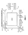
- the apparatus 10 includes a light source for producing a beam of light for writing onto a media 12.
- the light source is a laser 14, which produces a writing light beam 16, which is directed to a rotating polygon 18 having a plurality of mirror facets 20 for reflecting of the light beam onto a writing path 22 having a starting point A and an ending point B.
- an acoustic optical modulator 24 and attenuator 26 are used to provide digital data for writing of images onto the media 12.
- An f- ⁇ lens 28 is provided for properly focusing of the beam onto the writing plane 30 over which the photosensitive media 12 passes.
- a controller 31 having appropriate circuit boards in conjunction with a computer 33 is provided for controlling operation of apparatus 10 as is customarily done in similar type devices.
- the photosensitive media 12 is photographic paper.
- the photosensitive media 12 may be any other type of media on which the scanning light beam may be used for writing.
- photographic film, thermal paper and sharable surface used in electrostatic writing are examples of any other type of media on which the scanning light beam may be used for writing.
- a pair of detectors 32,34 are provided in the writing path 22 of the scanning light beam 16 spaced apart a fixed distance D.
- the detectors 32,34 are positioned after point A where the lighting beam first starts its scanning, but prior to the actual line start position C used for initiating writing onto the media 12.
- the detectors 32,34 each comprise a photodiode, which produce a signal in response to the scanning light beam 16 passing thereover.
- the two detectors 32,34 are provided in the same supporting structure so that the distance D can be precisely controlled, which plays an important element in determining the line start position C for initiating writing onto the photosensitive media 12.
- the photodetectors 32,34 are provided in a single SPOT-2DM1 detector, which may be purchased from UDT Sensors, Inc. However, it is to be understood that detectors 32,34 may be of any desired construction or manufacture so long as they are capable of producing the appropriate signals in response to the scanning passing thereover as discussed later herein.
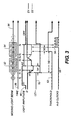
- FIG. 2 there is illustrated in diagrammatic fashion detectors 32,34 and how the scanning light beam 16 passes thereover and the various signals produced.
- the scanning light beam 16 starts at point A and travels in the direction indicated by arrow 36 across detectors 32,34.
- the circles indicated by T0-T9 represent the position and intensity of the beam as it passes detectors 32,34.
- the time line 38 merely represents the timing sequence of the scanning beam 16 as it passes detectors 32,34 along writing path 22.
- Line 40 indicates the amplitude of the light beam as it starts from point A as it progresses by the detectors 32,34.
- Lines 42,44 each represent the output voltage of each of detectors 32,34, respectively, in relationship to the light beam 16 traveling along writing path 22.
- the two lines 42,44 use the same zero reference for the output voltage.
- the voltage output of detector 32 increases from approximately T1 to a maximum at point at T2 while the output voltage of detector 34 is zero at T2.
- the voltage output of detector 32 begins to decrease.
- the voltage output of detector 34 begins to increase in response to the scanning light beam 16.
- the two lines 42,44 cross. This cross-over represents that the output voltage of both detectors 32,34 are the same.
- a line start signal is generated. It is to be understood that the determining of when the line signal based on the cross-over point 45 is generated can be accomplished in any desired manner.
- a simple comparator in controller 31 is used for comparing the signals of the outputs of detectors 32,34, thus when the two signals are substantially the same, an output signal 49 is produced. This is used to begin line start at point C. However, as indicated by line 40, a short time period after point 46, the power to the scanning light beam 16 is turned off and then turned back on at point C as determined by a predetermined time period T, which has been preselected, which is based on output signal 49. Because the detectors 32,34 are fixed in relationship to each other, the point 46 at which the voltage output signal of the detectors cross will be substantially at the same point each time the scanning light beam 16 is passed over the detectors.
- a line signal start which can be reliably repeated for use in determining the point for initiating lighting of the laser light beam as indicated by point C.
- the laser at point C, is turned on to the appropriate level and the appropriate digital data is fed through the AOM 24 for writing on media 12. It is, of course, understood that the laser light beam 16 may be turned on just prior to the time point C, the time at which digital data is provided for modulating of the light beam 16 and actual writing commences.
- Fig. 3 there is illustrated a diagrammatic representation similar to Fig. 2, like numerals indicating like parts and sequences.
- Fig. 3 illustrates how the intensity of the scanning light beam 62 can be monitored and controlled accurately during each scan and at the writing plane 30 of the media 12.
- the output signal begins to increase in amplitude as indicated by numeral 53.
- the output signal being directly related to the power level of the laser 14, thus the power level of laser can be readily determined. If the detector was previously calibrated to a standard source, the absolute power level of the laser could be determined.
- a signal LE1 is generated using a comparative circuit provided in controller 31.
- a control circuit also provided in controller 31, senses the LE1 signal and the intensity of light beam 16 is changed to an amplitude A2 at a time delay of Td1 after the circuit senses that threshold VT has been reached.
- a track and hold circuit is provided in controller 31 for monitoring the voltage of detector 32 and holding it a certain length of time after a predetermined time period Td2 after VT. By this time, the amplitude of the laser 14 has been lowered to amplitude A2.
- the amplitude of the second detector 34 is captured which can be compared with the power measurement levels previously obtained for the scanning light beam 16, and if power measurement level has changed, appropriate control of the light beam 16 may be adjusted. For example, if over time the measured amplitude of the laser has been reduced, the power to the laser 14 is increased appropriately to the desired power level. If the measured power level, as obtained by the output signal of sensor 34, is too high, appropriate reduction in power level is made.
- the present invention can automatically take power measurements during each scan, compare it to prescribed limits and appropriate adjustments may be made.
- the output current of the detectors was converted to a voltage and monitored.
- the present invention is not so limited.
- a different output parameter of the detectors 32,34 may be monitored, for example, but not by way of limitation, the output current of the detectors may be monitored directly.
- the line start signal can be generated as previously discussed.
- the present invention is not limited with respect to the relation that the voltage (or current) of the detectors may be the same.
- the voltage of the second detector is one-half of the first voltage, some other relationship can be used for determining the line start signal.
Landscapes
- Engineering & Computer Science (AREA)
- Physics & Mathematics (AREA)
- General Physics & Mathematics (AREA)
- Optics & Photonics (AREA)
- General Engineering & Computer Science (AREA)
- Theoretical Computer Science (AREA)
- Signal Processing (AREA)
- Multimedia (AREA)
- Facsimile Scanning Arrangements (AREA)
- Mechanical Optical Scanning Systems (AREA)
- Laser Beam Printer (AREA)
- Exposure Or Original Feeding In Electrophotography (AREA)
- Lasers (AREA)
- Optical Recording Or Reproduction (AREA)
Applications Claiming Priority (2)
| Application Number | Priority Date | Filing Date | Title |
|---|---|---|---|
| US218508 | 1994-03-25 | ||
| US09/218,508 US6208370B1 (en) | 1998-12-22 | 1998-12-22 | Method and apparatus for determining the starting position and the power of a scanning light beam to be used in writing on a media |
Publications (2)
| Publication Number | Publication Date |
|---|---|
| EP1014145A2 true EP1014145A2 (de) | 2000-06-28 |
| EP1014145A3 EP1014145A3 (de) | 2001-10-31 |
Family
ID=22815410
Family Applications (1)
| Application Number | Title | Priority Date | Filing Date |
|---|---|---|---|
| EP99204236A Withdrawn EP1014145A3 (de) | 1998-12-22 | 1999-12-10 | Verfahren und Vorrichtung zur Bestimmung der Startposition und der Intensität eines Abtastlichtstrahls zum Schreiben auf einen Aufzeichnungsträger |
Country Status (4)
| Country | Link |
|---|---|
| US (1) | US6208370B1 (de) |
| EP (1) | EP1014145A3 (de) |
| JP (1) | JP2000187169A (de) |
| CN (1) | CN1259682A (de) |
Cited By (3)
| Publication number | Priority date | Publication date | Assignee | Title |
|---|---|---|---|---|
| EP1293842A1 (de) * | 2001-07-19 | 2003-03-19 | Ricoh Company | Verfahren und Vorrichtung zur Bilderzeugung mit verbesserter Justage der ersten Druckstelle einer Bildaufzeichnung |
| WO2005045751A1 (en) * | 2003-10-31 | 2005-05-19 | Hewlett-Packard Development Company L.P. | Laser scanning apparatuses, laser scanning methods and article of manufacture |
| CN110798589A (zh) * | 2019-10-22 | 2020-02-14 | 苏州凸现信息科技有限公司 | 一种基于办公自动化的智能工作扫描装置 |
Families Citing this family (2)
| Publication number | Priority date | Publication date | Assignee | Title |
|---|---|---|---|---|
| US6344866B1 (en) * | 1999-04-01 | 2002-02-05 | Toshiba Tec Kabushiki Kaisha | Light beam scanner unit with passing position and power control and image forming apparatus |
| US20050134679A1 (en) * | 2003-12-04 | 2005-06-23 | Paterson Robert L. | Margin registration of a scan line in an electrophotographic printer |
Family Cites Families (17)
| Publication number | Priority date | Publication date | Assignee | Title |
|---|---|---|---|---|
| JPS54161983A (en) | 1978-06-12 | 1979-12-22 | Canon Inc | Temperature compensating circuit of photometric circuit |
| US4386272C1 (en) * | 1978-07-07 | 2001-02-06 | Pitney Bowes Inc | Apparatus and method for generating images by producing light spots of different sizes |
| US4355860A (en) * | 1980-09-29 | 1982-10-26 | Xerox Corporation | Double pass scanning system |
| JPS5845523A (ja) | 1981-09-11 | 1983-03-16 | Olympus Optical Co Ltd | 測光回路 |
| JPS58127108A (ja) * | 1982-01-26 | 1983-07-28 | Fuji Xerox Co Ltd | 光ビ−ム走査装置の走査位置検出装置 |
| JPS5946521A (ja) | 1982-09-08 | 1984-03-15 | Canon Inc | 測光回路 |
| FR2542511B1 (fr) | 1983-03-09 | 1986-12-19 | Lecoy Pierre | Procede et dispositif de regulation de la puissance lumineuse de diodes laser |
| JPS6283625A (ja) | 1985-10-08 | 1987-04-17 | Shimadzu Corp | 光パワ−メ−タ |
| JPH0361966A (ja) | 1989-07-31 | 1991-03-18 | Ricoh Co Ltd | 半導体レーザの出力制御装置 |
| JPH03276782A (ja) | 1990-03-27 | 1991-12-06 | Matsushita Electric Ind Co Ltd | パルス光源 |
| JP2956195B2 (ja) * | 1990-10-25 | 1999-10-04 | ブラザー工業株式会社 | 光ビームの変調・走査装置 |
| JPH04329512A (ja) * | 1991-04-30 | 1992-11-18 | Fuji Xerox Co Ltd | 画像記録装置 |
| US5357106A (en) * | 1993-10-01 | 1994-10-18 | Xerox Corporation | Sensor for detecting beam position and start of scan position |
| JPH07164673A (ja) | 1993-12-13 | 1995-06-27 | Minolta Co Ltd | レーザ駆動装置 |
| US5822343A (en) | 1994-08-26 | 1998-10-13 | Psc Inc. | Operating and control system for lasers useful in bar code scanners |
| EP0773461B1 (de) * | 1995-11-09 | 2005-04-27 | Kabushiki Kaisha Toshiba | Verfahren und Vorrichtung zur Mehrstrahlabtastung |
| GB2312114B (en) * | 1996-04-09 | 2000-03-29 | Icg Ltd | Apparatus for and method of controlling an image recording device |
-
1998
- 1998-12-22 US US09/218,508 patent/US6208370B1/en not_active Expired - Fee Related
-
1999
- 1999-12-10 EP EP99204236A patent/EP1014145A3/de not_active Withdrawn
- 1999-12-15 JP JP11356232A patent/JP2000187169A/ja active Pending
- 1999-12-22 CN CN99126527A patent/CN1259682A/zh active Pending
Cited By (5)
| Publication number | Priority date | Publication date | Assignee | Title |
|---|---|---|---|---|
| EP1293842A1 (de) * | 2001-07-19 | 2003-03-19 | Ricoh Company | Verfahren und Vorrichtung zur Bilderzeugung mit verbesserter Justage der ersten Druckstelle einer Bildaufzeichnung |
| US6847390B2 (en) | 2001-07-19 | 2005-01-25 | Ricoh Company, Ltd. | Method and apparatus for image forming capable of effectively adjusting an image recording start position |
| WO2005045751A1 (en) * | 2003-10-31 | 2005-05-19 | Hewlett-Packard Development Company L.P. | Laser scanning apparatuses, laser scanning methods and article of manufacture |
| US7693197B2 (en) | 2003-10-31 | 2010-04-06 | Hewlett-Packard Development Company, L.P. | Laser scanning apparatuses, laser scanning methods and article manufacture |
| CN110798589A (zh) * | 2019-10-22 | 2020-02-14 | 苏州凸现信息科技有限公司 | 一种基于办公自动化的智能工作扫描装置 |
Also Published As
| Publication number | Publication date |
|---|---|
| US6208370B1 (en) | 2001-03-27 |
| CN1259682A (zh) | 2000-07-12 |
| EP1014145A3 (de) | 2001-10-31 |
| JP2000187169A (ja) | 2000-07-04 |
Similar Documents
| Publication | Publication Date | Title |
|---|---|---|
| CA1318802C (en) | Scanning optical apparatus | |
| CA2018497C (en) | Pel placement correction in the scan dimension of a multiple beam laser scanning system | |
| US6208370B1 (en) | Method and apparatus for determining the starting position and the power of a scanning light beam to be used in writing on a media | |
| US5617132A (en) | Method and apparatus for adjusting the pixel placement in a raster output scanner | |
| KR100340158B1 (ko) | 화상 형성 장치 및 방법 | |
| CN102262516B (zh) | 信息处理设备、打印设备和信息处理方法 | |
| US6693658B2 (en) | Light beam scanning apparatus | |
| JPH01240072A (ja) | 画像記録装置 | |
| JPS5975760A (ja) | 光走査方式 | |
| US7119875B2 (en) | Apparatus for forming pattern | |
| US20010038444A1 (en) | Detection of pitch variations in lenticular material | |
| JPH11237307A (ja) | レーザービーム射出光学ユニットから射出されるレーザービームのピント位置測定方法およびピント位置調整方法 | |
| JPS58100118A (ja) | レ−ザビ−ム走査装置 | |
| US6727972B2 (en) | Detection of pitch variations in lenticular material | |
| JPH04219714A (ja) | 書き出し位置調整方法 | |
| EP1746466B1 (de) | Optische Schreibvorrichtung, optisches Schreibverfahren und Bilderzeugungsvorrichtung | |
| JPH06235873A (ja) | 走査光学装置 | |
| US6717649B2 (en) | Detection of pitch variations in lenticular material | |
| JPS62170986A (ja) | 電子写真式プリンタ | |
| JP2009128484A (ja) | 光学走査装置及びこれを含む画像形成装置 | |
| JPH02106715A (ja) | 多点同期方式の光走査装置 | |
| JPH01259316A (ja) | 光ビーム走査装置 | |
| JPH0894949A (ja) | 画像形成装置 | |
| JPH0722321B2 (ja) | レ−ザビ−ム記録装置 | |
| JP2003057583A (ja) | 光走査装置 |
Legal Events
| Date | Code | Title | Description |
|---|---|---|---|
| PUAI | Public reference made under article 153(3) epc to a published international application that has entered the european phase |
Free format text: ORIGINAL CODE: 0009012 |
|
| AK | Designated contracting states |
Kind code of ref document: A2 Designated state(s): AT BE CH CY DE DK ES FI FR GB GR IE IT LI LU MC NL PT SE Kind code of ref document: A2 Designated state(s): CH DE GB LI |
|
| AX | Request for extension of the european patent |
Free format text: AL;LT;LV;MK;RO;SI |
|
| PUAL | Search report despatched |
Free format text: ORIGINAL CODE: 0009013 |
|
| AK | Designated contracting states |
Kind code of ref document: A3 Designated state(s): AT BE CH CY DE DK ES FI FR GB GR IE IT LI LU MC NL PT SE |
|
| AX | Request for extension of the european patent |
Free format text: AL;LT;LV;MK;RO;SI |
|
| 17P | Request for examination filed |
Effective date: 20020328 |
|
| AKX | Designation fees paid |
Free format text: CH DE GB LI |
|
| 17Q | First examination report despatched |
Effective date: 20020816 |
|
| STAA | Information on the status of an ep patent application or granted ep patent |
Free format text: STATUS: THE APPLICATION IS DEEMED TO BE WITHDRAWN |
|
| 18D | Application deemed to be withdrawn |
Effective date: 20021230 |