EP1013318A2 - Bindungsplattenanordnung und Skibindung - Google Patents
Bindungsplattenanordnung und Skibindung Download PDFInfo
- Publication number
- EP1013318A2 EP1013318A2 EP99811179A EP99811179A EP1013318A2 EP 1013318 A2 EP1013318 A2 EP 1013318A2 EP 99811179 A EP99811179 A EP 99811179A EP 99811179 A EP99811179 A EP 99811179A EP 1013318 A2 EP1013318 A2 EP 1013318A2
- Authority
- EP
- European Patent Office
- Prior art keywords
- ski
- binding
- binding plate
- guide
- carriage
- Prior art date
- Legal status (The legal status is an assumption and is not a legal conclusion. Google has not performed a legal analysis and makes no representation as to the accuracy of the status listed.)
- Withdrawn
Links
- 230000027455 binding Effects 0.000 title claims abstract description 111
- 238000009739 binding Methods 0.000 title claims abstract description 111
- 229920001971 elastomer Polymers 0.000 claims description 14
- 239000000806 elastomer Substances 0.000 claims description 14
- 238000013459 approach Methods 0.000 claims description 11
- 239000002184 metal Substances 0.000 claims description 7
- 230000006835 compression Effects 0.000 claims description 6
- 238000007906 compression Methods 0.000 claims description 6
- 238000013461 design Methods 0.000 claims description 5
- 238000006073 displacement reaction Methods 0.000 claims description 3
- 210000003128 head Anatomy 0.000 description 12
- 239000000463 material Substances 0.000 description 5
- 239000000725 suspension Substances 0.000 description 5
- 229920003023 plastic Polymers 0.000 description 4
- 239000004033 plastic Substances 0.000 description 4
- 238000013519 translation Methods 0.000 description 3
- 238000005452 bending Methods 0.000 description 2
- 230000001419 dependent effect Effects 0.000 description 2
- 230000002349 favourable effect Effects 0.000 description 2
- 210000001331 nose Anatomy 0.000 description 2
- 230000035515 penetration Effects 0.000 description 2
- 230000036316 preload Effects 0.000 description 2
- 238000004904 shortening Methods 0.000 description 2
- 241000270272 Coluber Species 0.000 description 1
- 229910000639 Spring steel Inorganic materials 0.000 description 1
- 229910000831 Steel Inorganic materials 0.000 description 1
- 238000010521 absorption reaction Methods 0.000 description 1
- 230000006978 adaptation Effects 0.000 description 1
- 230000009286 beneficial effect Effects 0.000 description 1
- 238000010276 construction Methods 0.000 description 1
- 238000005520 cutting process Methods 0.000 description 1
- 230000006735 deficit Effects 0.000 description 1
- 238000011161 development Methods 0.000 description 1
- 238000004512 die casting Methods 0.000 description 1
- 230000007613 environmental effect Effects 0.000 description 1
- 230000007257 malfunction Effects 0.000 description 1
- 238000004519 manufacturing process Methods 0.000 description 1
- 238000005457 optimization Methods 0.000 description 1
- 230000000149 penetrating effect Effects 0.000 description 1
- 229920002635 polyurethane Polymers 0.000 description 1
- 239000004814 polyurethane Substances 0.000 description 1
- 230000008092 positive effect Effects 0.000 description 1
- 230000001681 protective effect Effects 0.000 description 1
- 238000000926 separation method Methods 0.000 description 1
- 239000010959 steel Substances 0.000 description 1
- 238000012549 training Methods 0.000 description 1
- XLYOFNOQVPJJNP-UHFFFAOYSA-N water Substances O XLYOFNOQVPJJNP-UHFFFAOYSA-N 0.000 description 1
Images


Classifications
-
- A—HUMAN NECESSITIES
- A63—SPORTS; GAMES; AMUSEMENTS
- A63C—SKATES; SKIS; ROLLER SKATES; DESIGN OR LAYOUT OF COURTS, RINKS OR THE LIKE
- A63C9/00—Ski bindings
- A63C9/003—Non-swivel sole plate fixed on the ski
Definitions
- the invention relates to a binding plate arrangement for ski bindings Heel holder and headboard.
- the invention also relates to a safety ski binding with a heel holder connected to the ski and one in the longitudinal direction of the Skis arranged at a distance from the heel holder, connected to the ski, wherein the headboard with a towards the ski tip against the force of spring elements is connected to the ski axially displaceably mounted sled, which on a the guide associated with the ski.
- a binding plate arrangement in which a plate carrying the binding in a front and a rear area with a Ski-connected fasteners is mounted.
- the plate has one or more to the ski protruding ribs, parallel to the longitudinal direction of the ski, in which elongated holes are trained. Pins are located in the elongated holes, which are attached to the fastening parts are moored. This allows, in addition to the simple disassembly and assembly of the plate together Binding that the ski can bend freely in the binding area. It is also a Locking the plate in the longitudinal direction of the ski is provided so that the plate is not in the Slides forward and backward, but in a defined position on the ski is positioned.
- the fastening parts can also be attached to the plate at a second location be connected to stiffen the skis in the binding area.
- Disadvantage of this Binding is that the pressure forces from the shoe to the ski via line contacts between the Pins and the elongated holes must be transferred, resulting in high loads and Material deformation at these points result. Snow can also easily freeze over accumulate between plate and ski and the function of the binding plate arrangement impair or prevent.
- a ski binding is known from DE-AS 1 578 749, in which both the Heel holder as well as the head part against the force of spring elements in the longitudinal direction of the Skis are slidable.
- the axial displaceability of both parts is for this construction entry into the binding with the ski boot required.
- the cross-section of the solution shown in AT-PS 358 446 is one about T-shaped guide rail for the headboard attached to the ski.
- a C-shaped in cross section The carriage, on which the actual headboard is attached, grips around the Guide rail on its long edges. Both the guide rail and the slide are obviously designed as sheet metal structures. Since the management area against outside is not closed, snow and ice can get into this area and the Impair function. There is also a risk of icing, which can cause that the two parts freeze together and the ski binding is no longer is functional.
- the invention has for its object a ski binding or To create binding plate arrangement that allows good guidance of the ski and a has high operational reliability.
- the flexibility of the ski should also be in the area the bond is preserved.
- a binding plate arrangement for ski bindings with heel holder and headboard is distinguished according to the invention in that one binding plate has two Fastening parts for fastening the binding plate to the ski, at least one with the Fasteners connected axial guidance and one between the fasteners of these separate sledges.
- This binding plate is also between the Carriage and a fastening part in the axial direction of the guide a range of motion provided, and the carriage is after attaching the binding plate to a ski through the Guided in such a way that the carriage only one compared to the fastening parts translational movement in the axial direction of the guide is possible.
- Binding plates For the heel holder and the headboard there are two separate ones Binding plates provided. Only one of the two has to be moved Be designed sledge. The other can be in one piece or with no freedom of movement be trained.
- the binding plates are expediently in the longitudinal direction of the ski elongated.
- the fastening parts for fastening to the ski are arranged in end areas and in between there is a carriage separate from the fastening parts.
- the headboard, or possibly the heel holder can be attached.
- the sled is in one guided with the fastening parts guided such that it after fastening of the fastening parts on the ski every twist and movement transversely to the longitudinal direction is impossible.
- a binding plate between the Carriage and a fastening part can be arranged on the ski in the longitudinal direction Freedom of movement. Thanks to this scope, the sled can be relative to the Move fasteners.
- a margin in the front binding plate is preferred, namely between the sledge and the fastening part to be arranged towards the ski tip.
- the freedom of movement is advantageously in the initial position of the slide on one side, and spring elements are arranged such that they are one-sided Counteract the force reducing the freedom of movement.
- the spring elements can do this Apply pressure or tension.
- the spring elements advantageously consist of a Space between the slide and the fastening part arranged elastomer element.
- the fastening parts are advantageously essentially the same width as that Sled or narrower than this. This allows a width of the carriage which the Optimal use of ski width.
- the fasteners are advantageous in a direction transverse to Longitudinal direction of the ski elongated. Included in every fastener expediently at least two holes for fasteners next to each other arranged. The holes are on a line transverse to the axial direction of the guide and therefore arranged transversely to the longitudinal direction of the ski. This is through the fasteners caused minimal stiffening of the ski.
- the guide can be the two Connect the fastening parts of a binding plate, but it must be under Let the load bend together with the ski.
- the binding plate arrangement is usually below conventional Bindings mountable. Because the binding plates for the heel holder and the head part are separated , they can also be integrated directly into the ski binding.
- the cross section of the slide is essentially U-shaped, the guide in the central area has a lengthwise direction of the ski extending, at a distance from the ski arranged longitudinal bar, and passes through the sled the space between the ski and the longitudinal web at least partially.
- the slide engages under the longitudinal web of the guide. In doing so, he can support himself directly or indirectly on the surface of the ski. As a result of the resulting low wing loading, favorable results result Frictional conditions, which a safe function of the axial displaceability of the Ensure headboard even under difficult environmental influences.
- the cross section of the guide rail or the longitudinal web can in principle be constant over their entire length. However, it is advantageous if the guide element a front and a rear, adjacent to the longitudinal web, in relation to the width of the Has longitudinal web enlarged attachment for connection to the ski. Thus it results a good connection of the guide rail with the ski, as the widened Fasteners a large distance between the screw holes and thus the absorption of high Enable forces and moments.
- the shoulders of the fasteners can additionally serve as stops for the sled, or for this striking Spring elements.
- the fasteners can be integrally formed with the longitudinal web or be designed as separate parts which are detachably or non-detachably connected to the longitudinal web.
- a multi-piece design of the guide element gives the advantage that for the individual parts, i.e. the longitudinal bar and the fastening parts are the most suitable for this Materials such as steel, light metal or the like can be used.
- An expedient embodiment is that the envelope contour of the Longitudinal web is essentially rectangular in cross section.
- the three the ski facing surfaces form the lateral guidance and the support of the slide when facing away from the surface of the ski and attacking the head part of the ski binding Powers.
- the envelope contour of the longitudinal web is or the guide rail, essentially designed as a circular segment in cross section, wherein the curved side of the longitudinal web faces the ski or the sled.
- a segment of a circle can, for example, be cut longitudinally from a cylindrical rod getting produced.
- the cross-section of the longitudinal web can also be variable Have rounding radii and, for example, as part of a prismatic body be oval-shaped cross section.
- the sled has two essentially parallel legs and a web connecting the legs, wherein the thickness of the web is essentially the distance of the longitudinal web from the Surface of the ski corresponds.
- the carriage cannot be guided only in that perpendicular to the surface of the ski, but also in both perpendicular to the surface of the Skiing directions absorb considerable forces and moments.
- To the End faces of the legs of the carriage can then be any commercially available one in principle Headboard or a commercially available heel holder can be attached.
- any known elements can be used as spring elements become.
- An advantageous embodiment is that the spring elements as Elastomer pads are formed.
- Such elastomer pads have a very high elasticity on and can for example consist of polyurethane or the like.
- elastomer pads are not directly enclosed on all sides, but rather that there are free spaces into which the elastomer material deforms elastically can.
- the spring elements can expediently also be designed as compression springs.
- Compression springs enable a very compact design and can absorb high forces. By combining several spring elements, you can also choose from one linear characteristic deviating spring characteristics can be achieved.
- the desired mechanical properties of the suspension depend on the driving style, Height and weight of the driver as well as the snow and slope conditions dependent. It is therefore advantageous if at least one adjusting member for changing the Spring characteristic of the spring elements is provided. This is an individual, optimal Adaptation to the respective conditions possible.
- the adjusting member can, for example, as Set screw designed to increase or decrease the preload and thus the Characteristics of the spring elements can be changed.
- the sled can be supported directly on and on the surface of the ski be axially displaceable.
- the sliding properties of the slide are very good strongly dependent on the sliding properties of the ski's top layer.
- it is appropriate that between the ski and the guide element in the A sliding plate is arranged in the region of the longitudinal web.
- Such a sliding plate can for example made of plastic or sheet metal.
- the slide plate advantageously has the side one Sliding area covering the sliding area, protruding from the surface of the ski Approaches on.
- the approaches can prevent snow and ice from entering the Prevent the sliding area of the slide to a large extent.
- these approaches can also be formed on a cover slipped over the carriage.
- the cover on its longitudinal edges against the surface of the ski has outstanding approaches.
- Such approaches can for example be bent through 90 ° Edges.
- the Slide plate and the cover expediently substantially perpendicular to Surface of the ski on the lugs, the lateral distance between the lugs so it is coordinated that the approaches interlock like a box. Since the Preferably overlap approaches, creates a kind of labyrinth seal that prevents penetration prevented by disruptive elements.
- any choice of material is possible. However, it is very beneficial if the slide is made of plastic. Plastics generally show a lot good sliding properties.
- the guide rail (4c) is advantageously a deformed, profiled sheet metal part. This allows a high force absorbing and yet elastically deformable version of the Rail, e.g. a spring steel is used for this.
- the ski binding shown in FIG. 1 shows a ski 1 with a heel holder 2 and a head part 3.
- the guide element 4 has for this purpose at its ends a front fastening part 4a and at its opposite end of a rear fastening part 4b.
- a longitudinal web or a guide rail 4c in Longitudinal direction of the ski 1.
- a sled, designated in total by 6, surrounds the longitudinal bar 4c on three sides and is thus guided on this.
- the dash-dotted line in Fig. 1 Head part 3 of the ski binding is screwed to threaded holes 6a of the slide 6.
- the head part 3 can thus be moved together with the slide 6 in the longitudinal direction of the ski 1.
- the heel holder 2 is fastened to the ski 1 via an intermediate piece 7.
- the amount of The intermediate piece 7 is approximately the thickness of the guide element 4 or of the slide 6 customized. Due to different heights of the supports in the area of the heel holder 2 and of the head part 3 can the starting position of the ski boot in the binding, or Tilt angle between ski boot and ski can be set.
- spring elements 8 are arranged between the front end of the carriage 6 and the carriage 6 facing shoulders 4d of the front fastening part 4a. These spring elements 8 are designed as elastomer pads. The sledge 6 can thus only be moved against the force of the spring elements 8 in the direction of the ski tip become. In its initial position shown in Fig. 1, the carriage 6 is replaced by the Spring elements 8 pushed against shoulders 4e of the rear fastening part 4b.
- ski binding is one of the two Spring elements replaced by a compression spring 10.
- the function of the device is exactly the same as in the embodiment shown in FIG. 1.
- adjusting member 11 is provided in the area of Compression spring 10 axially penetrating the front fastening part 4a. About the adjustment 11 can the preload of the compression springs 10 and thus also the spring characteristic are set.
- Fig. 5 is also the rectangular cross-section longitudinal web 4c with the im Cross-section of U-shaped carriage surrounding the longitudinal web 4c on three sides 6 can be seen.
- a slide plate 12 On the side of the slide 6 facing the ski is a slide plate 12 firmly screwed together with the guide element on the ski.
- the Carriage 6 can thus be supported on the sliding plate 12 and slide on it.
- the sliding plate 12 and the cover 13 have angled at their longitudinal edges Approaches 12a, 13a, which interlock like a box and thus in Sliding area of the slide 6 on the guide element 4 provides protection against penetration of snow and foreign bodies.
- FIG. 6 shows a further embodiment of the ski binding according to the invention with a Longitudinal web 14a of a guide element 14, which in cross section essentially as Circular segment is formed.
- a correspondingly trained slide 16 is with a concave recess.
- Figure 7a is a binding plate according to the principle explained with reference to Figures 1 to 6 shown. It has a front fastening part 4a and a rear fastening part 4b, which are connected to each other with a web 4c.
- the web 4c is by means of screws 17th attached to the fasteners and sits snugly in orthogonal recesses in the Fastening parts 4a and 4b.
- a base plate or a slide 6 is with the web 4c guided and can only be moved in the longitudinal direction of the web.
- Carriage 6 and front fastening part 4a provided a space in which a Elastomer strip 18 is used fully.
- the spring force of the elastomer strip 18 acts one force reducing the gap.
- the elasticity of the elastomer strip can by the choice of material, the choice of its dimensions and e.g. by bringing in Openings in the strips 18 and their orientation can be influenced.
- the fastening parts 4a and 4b are in the direction transverse to the longitudinal axis and Binding plate longitudinal axis elongated.
- the contact surface is as short as possible, so that the Ski flexibility is hampered as little as possible.
- the holes 5 'for the mounting screws 5 are for the same reason arranged on an axis transverse to the longitudinal axis of the ski.
- the binding plate is through a sliding plate 12 to the ski and a cover 13th covered for binding.
- the cover 13 and the slide plate 12 are laterally around the Carriage 6 and the fastening parts 4a, 4b are bent around like grooves. They overlap similar to that shown in Figure 5, to form ice between mutually movable parts to prevent the binding plate.
- the approaches differ from those in FIG. 5 shown short on the slide plate and long on the cover to a to achieve greater flexibility of the sliding plate.
- the cover 13 are Fastening areas 19 except those for attaching a binding to the Mark the binding plate in suitable areas. In the edge of these recesses 19 is in each case cut out a tooth 20 and bent perpendicular to the cover 13. Each tooth 20 sits when the binding is assembled in a bore 21 in the carriage 6 and thus secures the Cover before a shift in relation to the slide 6.
- the carriage 6 with the guide rail 4c is shown in cross section.
- the carriage 6 is cast or extruded from a plastic.
- the guide rail 4c is made from a folded sheet metal strip.
- the sheet metal strip is essentially U-shaped or W-shaped. In any case, it has side and bottom sliding surfaces, which with a Interact recess in the carriage 6.
- the web 4c interrupted.
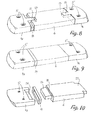
- Two profile rails similar to the guide rail 4c in Figure 7b can also be pushed into each other, with one on one and the other on the other Fastening part 4a, or 4b is attached. As shown in Figure 8, they are the two Fastening parts 4a, 4b separated from each other.
- the guide for the carriage only from a nose 22 on the two fastening parts 4a and 4b. This also allows a shortening of the distance between the fastening parts 4a, 4b as a result of Deflection of the ski. Through these measures, the ski is also over in its flexibility the length of the individual binding plates is not significantly affected.
- Figures 9 and 10 show a further embodiment in which the Elastomer suspension 24 at the same time a seal between slide 6 and fastening part 4a forms.
- the binding plate according to Figure 9 is disassembled in Figure 10, with only one of the fastening parts and of the Shown below.
- the joints between the fastening parts 4a, 4b and Carriages 6 are straight.
- the fastening parts 4a, 4b form on the carriage 6 facing side a kind of trough 25, which against the carriage 6 and the bottom is open.
- Extensions 26, 27 are formed on the slide 6 and fit into the grooves 25 are.
- the trough 25 prevents the extension 26 sitting therein and thus the slide 6 the bottom of the gutter facing the binding before removing it from the ski, and through the Channel walls before sliding sideways.
- the extensions 26, 27 are slightly rounded on their underside so that the Fastening parts 4a, 4b move together with the ski and in relation to the slide 6 can take an angle without jamming the carriage. From the same The bottom of the channel 25 is curved. As a result, it lies with a line contact on the slide 6. The greater the sag of the ski, the greater this line contact closer to the joint between fastening part 4a, 4b and slide 6.
- the trough 25 in the fastening part 4a is around the necessary freedom of movement Longitudinal direction of the ski extend into it longer than the extension 26 in the starting position can. Since the elastomer suspension 24 between the fastening part 4a and the base plate 6 is arranged, the extension 26, which is held in the fastening part 4a, nevertheless be longer than the opposite extension 27. So that the elastomer suspension 24 does not inadvertently removed from their place between base plate 6 and fastening part 4a can be formed as a ring. The extension 26 extends through the ring and This secures the suspension 24. For example, a groove 28 can be provided in the extension 26 be exempt.
Landscapes
- Connection Of Plates (AREA)
- Footwear And Its Accessory, Manufacturing Method And Apparatuses (AREA)
Abstract
Description
Claims (14)
- Bindungsplattenanordnung für Skibindungen mit Fersenhalter und Kopfteil, bei welcher eine Bindungsplatte zwei Befestigungsteile (4a, 4b) zur Befestigung der Bindungsplatte am Ski (1), zwischen den Befestigungsteilen (4a, 4b) einen von diesen getrennten Schlitten (6), und wenigstens eine axiale Führung (4c, 22, 25) zur Führung des Schlittens (6) gegenüber den Befestigungsteilen (4a,4b) aufweist,dadurch gekennzeichnet, dass für den Fersenhalter und das Kopfteil zwei voneinander getrennte Bindungsplatten vorgesehen sind.dass bei dieser Bindungsplatte zwischen dem Schlitten (6) und einem Befestigungsteil (4a,4b) in Achsrichtung der Führung (4c, 22, 25) ein Bewegungsspielraum vorgesehen ist, unddass der Schlitten (6) nach Befestigung der Bindungsplatte an einem Ski (1) durch die Führung derart geführt ist, dass dem Schlitten (6) gegenüber den Befestigungsteilen (4a,4b) lediglich eine translatorische Bewegung in Achsrichtung der Führung (4c, 22, 25) möglich ist,
- Bindungsplattenanordung nach Anspruch 1, dadurch gekennzeichnet, dass der Bewegungsspielraum in Grundstellung der Grundplatte (6) einseitig vorliegt, und dass Federmittel (8,10,18,24) derart angeordnet sind, dass sie einer diesen einseitigen Bewegungsspielraum verkleinernden Kraft entgegenwirken.
- Bindungsplattenanordung nach Anspruch 1 oder 2, dadurch gekennzeichnet, dass in jedem Befestigungsteil (4a,4b) wenigstens zwei Löcher (5') für Befestigungselemente (5) in einer Richtung quer zur Achsrichtung der Führung (4c, 22, 25) nebeneinander angeordnet sind.
- Bindungsplattenanordung nach einem der Ansprüche 1 bis 3, dadurch gekennzeichnet, dass eine Führungsschiene (4c) den Abstand zwischen beiden Befestigungsteile (4a,4b) einer Bindungsplatte überbrückt und sich unter Belastung zusammen mit dem Ski biegen lässt.
- Bindungsplattenanordung nach einem der Ansprüche 1 bis 4, dadurch gekennzeichnet, dass die beiden Befestigungsteile (4a,4b) einer Bindungsplatte getrennt sind.
- Bindungsplattenanordung nach Anspruch 5, dadurch gekennzeichnet, dass an jedem Befestigungsteil (4a,4b) eine separate Führung vorgesehen ist, welche Führungen (22, 25) voneinander getrennt und in Achsrichtung relativ zueinander einander beweglich sind.
- Bindungsplattenanordung nach einem der Ansprüche 1 bis 6, dadurch gekennzeichnet, dass beide Befestigungsteile (4a,4b) identisch ausgebildet sind.
- Skibindung mit einem Fersenhalter (2) und einem in einem Abstand in Längsrichtung der Bindung getrennt vom Fersenhalter (2) mit einem Ski (1) zu verbindenden Kopfteil (3), wobei das Kopfteil (3) mit einem vom Fersenhalter (2) unabhängigen Schlitten (6) verbunden ist, der in Längsrichtung mit einer Führung (4) geführt ist, dadurch gekennzeichnet, dass die Führung (4) an einem vorderen und einem rückwärtigen Befestigungsteil (4a, 4b) und der Schlitten (6) zwischen diesen angeordnet ist.
- Skibindung mit einem mit dem Ski (1) verbundenen Fersenhalter (2) und einem in Längsrichtung des Skis (1) im Abstand und getrennt vom Fersenhalter (2) mit dem Ski (1) zu verbindenden Kopfteil (3), wobei das Kopfteil (3) mit einem in Richtung der Skispitze gegen die Kraft von Federelementen (8,10,18,24) gegenüber dem Ski (1) axial verschiebbar gelagerten Schlitten (6) verbunden ist, der auf einer mit dem Ski (1) verbundenen Führung (4,14) geführten wird, dadurch gekennzeichnet, dass der Schlitten (6) im Querschnitt im Wesentlichen U-förmig ausgebildet ist, die Führung (4, 14) im mittleren Bereich einen in Längsrichtung des Skis (1) verlaufenden, im Abstand vom Ski (1) angeordneten Längssteg (4c, 14a) aufweist, und der Schlitten (6, 16) den Zwischenraum zwischen dem Ski (1) und dem Längssteg (4c, 14a) wenigstens teilweise durchsetzt.
- Skibindung oder Bindungsplattenanordnung nach einem der Ansprüche 1 bis 9, dadurch gekennzeichnet, dass die Federelemente als Elastomerpolster (8) ausgebildet sind.
- Skibindung oder Bindungsplattenanordnung nach einem der Ansprüche 1 bis 9, dadurh gekennzeichnet, dass die Federelemente als Druckfedern (10) ausgebildet sind, und dass wenigstens ein Verstellorgan (11) zum Verändern der Federcharakteristik der Federelemente vorgesehen ist.
- Skibindung oder Bindungsplattenanordnung nach einem der Ansprüche 1 bis 11, dadurch gekennzeichnet, dass skiseitig des Schlittens (6) eine Gleitplatte (12) angeordnet ist.
- Skibindung oder Bindungsplattenanordnung nach Anspruch 12, dadurch gekennzeichnet, dass die Gleitplatte (12) den seitlichen Verschiebebereich des Schlittens abdeckende, von der Oberfläche des Skis wegragende Ansätze (12a) aufweist, dass der Schlitten (6) auf seiner dem Ski abgewandten Seite mit einer Abdeckung (13) verbunden ist, welche an ihren Längskanten gegen die Oberfläche des Skis ragende Ansätze (13a) aufweist, und dass diese Ansätze (12a,13a) schachtelartig ineinander eingreifen.
- Skibindung oder Bindungsplattenanordnung nach einem der Ansprüche 1 bis 13 in Verbindung mit Anspruch 4, dadurch gekennzeichnet, dass die Führungsschiene (4c) als verformtes, profiliertes Blechteil ausgebildet ist.
Applications Claiming Priority (2)
| Application Number | Priority Date | Filing Date | Title |
|---|---|---|---|
| CH257098 | 1998-12-22 | ||
| CH257098 | 1998-12-22 |
Publications (2)
| Publication Number | Publication Date |
|---|---|
| EP1013318A2 true EP1013318A2 (de) | 2000-06-28 |
| EP1013318A3 EP1013318A3 (de) | 2002-09-25 |
Family
ID=4236776
Family Applications (1)
| Application Number | Title | Priority Date | Filing Date |
|---|---|---|---|
| EP99811179A Withdrawn EP1013318A3 (de) | 1998-12-22 | 1999-12-20 | Bindungsplattenanordnung und Skibindung |
Country Status (1)
| Country | Link |
|---|---|
| EP (1) | EP1013318A3 (de) |
Cited By (1)
| Publication number | Priority date | Publication date | Assignee | Title |
|---|---|---|---|---|
| AT412449B (de) * | 2003-01-20 | 2005-03-25 | Martin Dipl Ing Breuer-Bono | Schibindung, insbesondere tourenschibindung |
Citations (3)
| Publication number | Priority date | Publication date | Assignee | Title |
|---|---|---|---|---|
| DE1578749A1 (de) | 1962-06-18 | 1971-07-01 | ||
| AT358446B (de) | 1978-02-20 | 1980-09-10 | Tyrolia Freizeitgeraete | Sicherheitsskibindung |
| US5671939A (en) | 1995-03-10 | 1997-09-30 | Pineau; David G. | Binding mount assembly for an alpine ski |
Family Cites Families (7)
| Publication number | Priority date | Publication date | Assignee | Title |
|---|---|---|---|---|
| FR2639242B1 (fr) * | 1988-11-18 | 1990-12-28 | Rossignol Sa | Ensemble perfectionne pour la pratique du ski, constitue par une chaussure et un ski |
| DE9102551U1 (de) * | 1991-03-04 | 1991-05-23 | Blizzard Ges.m.b.H., Mittersill | Ski |
| WO1992022361A1 (en) * | 1991-06-17 | 1992-12-23 | Trimble & Co., Inc. | Ski binding block |
| FR2688410B1 (fr) * | 1992-03-10 | 1994-05-06 | Rossignol Sa Skis | Dispositif pour le montage sur un ski d'une fixation de securite, comprenant une butee et une talonniere independantes l'une de l'autre. |
| FR2693379B1 (fr) * | 1992-07-09 | 1994-09-23 | Salomon Sa | Ski nervure muni d'un support. |
| AT399660B (de) * | 1992-12-21 | 1995-06-26 | Tyrolia Freizeitgeraete | Ski |
| FR2721526B1 (fr) * | 1994-06-22 | 1996-08-23 | Rossignol Sa | Planche de glisse pourvue d'une plaque de surélévation des fixations de la chaussure. |
-
1999
- 1999-12-20 EP EP99811179A patent/EP1013318A3/de not_active Withdrawn
Patent Citations (3)
| Publication number | Priority date | Publication date | Assignee | Title |
|---|---|---|---|---|
| DE1578749A1 (de) | 1962-06-18 | 1971-07-01 | ||
| AT358446B (de) | 1978-02-20 | 1980-09-10 | Tyrolia Freizeitgeraete | Sicherheitsskibindung |
| US5671939A (en) | 1995-03-10 | 1997-09-30 | Pineau; David G. | Binding mount assembly for an alpine ski |
Cited By (1)
| Publication number | Priority date | Publication date | Assignee | Title |
|---|---|---|---|---|
| AT412449B (de) * | 2003-01-20 | 2005-03-25 | Martin Dipl Ing Breuer-Bono | Schibindung, insbesondere tourenschibindung |
Also Published As
| Publication number | Publication date |
|---|---|
| EP1013318A3 (de) | 2002-09-25 |
Similar Documents
| Publication | Publication Date | Title |
|---|---|---|
| DE3153702C2 (de) | Skibindung | |
| DE4124965B4 (de) | Plattenförmige Dämpfungsvorrichtung für eine Schibindung | |
| AT402900B (de) | Kupplungsvorrichtung zwischen schi und schischuh mit einer längenverstellvorrichtung | |
| DE69015485T2 (de) | Zusatzvorrichtung zum Ski zur Montage eines Paares Skibindungen auf dem Ski. | |
| DE4321239A1 (de) | Ski | |
| AT410638B (de) | Bindungstragplatte und brettartiges gleitgerät hierzu | |
| EP1161972A2 (de) | Gleitbrett, insbesondere Ski sowie Profilschienen-System für ein solches Gleitbrett | |
| DE29608903U1 (de) | Vorrichtung zur Aufnahme einer Skibindung auf einem Ski und mit einer derartigen Vorrichtung ausgerüsteter Ski | |
| EP0493395A1 (de) | Skischuh. | |
| DE60112190T2 (de) | Alpinski | |
| AT405139B (de) | Gleitgerät | |
| EP1297869B1 (de) | Schneegleitbrett, insbesondere Ski | |
| AT392497B (de) | Gleitstuhl, gleitplatte bzw. rippenplatte fuer schienenweichen oder -kreuzungen | |
| AT500307B1 (de) | Basisplatte für eine ski- bzw. snowboardbindung | |
| EP0878218B1 (de) | Schuhabroll- und -stützelement als Teil einer Skibindung | |
| DE69909461T2 (de) | Konstruktion eines öffnungsfähigen fahrzeugsdaches | |
| EP1013318A2 (de) | Bindungsplattenanordnung und Skibindung | |
| DE10223547B4 (de) | Ski, Verfahren zur Montage einer Skibindung an dem Ski und Verfahren zur Herstellung des Skis | |
| DE3029878A1 (de) | Dreigliedrige teleskopschiene | |
| EP0935489B1 (de) | Vorrichtung zur veränderung der seitwärtsneigung eines skischuhs auf einem ski | |
| AT401353B (de) | Vorrichtung zur seitlichen führung eines schuhs auf einem ski, insbesondere auf einem langlaufski | |
| EP0612543B1 (de) | Schwingungsdämpfungseinrichtung | |
| EP0129535A1 (de) | Einheit aus Langlaufbindung und Langlaufschuhen | |
| DE69707737T2 (de) | Montageplatte für eine Skibindung | |
| DE102008036390A1 (de) | Schneegleitbrett |
Legal Events
| Date | Code | Title | Description |
|---|---|---|---|
| PUAI | Public reference made under article 153(3) epc to a published international application that has entered the european phase |
Free format text: ORIGINAL CODE: 0009012 |
|
| AK | Designated contracting states |
Kind code of ref document: A2 Designated state(s): AT BE CH CY DE DK ES FI FR GB GR IE IT LI LU MC NL PT SE |
|
| AX | Request for extension of the european patent |
Free format text: AL;LT;LV;MK;RO;SI |
|
| PUAL | Search report despatched |
Free format text: ORIGINAL CODE: 0009013 |
|
| AK | Designated contracting states |
Kind code of ref document: A3 Designated state(s): AT BE CH CY DE DK ES FI FR GB GR IE IT LI LU MC NL PT SE |
|
| AX | Request for extension of the european patent |
Free format text: AL;LT;LV;MK;RO;SI |
|
| AKX | Designation fees paid | ||
| REG | Reference to a national code |
Ref country code: DE Ref legal event code: 8566 |
|
| STAA | Information on the status of an ep patent application or granted ep patent |
Free format text: STATUS: THE APPLICATION IS DEEMED TO BE WITHDRAWN |
|
| 18D | Application deemed to be withdrawn |
Effective date: 20030326 |