EP1010584A2 - Traversée de conduite à travers une paroi - Google Patents
Traversée de conduite à travers une paroi Download PDFInfo
- Publication number
- EP1010584A2 EP1010584A2 EP99123552A EP99123552A EP1010584A2 EP 1010584 A2 EP1010584 A2 EP 1010584A2 EP 99123552 A EP99123552 A EP 99123552A EP 99123552 A EP99123552 A EP 99123552A EP 1010584 A2 EP1010584 A2 EP 1010584A2
- Authority
- EP
- European Patent Office
- Prior art keywords
- edge
- sealing
- partial
- opening
- wall
- Prior art date
- Legal status (The legal status is an assumption and is not a legal conclusion. Google has not performed a legal analysis and makes no representation as to the accuracy of the status listed.)
- Granted
Links
Images


Classifications
-
- H—ELECTRICITY
- H02—GENERATION; CONVERSION OR DISTRIBUTION OF ELECTRIC POWER
- H02G—INSTALLATION OF ELECTRIC CABLES OR LINES, OR OF COMBINED OPTICAL AND ELECTRIC CABLES OR LINES
- H02G3/00—Installations of electric cables or lines or protective tubing therefor in or on buildings, equivalent structures or vehicles
- H02G3/22—Installations of cables or lines through walls, floors or ceilings, e.g. into buildings
-
- B—PERFORMING OPERATIONS; TRANSPORTING
- B60—VEHICLES IN GENERAL
- B60R—VEHICLES, VEHICLE FITTINGS, OR VEHICLE PARTS, NOT OTHERWISE PROVIDED FOR
- B60R16/00—Electric or fluid circuits specially adapted for vehicles and not otherwise provided for; Arrangement of elements of electric or fluid circuits specially adapted for vehicles and not otherwise provided for
- B60R16/02—Electric or fluid circuits specially adapted for vehicles and not otherwise provided for; Arrangement of elements of electric or fluid circuits specially adapted for vehicles and not otherwise provided for electric constitutive elements
- B60R16/0207—Wire harnesses
- B60R16/0215—Protecting, fastening and routing means therefor
- B60R16/0222—Grommets
Definitions
- the invention relates to a bushing for a line a wall.
- the wall is arranged, for example, in a motor vehicle and here in particular is designed as a wall between the engine compartment and the passenger compartment of a vehicle.
- Cable bundles with electrical conductors for motor vehicles as are known from DE 34 31 617 A1 and from DE 37 40 582 A1, are usually passed through a through opening penetrating the wall, in that the cable bundle and a sealing sleeve surrounding the cable bundle pass through the cable bundle in the longitudinal direction opening through ".
- threading work is laborious and expensive in terms of assembly.
- it is disadvantageous for threading that the lead-through opening must be made particularly large if one or more associated plugs are threaded through the wall in the case of electrical lines.
- the seal of the lead-through opening is particularly complex and is therefore susceptible to premature failure of the desired sealing function, which increases maintenance and repair work and the associated costs.
- the invention has for its object a technical assembly easy implementation for a line through a wall too create.
- the bushing has a wall which comprises several part walls. These partial walls are then firmly connected to one another during assembly - depending on the application, detachable or non-detachable.
- the line is first inserted transversely to the longitudinal direction of the line into the partial opening of a first partial wall which is open at the edge.
- at least one second partial wall which also contains a partial opening that is open at the edge, is attached to the first partial wall.
- the partial opening of this second partial wall, which is open at the edge corresponds to the partial opening of the first partial wall, which is open at the edge, so that the partial openings together into an edge-closed through opening for the line being transformed.
- any threading work is advantageous when installing the line avoided. Since the line is transverse to the longitudinal direction of the line is inserted into a first partial opening and further partial openings additional partitions after the first part can be applied, the edges of the partial openings Flank the circumference of the line particularly tightly.
- the lead-through opening the wall is therefore in contrast to conventional ones Constructions kept particularly small. Hence, column between line and lead-through opening with little effort and simple seal construction can be sealed. This Advantage in turn reduces manufacturing costs and improves the functional reliability of a seal used.
- Suitable sealing elements are located in the area of the lead-through opening (e.g. grommets, sealing rings, washers) used, which e.g. immediately during the production of the line and / or subsequently as separate components on the circumference of the line can be fixed.
- the area of the lead-through opening can also be foamed, Vulcanization or the like. The line are sealed.
- the corresponding ones Partial openings formed differently the partial opening the first part wall preferably the largest proportion of the opening cross section of the through opening, around the To facilitate assembly of the line in the first partial wall.
- the feed-through opening preferably settles - as already above explained - from two partial openings together, because in this Case only two partitions are needed to carry out the line to realize. This is the way of manufacturing and the installation of the cable bushing is particularly easy to implement.
- Line represents a whole series of elongated - preferably hose-like, tube-like or cylindrical - components. It can be optical, electrical, hydraulic, pneumatic lines or the like. Both a single line and a bundle of lines (eg cable harness) can be passed through the through opening.
- the two partitions to each other, depending on Use case different fasteners provided his.
- As an inseparable attachment of the part walls to each other e.g. Suitable for gluing, welding, soldering, riveting.
- As releasable Fastening is, for example, screwing the part walls together suitable with each other.
- the partitions are depending on the application preferably made of metal or plastic. You can the partial walls made of plate-like panels or sheet metal cut according to the desired cross-sectional shape become. In a further preferred embodiment, the partial walls can by means of hinges or suitable connecting components releasably or permanently connected to each other his.
- the measure according to claim 2 enables a good adjustment of the Feed-through opening on the often circular or oval Cross-section of the line or a sealing grommet surrounding the line.
- a recess edge of a recess or a partial opening the line is approximately flush or relatively surrounded by a small radial distance. This means any Sealing problems further reduced.
- the line without any special assembly effort from the recess edge of the partial opening a first partial wall can be pre-fixed after the Line has been inserted into this partial opening. It can the outline of an opening edge section is a little smaller Image of the too extensive cross-section of the line or be the spout for a reliable pre-fixation of the line to support.
- the spout is preferably elastic educated.
- Claims 3 and 4 improve the fixation of the line during the assembly of the part walls.
- the one inserted in a partial opening The line is directed towards the edge of the Partial wall tapering recess edge from falling out the partial opening prevented. To a certain extent, the line is locked in the partial wall.
- the cable jacket or one surrounding the cable jacket Sealing element e.g. sealing spout
- an inherent elasticity has, whereby the conduit into the tapered Edge cutout is used without being damaged.
- adjacent part walls are in the assembled Condition of the wall overlaps and promote by this relative position the inherent stability of the wall.
- the one so formed labyrinthine parting line between the two sides the wall improved compared to a simple frontal system the edge of adjacent part walls also the tightness the Wall.
- the recess edge of the first partial wall is from Recessing edge of at least one other partial wall transverse to Execution direction - it corresponds approximately to the longitudinal direction of the line in the area of the wall - surrounded at a distance to allow assembly tolerances and dimensional tolerances of components of the implementation to be able to take into account.
- This allows the second part of the wall and, if necessary, other partial walls to the first partial wall without hindrance introduced (directionally in particular approximately parallel and / or perpendicular to the wall plane) and attached to it, even if the circumferential jacket of the pipe from a sealing grommet and / or other sealing elements is surrounded. This advantage supports automated production of the Execution.
- the invention further includes a structurally simple design Seal.
- Claim 7, which is inventive for itself strikes a sealing element interacting with a clamping body in front of a through opening in a wall Sealing through a pipe.
- the seal can either solely by means of the clamping body and the sealing element or in combination with other sealing parts.
- the seal is preferably supported by the Sealing element (e.g. designed as a spout) the peripheral jacket tightly surrounds the line.
- the sealing element preferably elastic and lies for sealing e.g. in the manner of a press fit on the peripheral jacket or with connected to the peripheral jacket in one piece.
- the sealing by means of a sealing element and sprag according to Claim 7 does not necessarily have to - as already said used in a wall and through opening according to claim 1 become. Rather, the aforementioned sealing construction both for one-piece walls with a closed edge or open edge through opening as well for the multi-part wall according to claim 1 suitable.
- the sealing lip of the sealing element and the Clamping body circular in cross section, whereby along the opening edge of a through opening on constructive easily achieved a uniform seal becomes.
- Other cross sections such as oval, triangular, rectangular or generally polygonal, but can also used and depending on the cross section of the through opening and / or the line can be selected.
- the wall and the clamping body correspond like a jaw with each other and thereby cause a particularly stable storage of the sealing element and its sealing lip on the wall.
- the clamping force is preferably by means of suitable clamping means achieved.
- the clamping force exerted on the sealing lip increases the Sealing effect of the sealing element in addition.
- the claims 8 to 11 support a mechanically stable Clamping of the sealing element. It is an effective one Clamping the sealing element with simple construction and inexpensive clamping devices.
- the preferred here The threaded bolts used can be arranged accordingly on the wall or part of the walls in a double function can be used as an external thread and also as a welding stud.
- the measure according to claim 12 improves the sealing of the Overlapping area of the overlapping part walls inexpensively and technically inexpensive.
- the cross section of the bevel is suitably adapted to the surface crack, for effective clamping of the sealing element and sealing to achieve.
- the compensation slope preferably runs constructively simple in a single level.
- the compensation slope forms an angle of approximately 45 ° with the immediately adjacent surface area of the clamping body on.
- the clamp body is preferably metallic, e.g. from steel or spring steel sheet. An inexpensive flat material, in particular from sheet metal, is also suitable.
- the clamping body is made of the metal sheet in one piece as a stamped or stamped part manufactured.
- the one with a central sealing opening Clamping body in the aforementioned metallic embodiments has the advantage that increased requirements for an easy to assemble Threading one or more lines or cable harnesses in the sealing opening.
- the clamp body can also be inexpensive from a suitable Be made of plastic.
- the plastic can be elastic or substantially inelastic.
- the measures according to claims 13 and 14 allow an encapsulated Arrangement of the actual sealing Sealing lip inside the sprag.
- This is the sealing element effective against damage and environmental influences protected.
- a constant sealing effect over a long service life is guaranteed.
- that is too clamp-fixing sealing lip with regard to its cross-sectional thickness or thickness in the initial state is greater than that in the clamping direction running distance between an outer jetty and in contrast an inner clamping web of the clamping body.
- This Geometric conditions allow with little effort an additional clamping or pressing of the sealing lip against the wall with a correspondingly higher sealing effect.
- Several types of sprags are advantageous for assembly held, which essentially only with regard the distance between the outer landing stage and the inner clamping stage differentiate.
- the slotted clamping body according to claim 16 simplifies the Assemble the bushing by simply pulling the clamp through Spreading is placed on the line. This assembly step can also be done at the cable manufacturer.
- the slotted clamp body has improved flexibility and can specifically jump a level or surface compensate for the overlapping part walls, if the slot is parallel to an overlapped edge a partial wall runs and the two on both sides of the Slotted areas of the sealing edge only each rest on a partial wall (with the sealing lip in between).
- the line is by means of a Circumferential direction of the line and on the sealing element attached fixing groove particularly easy to install in a first partial wall can be used if the wall consists of several Partial walls, each with a partial opening.
- the fixing groove is preferably self-contained in the aforementioned circumferential direction, so that the greatest possible variability in assembly the management is given.
- the implementation of the line according to the invention can be applied to all partitions.
- a preferred one is vehicle construction (claim 19), where a series of wall or body openings for cable sets and other lines must be taken into account.
- This has an effect here with the line bushing according to the invention achieved simplification of assembly particularly time and cost-saving.
- Partitions exist in motor vehicles e.g. between engine compartment and passenger compartment - the so-called Bulkhead - or between the passenger compartment and the rear compartment, which of Lines are crossed.
- the line is initially approximately transverse to the direction of implementation into an edge edge of a first partial wall, effective recess used as partial opening. After that, at least one other partial wall with a partial opening brought up to the first partial wall and attached to it.
- the partial walls take such a relative position to each other a that the mutually corresponding partial openings together form the lead-through opening.
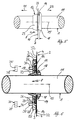
- a line in the form of a wire harness 1 is passed through a wall 2 passed, which two corresponding and partial walls 3 and 4 to be fastened to one another (FIG. 1).
- wall 2 is the end wall of a motor vehicle, the first partial wall 3 being a component the passenger compartment and the second part 4 part of the Stem module can be.
- the first partial wall 3 has an edge 5, which are effective from a first partial opening 6 Recess is interrupted.
- the second partial wall 4 also has an edge 5 'on that of a second partial opening 6 'effective recess is interrupted.
- the recess edges 9.9 'of both partial openings 6.6' run arcuate and are with part walls attached to each other 3, 4 with their concave sides facing each other.
- the recess edge 9 of the first partial opening 6 spans an arc of more than 180 °, see above that the cross section of the first partial opening 6 in the direction of interrupted edge 5 is tapered.
- This geometric Design causes two approximately wedge-shaped Transitional areas 10 of the partial wall 3 with the edge 5 and the recess edge 9 as a wedge leg.
- transition areas 10 are as a locking or restraining device against an undesirable Falling out of the wire harness 1 takes effect when the wire harness 1 has been inserted into the partial opening 6.
- the partial opening 6 is dimensioned such that the recess edge 9 on the peripheral jacket 11 of the wiring harness 1 or on one the peripheral jacket 11 surrounding and yet to be explained sealing element in the form of a sealing spout 12 is approximately flush.
- the light forming the interruption of the edge 5 Opening width w between the two transition areas 10 therefore smaller than the diameter of the wire harness 1 or as the diameter of the area enclosed by the recess edge 9 the spout 12.
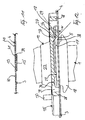
- the partial wall 3 shows the state of attachment of the two partial walls 3, 4.
- the two part walls 3 and 4 overlap their recess edges 9.9 'and with edge segments 13.13' and lie with each other with these edge segments 13, 13 'plane-parallel on (Fig.3, Fig.4).
- the partial wall 3 are edge segments 13 assigned, which the recess edge 9 and the transition areas 10 run approximately in the direction of the edge 5 adjacent.
- the edge segments 13 'assigned to the partial wall 4 are the same Recessing edge 9 'adjacent and run approximately in the direction the edge 5 '.
- Are in the area of mutual overlap the partial walls 3, 4 are fastened to one another, e.g. by welding, especially spot welding. This is for example in 3 indicated by means of the welding points 14.
- the recessed edges are in the fastening state of the two partial walls 3, 4 9.9 'approximately concentric to the central longitudinal axis 15 the rotationally symmetrical spout 12 is arranged.
- the central longitudinal axis 15 runs approximately across or at right angles to Wall plane of the wall 2.
- the partial opening 6 ' has a larger radius than the partial opening 6, so that the two of the edge 5 ' adjacent edge portions 16 of the recess edge 9 ' Partial wall 3 overlap and the recess edge 9 transversely to the central longitudinal axis 15 of the wiring harness 1 surrounded with a radial distance (Fig.4).
- the at least partially, but preferably completely elastic Grommet 12 includes the peripheral jacket 11 of the wiring harness 1 tight (Fig. 3).
- the spout 12 can be made in one piece (e.g. cohesively) be connected to the peripheral jacket 11 or as a separate Component applied to the wiring harness 1.
- the spout 12 carries two spaced apart in the direction 8 and concentric with each other with respect to the central longitudinal axis 15 arranged lips.
- the lip which acts as a sealing lip 17 a larger diameter than the second lip, which acts as the retaining lip 18 is designated.
- the one in the direction of the central longitudinal axis 15 running thickness cross section of the two lips is also different, the retaining lip 18 the larger Has thickness cross-section.
- the holding lip 18 is dimensioned such that it opens the partial opening 6 of the first sub-wall 3 after inserting the wiring harness 1 covers. Because of their relatively large thickness cross-section the retaining lip has along the central longitudinal axis 15 18 a certain inherent rigidity despite elastic properties on which is an all too easy bending of the radial outer segments of the retaining lip 18 prevented. The lip 18 is therefore an axial securing against pulling out or pushing the cable harness 1 out of the first partial wall 3 effective in the direction of displacement 21.
- opposite direction 22 is a removal of the wiring harness 1 from its target assembly position especially prevented by a spout 23 whose thickness cross section runs along the central longitudinal axis 15 is relatively large - in the present embodiment more than twice the size of the corresponding one Cross section of the retaining lip 18 - and therefore also against one All too easy bending or compression is protected.
- This spout 23 is concentric with the central longitudinal axis 15 arranged and integrally connected to the sealing lip 17.
- the nozzle extension 23 borders directly on that of the retaining lip 18 facing away from the lip surface 24 of the sealing lip 17.
- the Spout approach 23 has a frustoconical cross section, the largest truncated cone diameter facing the lip surface 24 is. This largest truncated cone diameter is smaller than the diameter of the retaining lip 18.
- the cross section of the spout 23 tapers from the surface of the lips 24 in the direction of implementation 8 or in the direction of displacement 21.
- the sealing lip 17 has the actual one Sealing function. It has a larger radius as the holding lip 18 and is in the assembled state over the opening edge the feed-through opening 7, that of both Cut-out edges 9, 9 'and one of the second partial wall 4 not covered portion of the edge 5 of the first partial wall 3 is formed.
- the cross-sectional thickness of the sealing lip 17 is in comparison to the cross-sectional thickness of the retaining lip 18 small. This small cross-section of thickness makes it possible among other things, that the sealing lip 17 between the wall 2 and a separate clamping body 25 (Fig.7) with little effort can be immovably clamped and thereby the lead-through opening 7 absolutely sealed when assembled is.
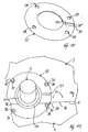
- the clamping body 25 has in the illustrated embodiment the shape of an annular disc with a central sealing opening 26.
- This sealing opening 26 is circular and surrounds the spout 23.
- the sealing opening 26 is radial from surround a sealing edge 34 which has a radially inner Clamping web 27 and a radially outer contact web 28 comprises.
- the Inner diameter of the contact web 28 is slightly larger than that Outer diameter of the sealing lip 17 and is therefore fixed in the clamp Sealing lip 17 directly on the wall 2.
- the jetty 28 stands in the axial direction or in the direction of the central longitudinal axis 15 beyond the clamping web 27.
- This axial protrusion d enables axial and radial coverage at the same time the sealing lip 17. This in turn enables without additional Components provide good protection against damage for the sealing lip 17 and thus an effective seal of the through opening 7.
- the landing stage 28 is interposed with an additional one Layer (e.g. insulating or sealing layer) on the wall 2. This can further increase the sealing effect be improved.
- Layer e.g. insulating or sealing layer
- the clamping body 25 is designed such that the clamping web 27 in the assembled state on the lip surface 24 of the sealing lip 17 rests and it runs in the direction of implementation 8 Clamping force clamped (Fig. 6). To generate the clamping force clamping devices to be explained are provided. These clamping devices can the clamping body 25 in the direction 8 apply force so that the sealing edge 34, in particular the dock 28, pressed against the wall 2 and, if necessary the clamping means is compressed and the clamping web 27 on creates the lip surface 24. In a preferred embodiment the projection d is smaller than the axial cross-sectional thickness the sealing lip 17. This will seal the feed-through opening 7 reinforced with little effort.
- the contact web 28 is of a total of four in the axial direction or in the clamping force direction extending receiving channels 29 for receiving each penetrates a threaded bolt 30 which on the Partial wall 3 or 4 attached, e.g. is welded on (Fig. 9).
- a threaded bolt 30 which on the Partial wall 3 or 4 attached, e.g. is welded on (Fig. 9).
- Each two threaded bolts 30 are on a partial wall 3 or partial wall 4 attached, the central longitudinal axes of the threaded bolts 30 run at right angles to the wall plane of wall 2.
- the threaded bolts 30 have an external thread, not shown here and each correspond to an internal thread 35, which is part of a clamping element 36 (e.g. a Screw nut).
- the clamping element 36 is used during assembly of the clamping body 25 on the wall 2 facing away and over the Receiving channel 29 protruding free end of the threaded bolt 30 screwed on. By screwing on the clamping element 36 is the sealing lip 17 axially facing away from the surface annular sealing edge 34 of the clamp body 25 automatically loaded with a clamping force.
- the sealing edge 34 of the clamp body 25 is transverse to one its circumferential direction, i.e. radially extending slot 31 severed. This allows the clamp body 25 to be particularly easy to install to be applied to the wiring harness 1 as Clamping jaw for fixing the sealing lip 17 effectively his.
- the threaded bolts 30 and the receiving channels 29 can be arranged such that the slot 31 is not positioned at right angles to the parting line 32 between the two part walls 3, 4 during assembly .
- the slot 31 is positioned parallel to the parting line 32.
- the boundary section 33 then lies only against the partial wall 3, while the boundary section 33 ′ only abuts against the partial wall 4.
- the threaded bolts 30 are arranged so as to be distributed in the circumferential direction of the sealing lip 17 in such a way that the angular arc measure differs between adjacent threaded bolts. This Coding "ensures a clear functional position of the clamping body 25.
- the receiving channels 29 or the threaded bolts 30 are not arranged point-symmetrically to the center of the sealing opening 26. In a preferred embodiment, the receiving channels 29 or the threaded bolts 30 are mirror-symmetrical to the cutting line VIII-VIII arranged in Fig.7.
- the wiring harness 1 When assembling, the wiring harness 1 is first in the direction of insertion 20, i.e. transversely to the direction 8, in the partial opening 6 of the first partial wall 3 is used.
- the ring-shaped clamp body 25 can - but does not have to - at this point be applied to the wiring harness 1.
- the two Partial walls 3, 4 from the starting position approximately in the direction of implementation 8 approximated each other.
- the radius of the partial opening 6 'of the second partial wall 4 is larger is than the radius of the retaining lip 18, manufacturing and Due to the installation, there are dimensional tolerances between the components to be installed Components taken into account and the second partial wall 4 can in the implementation direction 8 to the first partial wall 3 without obstruction be introduced.
- This is for example with a automated manufacturing and especially in the modular construction of vehicles of great importance since here the Vehicle modules must be partially merged horizontally.
- the partial walls 3, 4 brought together overlap themselves with their edge segments 13, 13 'and are in the range of Edge segments 13, 13 'by means of a suitable connecting technique (e.g. spot welding) firmly connected.
- the clamping body 25 is first unscrewed. Are the partitions 3,4 releasably attached to each other (e.g. screwed together), then the partial walls 3, 4 separated from each other and then the wiring harness 1 becomes the insertion direction 20 pulled out of the partial opening 6 in the opposite direction.
- the wiring harness 1 preferably in the direction of displacement 21 through the Feed-through opening 7 moves and the holding lip 18 is made the feed-through opening 7 is knotted out.
- FIG. 10 shows the clamping body 25 in a further embodiment shown, the receiving channels 29 between the inner Clamping web 27 and an outer contact web 28 'arranged are.
- This outer contact web 28 ' is made considerably narrower as the corresponding landing stage 28 according to FIG. 7.
- the Contact web 28 ' is on the radially outer edge of the clamping body 25 limited.
- the clamping body 25 according to FIG. 10 is preferably made of metal, especially as a stamped or stamped part, manufactured.
- the receiving channels 29 are preferably the outer Contact web 28 'is closer in the radial direction than the inner one Clamping web 27. This will result in excessive crushing of the avoiding sealing lip 17 to be clamped during the assembly process.
- the partial wall 4 is cranked, i.e. she points between its edge segment 13 'and the rest of the area an offset 39. This will make the otherwise between both partial walls 3, 4 resulting surface jump 38 compensated.
- the two surfaces facing away from the edge segment 13 ' of the partial walls 3, 4 form the same surface level 40
- Area 41 formed in the bend 39 is preferred in the assembly of the sealing element, in particular of an elastic sealing lip 17 filled.
- the overlapping partial walls 3, 4 in the area of the edge segments 13, 13 ', heel-like Surface jump 38 compensated in that the sealing lip 17 facing side of the clamp body 25 a bevel 37, which is located directly on the sealing lip 17th creates.
- the compensation slope 37 preferably runs in one Angle w of about 45 ° compared to the immediately neighboring one Surface areas of the clamp body 25 or its sealing edge 34.
- the bevel 37 is on the clamping web 27, namely at the radially inner region thereof.
- the exact arrangement and the cross section of the bevel 37 on Clamping body 25 depends individually on the course of the surface crack 38 on the partial walls 3, 4 and the intended relative position of the clamping body 25 relative to the partial walls 3, 4.
- Fig. 13 runs the compensation slope 37 corresponding to the straight line Edge edges 5 of the partial wall 3 linearly in the manner of approximately one Chord along the clamp body 25.
Applications Claiming Priority (2)
| Application Number | Priority Date | Filing Date | Title |
|---|---|---|---|
| DE1998157784 DE19857784A1 (de) | 1998-12-15 | 1998-12-15 | Leitungsdurchführung durch eine Wand |
| DE19857784 | 1998-12-15 |
Publications (3)
| Publication Number | Publication Date |
|---|---|
| EP1010584A2 true EP1010584A2 (fr) | 2000-06-21 |
| EP1010584A3 EP1010584A3 (fr) | 2003-09-24 |
| EP1010584B1 EP1010584B1 (fr) | 2006-04-05 |
Family
ID=7891122
Family Applications (1)
| Application Number | Title | Priority Date | Filing Date |
|---|---|---|---|
| EP19990123552 Expired - Lifetime EP1010584B1 (fr) | 1998-12-15 | 1999-11-26 | Traversée de conduite à travers une paroi |
Country Status (3)
| Country | Link |
|---|---|
| EP (1) | EP1010584B1 (fr) |
| JP (1) | JP2000201420A (fr) |
| DE (2) | DE19857784A1 (fr) |
Cited By (7)
| Publication number | Priority date | Publication date | Assignee | Title |
|---|---|---|---|---|
| DE10341211A1 (de) * | 2003-09-04 | 2005-04-14 | Opel Eisenach Gmbh | Querträger für ein Kraftfahrzeug |
| WO2006131298A1 (fr) * | 2005-06-04 | 2006-12-14 | Leoni Bordnetz-Systeme Gmbh | Element d'etancheite pour realiser l'etancheite d'un corps en forme d'extrude, dans une ouverture d'une paroi |
| FR2903533A1 (fr) * | 2006-07-06 | 2008-01-11 | Renault Sas | Bague support de cablage electrique montee sur le tablier d'un vehicule automobile |
| EP2412555A1 (fr) * | 2009-03-25 | 2012-02-01 | Mitsubishi Heavy Industries, Ltd. | Chariot élévateur à fourche |
| NL1040145C2 (nl) * | 2013-04-03 | 2014-10-06 | Krn Montage B V | Kolomring ten behoeve van zwevende plafonds en wijze van montage. |
| EP2886744A1 (fr) * | 2013-12-17 | 2015-06-24 | Geberit International AG | Semelle de coffrage |
| US20210249161A1 (en) * | 2020-02-06 | 2021-08-12 | Abb Schweiz Ag | Bushing for a medium voltage switchgear |
Families Citing this family (3)
| Publication number | Priority date | Publication date | Assignee | Title |
|---|---|---|---|---|
| DE10312920B4 (de) * | 2003-03-22 | 2005-08-04 | Sma Technologie Ag | Vorrichtung zur Fixierung eines Rundsteckers in der Steckerbuchse |
| DE202008007624U1 (de) | 2008-06-06 | 2008-08-28 | Woco Industrietechnik Gmbh | Dichtungskörper |
| JP7094736B2 (ja) * | 2018-03-16 | 2022-07-04 | ダイハツ工業株式会社 | ワイヤハーネスカバー構造 |
Citations (2)
| Publication number | Priority date | Publication date | Assignee | Title |
|---|---|---|---|---|
| DE3431617A1 (de) | 1984-08-28 | 1986-03-06 | Fa. Lisa Dräxlmaier, 8313 Vilsbiburg | Feuchtigkeitsdichte leitungsfuehrung |
| DE3701597A1 (de) | 1987-01-21 | 1988-08-04 | Opel Adam Ag | Kraftfahrzeug |
Family Cites Families (9)
| Publication number | Priority date | Publication date | Assignee | Title |
|---|---|---|---|---|
| US3123662A (en) * | 1964-03-03 | Strain relief collet | ||
| US3518359A (en) * | 1968-03-28 | 1970-06-30 | Amp Inc | Heat-shrinkable sealing and strain-relief fittings for electrical cables |
| US3548079A (en) * | 1969-05-16 | 1970-12-15 | Raychem Corp | Bulkhead feedthrough |
| US4656689A (en) * | 1986-04-01 | 1987-04-14 | Molded Products Company | Grommet |
| US4797513A (en) * | 1987-11-25 | 1989-01-10 | Yazaki Corporation | Grommet with wires sealed thereto and method of forming same |
| US4860791A (en) * | 1988-12-05 | 1989-08-29 | Speed Queen Company | Strain relief clamp for washing machine drain hose |
| DE9404575U1 (de) * | 1994-03-18 | 1994-05-19 | Cornelius Berthold | Dichtmanschette für Hauseinführungen |
| DE19526927A1 (de) * | 1995-07-24 | 1997-01-30 | Porsche Ag | Dichtungstülle mit Sicherungsteil |
| FR2747449B1 (fr) * | 1996-04-11 | 1998-06-05 | Peugeot | Joint d'etancheite pour une traversee de paroi, procede de realisation d'un tel joint, et assemblage obtenu avec ce joint ou par ce procede |
-
1998
- 1998-12-15 DE DE1998157784 patent/DE19857784A1/de not_active Withdrawn
-
1999
- 1999-11-26 EP EP19990123552 patent/EP1010584B1/fr not_active Expired - Lifetime
- 1999-11-26 DE DE59913301T patent/DE59913301D1/de not_active Expired - Fee Related
- 1999-12-14 JP JP11376564A patent/JP2000201420A/ja active Pending
Patent Citations (2)
| Publication number | Priority date | Publication date | Assignee | Title |
|---|---|---|---|---|
| DE3431617A1 (de) | 1984-08-28 | 1986-03-06 | Fa. Lisa Dräxlmaier, 8313 Vilsbiburg | Feuchtigkeitsdichte leitungsfuehrung |
| DE3701597A1 (de) | 1987-01-21 | 1988-08-04 | Opel Adam Ag | Kraftfahrzeug |
Cited By (11)
| Publication number | Priority date | Publication date | Assignee | Title |
|---|---|---|---|---|
| DE10341211A1 (de) * | 2003-09-04 | 2005-04-14 | Opel Eisenach Gmbh | Querträger für ein Kraftfahrzeug |
| DE10341211B4 (de) * | 2003-09-04 | 2006-05-24 | GM Global Technology Operations, Inc., Detroit | Kabeldurchführung durch eine Stirnwand eines Kraftfahrzeugs |
| WO2006131298A1 (fr) * | 2005-06-04 | 2006-12-14 | Leoni Bordnetz-Systeme Gmbh | Element d'etancheite pour realiser l'etancheite d'un corps en forme d'extrude, dans une ouverture d'une paroi |
| US7709755B2 (en) | 2005-06-04 | 2010-05-04 | Leoni Bordnetz-Systeme Gmbh | Sealing element for sealing a strand-shaped body in an aperture of a wall |
| FR2903533A1 (fr) * | 2006-07-06 | 2008-01-11 | Renault Sas | Bague support de cablage electrique montee sur le tablier d'un vehicule automobile |
| EP2412555A1 (fr) * | 2009-03-25 | 2012-02-01 | Mitsubishi Heavy Industries, Ltd. | Chariot élévateur à fourche |
| EP2412555A4 (fr) * | 2009-03-25 | 2013-12-18 | Mitsubishi Nichiyu Forklift Co | Chariot élévateur à fourche |
| NL1040145C2 (nl) * | 2013-04-03 | 2014-10-06 | Krn Montage B V | Kolomring ten behoeve van zwevende plafonds en wijze van montage. |
| EP2886744A1 (fr) * | 2013-12-17 | 2015-06-24 | Geberit International AG | Semelle de coffrage |
| US20210249161A1 (en) * | 2020-02-06 | 2021-08-12 | Abb Schweiz Ag | Bushing for a medium voltage switchgear |
| US11742114B2 (en) * | 2020-02-06 | 2023-08-29 | Abb Schweiz Ag | Bushing for a medium voltage switchgear |
Also Published As
| Publication number | Publication date |
|---|---|
| DE59913301D1 (de) | 2006-05-18 |
| DE19857784A1 (de) | 2000-06-29 |
| EP1010584A3 (fr) | 2003-09-24 |
| EP1010584B1 (fr) | 2006-04-05 |
| JP2000201420A (ja) | 2000-07-18 |
Similar Documents
| Publication | Publication Date | Title |
|---|---|---|
| EP0401659B1 (fr) | Fixation d'une bavette de garde-boue | |
| DE102006056065B4 (de) | Vormontierte Kontaktiereinheit und Befestigungsanordnung | |
| EP3625860A1 (fr) | Passage de câble | |
| EP3821478A1 (fr) | Boîtier de batterie | |
| DE10302707A1 (de) | Anordnung zur abstandsvariabien Verbindung eines Montageteils mit einer Unterkonstruktion | |
| EP3789280A1 (fr) | Élément de console, système pourvu d'élément de console et procédé de liaison d'un élément de console à un plancher d'un véhicule | |
| EP1010584B1 (fr) | Traversée de conduite à travers une paroi | |
| DE102006022382A1 (de) | Vorrichtung und Verfahren zur Befestigung eines Wischermotors an ein Wischergestänge | |
| DE19821160C1 (de) | Befestigungssystem | |
| EP1612432B1 (fr) | Dispositif de fixation pour habillage et méthode de fixation | |
| EP1583683A1 (fr) | Ensemble pour raccorder une premiere piece tubulaire une deuxieme piece | |
| DE202008001661U1 (de) | Brücke oder Brückenabschnitt | |
| EP3126575B1 (fr) | Corniche de pont et ensemble de fixation d'une corniche de pont | |
| DE102012013884A1 (de) | Befestigungsanordnung einer Abgas führenden Anbaueinrichtung | |
| DE10035795B4 (de) | Klemmschuhanordnung | |
| WO2011054330A1 (fr) | Cylindre hydraulique | |
| WO2004022416A1 (fr) | Composant hybride a elements de fixation en plastique moules par injection pour vehicules automobiles et procede de reparation dudit composant | |
| EP3869047B1 (fr) | Élément d'appui comportant un manchon d'appui et un moyen de palier, moyen de palier destiné à la formation d'un tel élément d'appui, agencement comportant un tel élément d'appui et un corps creux ainsi que procédé de formation d'un tel agencement | |
| EP3631901A1 (fr) | Dispositif de mise à la terre pour véhicules | |
| DE10236550B4 (de) | Haltevorrichtung für ein Leitungsstrang-Schuhelement | |
| DE102006003448B3 (de) | Befestigungsanordnung zur Anbringung einer Leitung an einem Kraftfahrzeug | |
| DE10219829B4 (de) | Vorrichtung zum Befestigen eines Abgaskrümmers | |
| DE2232990A1 (de) | Verfahren und verbindungsplatte zum verbinden eines oelkuehlers mit einem motorblock | |
| DE102014012873A1 (de) | Verbindungselement zum elektrischen Verbinden von Flachleitern | |
| DE19859803A1 (de) | Polklemme zur Befestigung wenigstens eines Kabels an einem Pol eines Akkumulators |
Legal Events
| Date | Code | Title | Description |
|---|---|---|---|
| PUAI | Public reference made under article 153(3) epc to a published international application that has entered the european phase |
Free format text: ORIGINAL CODE: 0009012 |
|
| AK | Designated contracting states |
Kind code of ref document: A2 Designated state(s): AT BE CH CY DE DK ES FI FR GB GR IE IT LI LU MC NL PT SE |
|
| AX | Request for extension of the european patent |
Free format text: AL;LT;LV;MK;RO;SI |
|
| PUAL | Search report despatched |
Free format text: ORIGINAL CODE: 0009013 |
|
| AK | Designated contracting states |
Kind code of ref document: A3 Designated state(s): AT BE CH CY DE DK ES FI FR GB GR IE IT LI LU MC NL PT SE |
|
| AX | Request for extension of the european patent |
Extension state: AL LT LV MK RO SI |
|
| 17P | Request for examination filed |
Effective date: 20030819 |
|
| AKX | Designation fees paid |
Designated state(s): DE FR GB IT |
|
| 17Q | First examination report despatched |
Effective date: 20040707 |
|
| GRAP | Despatch of communication of intention to grant a patent |
Free format text: ORIGINAL CODE: EPIDOSNIGR1 |
|
| GRAS | Grant fee paid |
Free format text: ORIGINAL CODE: EPIDOSNIGR3 |
|
| GRAA | (expected) grant |
Free format text: ORIGINAL CODE: 0009210 |
|
| AK | Designated contracting states |
Kind code of ref document: B1 Designated state(s): DE FR GB IT |
|
| PG25 | Lapsed in a contracting state [announced via postgrant information from national office to epo] |
Ref country code: IT Free format text: LAPSE BECAUSE OF FAILURE TO SUBMIT A TRANSLATION OF THE DESCRIPTION OR TO PAY THE FEE WITHIN THE PRESCRIBED TIME-LIMIT;WARNING: LAPSES OF ITALIAN PATENTS WITH EFFECTIVE DATE BEFORE 2007 MAY HAVE OCCURRED AT ANY TIME BEFORE 2007. THE CORRECT EFFECTIVE DATE MAY BE DIFFERENT FROM THE ONE RECORDED. Effective date: 20060405 Ref country code: GB Free format text: LAPSE BECAUSE OF FAILURE TO SUBMIT A TRANSLATION OF THE DESCRIPTION OR TO PAY THE FEE WITHIN THE PRESCRIBED TIME-LIMIT Effective date: 20060405 |
|
| REG | Reference to a national code |
Ref country code: GB Ref legal event code: FG4D Free format text: NOT ENGLISH |
|
| REF | Corresponds to: |
Ref document number: 59913301 Country of ref document: DE Date of ref document: 20060518 Kind code of ref document: P |
|
| GBV | Gb: ep patent (uk) treated as always having been void in accordance with gb section 77(7)/1977 [no translation filed] |
Effective date: 20060405 |
|
| PLBE | No opposition filed within time limit |
Free format text: ORIGINAL CODE: 0009261 |
|
| STAA | Information on the status of an ep patent application or granted ep patent |
Free format text: STATUS: NO OPPOSITION FILED WITHIN TIME LIMIT |
|
| EN | Fr: translation not filed | ||
| 26N | No opposition filed |
Effective date: 20070108 |
|
| PG25 | Lapsed in a contracting state [announced via postgrant information from national office to epo] |
Ref country code: FR Free format text: LAPSE BECAUSE OF FAILURE TO SUBMIT A TRANSLATION OF THE DESCRIPTION OR TO PAY THE FEE WITHIN THE PRESCRIBED TIME-LIMIT Effective date: 20070309 |
|
| PG25 | Lapsed in a contracting state [announced via postgrant information from national office to epo] |
Ref country code: FR Free format text: LAPSE BECAUSE OF FAILURE TO SUBMIT A TRANSLATION OF THE DESCRIPTION OR TO PAY THE FEE WITHIN THE PRESCRIBED TIME-LIMIT Effective date: 20060405 |
|
| PGFP | Annual fee paid to national office [announced via postgrant information from national office to epo] |
Ref country code: DE Payment date: 20081121 Year of fee payment: 10 |
|
| PG25 | Lapsed in a contracting state [announced via postgrant information from national office to epo] |
Ref country code: DE Free format text: LAPSE BECAUSE OF NON-PAYMENT OF DUE FEES Effective date: 20100601 |