EP1010584A2 - Conduit passage through a wall - Google Patents
Conduit passage through a wall Download PDFInfo
- Publication number
- EP1010584A2 EP1010584A2 EP99123552A EP99123552A EP1010584A2 EP 1010584 A2 EP1010584 A2 EP 1010584A2 EP 99123552 A EP99123552 A EP 99123552A EP 99123552 A EP99123552 A EP 99123552A EP 1010584 A2 EP1010584 A2 EP 1010584A2
- Authority
- EP
- European Patent Office
- Prior art keywords
- edge
- sealing
- partial
- opening
- wall
- Prior art date
- Legal status (The legal status is an assumption and is not a legal conclusion. Google has not performed a legal analysis and makes no representation as to the accuracy of the status listed.)
- Granted
Links
- 238000007789 sealing Methods 0.000 claims description 120
- 230000002093 peripheral effect Effects 0.000 claims description 8
- 238000005192 partition Methods 0.000 description 9
- 238000004519 manufacturing process Methods 0.000 description 7
- 238000003466 welding Methods 0.000 description 7
- 238000010276 construction Methods 0.000 description 6
- 230000000694 effects Effects 0.000 description 6
- 239000002184 metal Substances 0.000 description 5
- 230000008901 benefit Effects 0.000 description 4
- 238000013461 design Methods 0.000 description 3
- 238000006073 displacement reaction Methods 0.000 description 3
- 238000003780 insertion Methods 0.000 description 3
- 230000037431 insertion Effects 0.000 description 3
- 230000007704 transition Effects 0.000 description 3
- 238000004026 adhesive bonding Methods 0.000 description 2
- 238000005452 bending Methods 0.000 description 2
- 238000009434 installation Methods 0.000 description 2
- 239000000463 material Substances 0.000 description 2
- 238000000034 method Methods 0.000 description 2
- 230000000149 penetrating effect Effects 0.000 description 2
- 229910000639 Spring steel Inorganic materials 0.000 description 1
- 229910000831 Steel Inorganic materials 0.000 description 1
- 238000013459 approach Methods 0.000 description 1
- 230000006835 compression Effects 0.000 description 1
- 238000007906 compression Methods 0.000 description 1
- 239000004020 conductor Substances 0.000 description 1
- 238000005520 cutting process Methods 0.000 description 1
- 238000005516 engineering process Methods 0.000 description 1
- 230000007613 environmental effect Effects 0.000 description 1
- 238000012423 maintenance Methods 0.000 description 1
- 230000003287 optical effect Effects 0.000 description 1
- 230000002028 premature Effects 0.000 description 1
- 238000003825 pressing Methods 0.000 description 1
- 230000008569 process Effects 0.000 description 1
- 230000008439 repair process Effects 0.000 description 1
- 230000000452 restraining effect Effects 0.000 description 1
- 238000005476 soldering Methods 0.000 description 1
- 238000003892 spreading Methods 0.000 description 1
- 230000007480 spreading Effects 0.000 description 1
- 239000010959 steel Substances 0.000 description 1
- 238000003860 storage Methods 0.000 description 1
- 238000004073 vulcanization Methods 0.000 description 1
- 239000002699 waste material Substances 0.000 description 1
Images


Classifications
-
- H—ELECTRICITY
- H02—GENERATION; CONVERSION OR DISTRIBUTION OF ELECTRIC POWER
- H02G—INSTALLATION OF ELECTRIC CABLES OR LINES, OR OF COMBINED OPTICAL AND ELECTRIC CABLES OR LINES
- H02G3/00—Installations of electric cables or lines or protective tubing therefor in or on buildings, equivalent structures or vehicles
- H02G3/22—Installations of cables or lines through walls, floors or ceilings, e.g. into buildings
-
- B—PERFORMING OPERATIONS; TRANSPORTING
- B60—VEHICLES IN GENERAL
- B60R—VEHICLES, VEHICLE FITTINGS, OR VEHICLE PARTS, NOT OTHERWISE PROVIDED FOR
- B60R16/00—Electric or fluid circuits specially adapted for vehicles and not otherwise provided for; Arrangement of elements of electric or fluid circuits specially adapted for vehicles and not otherwise provided for
- B60R16/02—Electric or fluid circuits specially adapted for vehicles and not otherwise provided for; Arrangement of elements of electric or fluid circuits specially adapted for vehicles and not otherwise provided for electric constitutive elements
- B60R16/0207—Wire harnesses
- B60R16/0215—Protecting, fastening and routing means therefor
- B60R16/0222—Grommets
Definitions
- the invention relates to a bushing for a line a wall.
- the wall is arranged, for example, in a motor vehicle and here in particular is designed as a wall between the engine compartment and the passenger compartment of a vehicle.
- Cable bundles with electrical conductors for motor vehicles as are known from DE 34 31 617 A1 and from DE 37 40 582 A1, are usually passed through a through opening penetrating the wall, in that the cable bundle and a sealing sleeve surrounding the cable bundle pass through the cable bundle in the longitudinal direction opening through ".
- threading work is laborious and expensive in terms of assembly.
- it is disadvantageous for threading that the lead-through opening must be made particularly large if one or more associated plugs are threaded through the wall in the case of electrical lines.
- the seal of the lead-through opening is particularly complex and is therefore susceptible to premature failure of the desired sealing function, which increases maintenance and repair work and the associated costs.
- the invention has for its object a technical assembly easy implementation for a line through a wall too create.
- the bushing has a wall which comprises several part walls. These partial walls are then firmly connected to one another during assembly - depending on the application, detachable or non-detachable.
- the line is first inserted transversely to the longitudinal direction of the line into the partial opening of a first partial wall which is open at the edge.
- at least one second partial wall which also contains a partial opening that is open at the edge, is attached to the first partial wall.
- the partial opening of this second partial wall, which is open at the edge corresponds to the partial opening of the first partial wall, which is open at the edge, so that the partial openings together into an edge-closed through opening for the line being transformed.
- any threading work is advantageous when installing the line avoided. Since the line is transverse to the longitudinal direction of the line is inserted into a first partial opening and further partial openings additional partitions after the first part can be applied, the edges of the partial openings Flank the circumference of the line particularly tightly.
- the lead-through opening the wall is therefore in contrast to conventional ones Constructions kept particularly small. Hence, column between line and lead-through opening with little effort and simple seal construction can be sealed. This Advantage in turn reduces manufacturing costs and improves the functional reliability of a seal used.
- Suitable sealing elements are located in the area of the lead-through opening (e.g. grommets, sealing rings, washers) used, which e.g. immediately during the production of the line and / or subsequently as separate components on the circumference of the line can be fixed.
- the area of the lead-through opening can also be foamed, Vulcanization or the like. The line are sealed.
- the corresponding ones Partial openings formed differently the partial opening the first part wall preferably the largest proportion of the opening cross section of the through opening, around the To facilitate assembly of the line in the first partial wall.
- the feed-through opening preferably settles - as already above explained - from two partial openings together, because in this Case only two partitions are needed to carry out the line to realize. This is the way of manufacturing and the installation of the cable bushing is particularly easy to implement.
- Line represents a whole series of elongated - preferably hose-like, tube-like or cylindrical - components. It can be optical, electrical, hydraulic, pneumatic lines or the like. Both a single line and a bundle of lines (eg cable harness) can be passed through the through opening.
- the two partitions to each other, depending on Use case different fasteners provided his.
- As an inseparable attachment of the part walls to each other e.g. Suitable for gluing, welding, soldering, riveting.
- As releasable Fastening is, for example, screwing the part walls together suitable with each other.
- the partitions are depending on the application preferably made of metal or plastic. You can the partial walls made of plate-like panels or sheet metal cut according to the desired cross-sectional shape become. In a further preferred embodiment, the partial walls can by means of hinges or suitable connecting components releasably or permanently connected to each other his.
- the measure according to claim 2 enables a good adjustment of the Feed-through opening on the often circular or oval Cross-section of the line or a sealing grommet surrounding the line.
- a recess edge of a recess or a partial opening the line is approximately flush or relatively surrounded by a small radial distance. This means any Sealing problems further reduced.
- the line without any special assembly effort from the recess edge of the partial opening a first partial wall can be pre-fixed after the Line has been inserted into this partial opening. It can the outline of an opening edge section is a little smaller Image of the too extensive cross-section of the line or be the spout for a reliable pre-fixation of the line to support.
- the spout is preferably elastic educated.
- Claims 3 and 4 improve the fixation of the line during the assembly of the part walls.
- the one inserted in a partial opening The line is directed towards the edge of the Partial wall tapering recess edge from falling out the partial opening prevented. To a certain extent, the line is locked in the partial wall.
- the cable jacket or one surrounding the cable jacket Sealing element e.g. sealing spout
- an inherent elasticity has, whereby the conduit into the tapered Edge cutout is used without being damaged.
- adjacent part walls are in the assembled Condition of the wall overlaps and promote by this relative position the inherent stability of the wall.
- the one so formed labyrinthine parting line between the two sides the wall improved compared to a simple frontal system the edge of adjacent part walls also the tightness the Wall.
- the recess edge of the first partial wall is from Recessing edge of at least one other partial wall transverse to Execution direction - it corresponds approximately to the longitudinal direction of the line in the area of the wall - surrounded at a distance to allow assembly tolerances and dimensional tolerances of components of the implementation to be able to take into account.
- This allows the second part of the wall and, if necessary, other partial walls to the first partial wall without hindrance introduced (directionally in particular approximately parallel and / or perpendicular to the wall plane) and attached to it, even if the circumferential jacket of the pipe from a sealing grommet and / or other sealing elements is surrounded. This advantage supports automated production of the Execution.
- the invention further includes a structurally simple design Seal.
- Claim 7, which is inventive for itself strikes a sealing element interacting with a clamping body in front of a through opening in a wall Sealing through a pipe.
- the seal can either solely by means of the clamping body and the sealing element or in combination with other sealing parts.
- the seal is preferably supported by the Sealing element (e.g. designed as a spout) the peripheral jacket tightly surrounds the line.
- the sealing element preferably elastic and lies for sealing e.g. in the manner of a press fit on the peripheral jacket or with connected to the peripheral jacket in one piece.
- the sealing by means of a sealing element and sprag according to Claim 7 does not necessarily have to - as already said used in a wall and through opening according to claim 1 become. Rather, the aforementioned sealing construction both for one-piece walls with a closed edge or open edge through opening as well for the multi-part wall according to claim 1 suitable.
- the sealing lip of the sealing element and the Clamping body circular in cross section, whereby along the opening edge of a through opening on constructive easily achieved a uniform seal becomes.
- Other cross sections such as oval, triangular, rectangular or generally polygonal, but can also used and depending on the cross section of the through opening and / or the line can be selected.
- the wall and the clamping body correspond like a jaw with each other and thereby cause a particularly stable storage of the sealing element and its sealing lip on the wall.
- the clamping force is preferably by means of suitable clamping means achieved.
- the clamping force exerted on the sealing lip increases the Sealing effect of the sealing element in addition.
- the claims 8 to 11 support a mechanically stable Clamping of the sealing element. It is an effective one Clamping the sealing element with simple construction and inexpensive clamping devices.
- the preferred here The threaded bolts used can be arranged accordingly on the wall or part of the walls in a double function can be used as an external thread and also as a welding stud.
- the measure according to claim 12 improves the sealing of the Overlapping area of the overlapping part walls inexpensively and technically inexpensive.
- the cross section of the bevel is suitably adapted to the surface crack, for effective clamping of the sealing element and sealing to achieve.
- the compensation slope preferably runs constructively simple in a single level.
- the compensation slope forms an angle of approximately 45 ° with the immediately adjacent surface area of the clamping body on.
- the clamp body is preferably metallic, e.g. from steel or spring steel sheet. An inexpensive flat material, in particular from sheet metal, is also suitable.
- the clamping body is made of the metal sheet in one piece as a stamped or stamped part manufactured.
- the one with a central sealing opening Clamping body in the aforementioned metallic embodiments has the advantage that increased requirements for an easy to assemble Threading one or more lines or cable harnesses in the sealing opening.
- the clamp body can also be inexpensive from a suitable Be made of plastic.
- the plastic can be elastic or substantially inelastic.
- the measures according to claims 13 and 14 allow an encapsulated Arrangement of the actual sealing Sealing lip inside the sprag.
- This is the sealing element effective against damage and environmental influences protected.
- a constant sealing effect over a long service life is guaranteed.
- that is too clamp-fixing sealing lip with regard to its cross-sectional thickness or thickness in the initial state is greater than that in the clamping direction running distance between an outer jetty and in contrast an inner clamping web of the clamping body.
- This Geometric conditions allow with little effort an additional clamping or pressing of the sealing lip against the wall with a correspondingly higher sealing effect.
- Several types of sprags are advantageous for assembly held, which essentially only with regard the distance between the outer landing stage and the inner clamping stage differentiate.
- the slotted clamping body according to claim 16 simplifies the Assemble the bushing by simply pulling the clamp through Spreading is placed on the line. This assembly step can also be done at the cable manufacturer.
- the slotted clamp body has improved flexibility and can specifically jump a level or surface compensate for the overlapping part walls, if the slot is parallel to an overlapped edge a partial wall runs and the two on both sides of the Slotted areas of the sealing edge only each rest on a partial wall (with the sealing lip in between).
- the line is by means of a Circumferential direction of the line and on the sealing element attached fixing groove particularly easy to install in a first partial wall can be used if the wall consists of several Partial walls, each with a partial opening.
- the fixing groove is preferably self-contained in the aforementioned circumferential direction, so that the greatest possible variability in assembly the management is given.
- the implementation of the line according to the invention can be applied to all partitions.
- a preferred one is vehicle construction (claim 19), where a series of wall or body openings for cable sets and other lines must be taken into account.
- This has an effect here with the line bushing according to the invention achieved simplification of assembly particularly time and cost-saving.
- Partitions exist in motor vehicles e.g. between engine compartment and passenger compartment - the so-called Bulkhead - or between the passenger compartment and the rear compartment, which of Lines are crossed.
- the line is initially approximately transverse to the direction of implementation into an edge edge of a first partial wall, effective recess used as partial opening. After that, at least one other partial wall with a partial opening brought up to the first partial wall and attached to it.
- the partial walls take such a relative position to each other a that the mutually corresponding partial openings together form the lead-through opening.
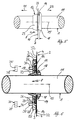
- a line in the form of a wire harness 1 is passed through a wall 2 passed, which two corresponding and partial walls 3 and 4 to be fastened to one another (FIG. 1).
- wall 2 is the end wall of a motor vehicle, the first partial wall 3 being a component the passenger compartment and the second part 4 part of the Stem module can be.
- the first partial wall 3 has an edge 5, which are effective from a first partial opening 6 Recess is interrupted.
- the second partial wall 4 also has an edge 5 'on that of a second partial opening 6 'effective recess is interrupted.
- the recess edges 9.9 'of both partial openings 6.6' run arcuate and are with part walls attached to each other 3, 4 with their concave sides facing each other.
- the recess edge 9 of the first partial opening 6 spans an arc of more than 180 °, see above that the cross section of the first partial opening 6 in the direction of interrupted edge 5 is tapered.
- This geometric Design causes two approximately wedge-shaped Transitional areas 10 of the partial wall 3 with the edge 5 and the recess edge 9 as a wedge leg.
- transition areas 10 are as a locking or restraining device against an undesirable Falling out of the wire harness 1 takes effect when the wire harness 1 has been inserted into the partial opening 6.
- the partial opening 6 is dimensioned such that the recess edge 9 on the peripheral jacket 11 of the wiring harness 1 or on one the peripheral jacket 11 surrounding and yet to be explained sealing element in the form of a sealing spout 12 is approximately flush.
- the light forming the interruption of the edge 5 Opening width w between the two transition areas 10 therefore smaller than the diameter of the wire harness 1 or as the diameter of the area enclosed by the recess edge 9 the spout 12.
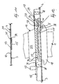
- the partial wall 3 shows the state of attachment of the two partial walls 3, 4.
- the two part walls 3 and 4 overlap their recess edges 9.9 'and with edge segments 13.13' and lie with each other with these edge segments 13, 13 'plane-parallel on (Fig.3, Fig.4).
- the partial wall 3 are edge segments 13 assigned, which the recess edge 9 and the transition areas 10 run approximately in the direction of the edge 5 adjacent.
- the edge segments 13 'assigned to the partial wall 4 are the same Recessing edge 9 'adjacent and run approximately in the direction the edge 5 '.
- Are in the area of mutual overlap the partial walls 3, 4 are fastened to one another, e.g. by welding, especially spot welding. This is for example in 3 indicated by means of the welding points 14.
- the recessed edges are in the fastening state of the two partial walls 3, 4 9.9 'approximately concentric to the central longitudinal axis 15 the rotationally symmetrical spout 12 is arranged.
- the central longitudinal axis 15 runs approximately across or at right angles to Wall plane of the wall 2.
- the partial opening 6 ' has a larger radius than the partial opening 6, so that the two of the edge 5 ' adjacent edge portions 16 of the recess edge 9 ' Partial wall 3 overlap and the recess edge 9 transversely to the central longitudinal axis 15 of the wiring harness 1 surrounded with a radial distance (Fig.4).
- the at least partially, but preferably completely elastic Grommet 12 includes the peripheral jacket 11 of the wiring harness 1 tight (Fig. 3).
- the spout 12 can be made in one piece (e.g. cohesively) be connected to the peripheral jacket 11 or as a separate Component applied to the wiring harness 1.
- the spout 12 carries two spaced apart in the direction 8 and concentric with each other with respect to the central longitudinal axis 15 arranged lips.
- the lip which acts as a sealing lip 17 a larger diameter than the second lip, which acts as the retaining lip 18 is designated.
- the one in the direction of the central longitudinal axis 15 running thickness cross section of the two lips is also different, the retaining lip 18 the larger Has thickness cross-section.
- the holding lip 18 is dimensioned such that it opens the partial opening 6 of the first sub-wall 3 after inserting the wiring harness 1 covers. Because of their relatively large thickness cross-section the retaining lip has along the central longitudinal axis 15 18 a certain inherent rigidity despite elastic properties on which is an all too easy bending of the radial outer segments of the retaining lip 18 prevented. The lip 18 is therefore an axial securing against pulling out or pushing the cable harness 1 out of the first partial wall 3 effective in the direction of displacement 21.
- opposite direction 22 is a removal of the wiring harness 1 from its target assembly position especially prevented by a spout 23 whose thickness cross section runs along the central longitudinal axis 15 is relatively large - in the present embodiment more than twice the size of the corresponding one Cross section of the retaining lip 18 - and therefore also against one All too easy bending or compression is protected.
- This spout 23 is concentric with the central longitudinal axis 15 arranged and integrally connected to the sealing lip 17.
- the nozzle extension 23 borders directly on that of the retaining lip 18 facing away from the lip surface 24 of the sealing lip 17.
- the Spout approach 23 has a frustoconical cross section, the largest truncated cone diameter facing the lip surface 24 is. This largest truncated cone diameter is smaller than the diameter of the retaining lip 18.
- the cross section of the spout 23 tapers from the surface of the lips 24 in the direction of implementation 8 or in the direction of displacement 21.
- the sealing lip 17 has the actual one Sealing function. It has a larger radius as the holding lip 18 and is in the assembled state over the opening edge the feed-through opening 7, that of both Cut-out edges 9, 9 'and one of the second partial wall 4 not covered portion of the edge 5 of the first partial wall 3 is formed.
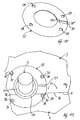
- the cross-sectional thickness of the sealing lip 17 is in comparison to the cross-sectional thickness of the retaining lip 18 small. This small cross-section of thickness makes it possible among other things, that the sealing lip 17 between the wall 2 and a separate clamping body 25 (Fig.7) with little effort can be immovably clamped and thereby the lead-through opening 7 absolutely sealed when assembled is.
- the clamping body 25 has in the illustrated embodiment the shape of an annular disc with a central sealing opening 26.
- This sealing opening 26 is circular and surrounds the spout 23.
- the sealing opening 26 is radial from surround a sealing edge 34 which has a radially inner Clamping web 27 and a radially outer contact web 28 comprises.
- the Inner diameter of the contact web 28 is slightly larger than that Outer diameter of the sealing lip 17 and is therefore fixed in the clamp Sealing lip 17 directly on the wall 2.
- the jetty 28 stands in the axial direction or in the direction of the central longitudinal axis 15 beyond the clamping web 27.
- This axial protrusion d enables axial and radial coverage at the same time the sealing lip 17. This in turn enables without additional Components provide good protection against damage for the sealing lip 17 and thus an effective seal of the through opening 7.
- the landing stage 28 is interposed with an additional one Layer (e.g. insulating or sealing layer) on the wall 2. This can further increase the sealing effect be improved.
- Layer e.g. insulating or sealing layer
- the clamping body 25 is designed such that the clamping web 27 in the assembled state on the lip surface 24 of the sealing lip 17 rests and it runs in the direction of implementation 8 Clamping force clamped (Fig. 6). To generate the clamping force clamping devices to be explained are provided. These clamping devices can the clamping body 25 in the direction 8 apply force so that the sealing edge 34, in particular the dock 28, pressed against the wall 2 and, if necessary the clamping means is compressed and the clamping web 27 on creates the lip surface 24. In a preferred embodiment the projection d is smaller than the axial cross-sectional thickness the sealing lip 17. This will seal the feed-through opening 7 reinforced with little effort.
- the contact web 28 is of a total of four in the axial direction or in the clamping force direction extending receiving channels 29 for receiving each penetrates a threaded bolt 30 which on the Partial wall 3 or 4 attached, e.g. is welded on (Fig. 9).
- a threaded bolt 30 which on the Partial wall 3 or 4 attached, e.g. is welded on (Fig. 9).
- Each two threaded bolts 30 are on a partial wall 3 or partial wall 4 attached, the central longitudinal axes of the threaded bolts 30 run at right angles to the wall plane of wall 2.
- the threaded bolts 30 have an external thread, not shown here and each correspond to an internal thread 35, which is part of a clamping element 36 (e.g. a Screw nut).
- the clamping element 36 is used during assembly of the clamping body 25 on the wall 2 facing away and over the Receiving channel 29 protruding free end of the threaded bolt 30 screwed on. By screwing on the clamping element 36 is the sealing lip 17 axially facing away from the surface annular sealing edge 34 of the clamp body 25 automatically loaded with a clamping force.
- the sealing edge 34 of the clamp body 25 is transverse to one its circumferential direction, i.e. radially extending slot 31 severed. This allows the clamp body 25 to be particularly easy to install to be applied to the wiring harness 1 as Clamping jaw for fixing the sealing lip 17 effectively his.
- the threaded bolts 30 and the receiving channels 29 can be arranged such that the slot 31 is not positioned at right angles to the parting line 32 between the two part walls 3, 4 during assembly .
- the slot 31 is positioned parallel to the parting line 32.
- the boundary section 33 then lies only against the partial wall 3, while the boundary section 33 ′ only abuts against the partial wall 4.
- the threaded bolts 30 are arranged so as to be distributed in the circumferential direction of the sealing lip 17 in such a way that the angular arc measure differs between adjacent threaded bolts. This Coding "ensures a clear functional position of the clamping body 25.
- the receiving channels 29 or the threaded bolts 30 are not arranged point-symmetrically to the center of the sealing opening 26. In a preferred embodiment, the receiving channels 29 or the threaded bolts 30 are mirror-symmetrical to the cutting line VIII-VIII arranged in Fig.7.
- the wiring harness 1 When assembling, the wiring harness 1 is first in the direction of insertion 20, i.e. transversely to the direction 8, in the partial opening 6 of the first partial wall 3 is used.
- the ring-shaped clamp body 25 can - but does not have to - at this point be applied to the wiring harness 1.
- the two Partial walls 3, 4 from the starting position approximately in the direction of implementation 8 approximated each other.
- the radius of the partial opening 6 'of the second partial wall 4 is larger is than the radius of the retaining lip 18, manufacturing and Due to the installation, there are dimensional tolerances between the components to be installed Components taken into account and the second partial wall 4 can in the implementation direction 8 to the first partial wall 3 without obstruction be introduced.
- This is for example with a automated manufacturing and especially in the modular construction of vehicles of great importance since here the Vehicle modules must be partially merged horizontally.
- the partial walls 3, 4 brought together overlap themselves with their edge segments 13, 13 'and are in the range of Edge segments 13, 13 'by means of a suitable connecting technique (e.g. spot welding) firmly connected.
- the clamping body 25 is first unscrewed. Are the partitions 3,4 releasably attached to each other (e.g. screwed together), then the partial walls 3, 4 separated from each other and then the wiring harness 1 becomes the insertion direction 20 pulled out of the partial opening 6 in the opposite direction.
- the wiring harness 1 preferably in the direction of displacement 21 through the Feed-through opening 7 moves and the holding lip 18 is made the feed-through opening 7 is knotted out.
- FIG. 10 shows the clamping body 25 in a further embodiment shown, the receiving channels 29 between the inner Clamping web 27 and an outer contact web 28 'arranged are.
- This outer contact web 28 ' is made considerably narrower as the corresponding landing stage 28 according to FIG. 7.
- the Contact web 28 ' is on the radially outer edge of the clamping body 25 limited.
- the clamping body 25 according to FIG. 10 is preferably made of metal, especially as a stamped or stamped part, manufactured.
- the receiving channels 29 are preferably the outer Contact web 28 'is closer in the radial direction than the inner one Clamping web 27. This will result in excessive crushing of the avoiding sealing lip 17 to be clamped during the assembly process.
- the partial wall 4 is cranked, i.e. she points between its edge segment 13 'and the rest of the area an offset 39. This will make the otherwise between both partial walls 3, 4 resulting surface jump 38 compensated.
- the two surfaces facing away from the edge segment 13 ' of the partial walls 3, 4 form the same surface level 40
- Area 41 formed in the bend 39 is preferred in the assembly of the sealing element, in particular of an elastic sealing lip 17 filled.
- the overlapping partial walls 3, 4 in the area of the edge segments 13, 13 ', heel-like Surface jump 38 compensated in that the sealing lip 17 facing side of the clamp body 25 a bevel 37, which is located directly on the sealing lip 17th creates.
- the compensation slope 37 preferably runs in one Angle w of about 45 ° compared to the immediately neighboring one Surface areas of the clamp body 25 or its sealing edge 34.
- the bevel 37 is on the clamping web 27, namely at the radially inner region thereof.
- the exact arrangement and the cross section of the bevel 37 on Clamping body 25 depends individually on the course of the surface crack 38 on the partial walls 3, 4 and the intended relative position of the clamping body 25 relative to the partial walls 3, 4.
- Fig. 13 runs the compensation slope 37 corresponding to the straight line Edge edges 5 of the partial wall 3 linearly in the manner of approximately one Chord along the clamp body 25.
Landscapes
- Engineering & Computer Science (AREA)
- Architecture (AREA)
- Civil Engineering (AREA)
- Structural Engineering (AREA)
- Mechanical Engineering (AREA)
- Installation Of Indoor Wiring (AREA)
- Media Introduction/Drainage Providing Device (AREA)
- Rigid Pipes And Flexible Pipes (AREA)
Abstract
Description
Die Erfindung betrifft eine Durchführung für eine Leitung durch eine Wand.The invention relates to a bushing for a line a wall.
Die Wand ist z.B. in einem Kraftfahrzeug angeordnet und hier
insbesondere als Wand zwischen Motorraum und Fahrgastraum eines
Fahrzeugs ausgestaltet. Leitungsbündel mit elektrischen Leitern
für Kraftfahrzeuge, wie sie aus DE 34 31 617 A1 und aus DE 37
40 582 A1 bekannt sind, werden üblicherweise durch eine die
Wand durchsetzende Durchführungsöffnung hindurchgeführt, indem
das Leitungsbündel und eine das Leitungsbündel umgebende Dichtungstülle
in Längsrichtung des Leitungsbündels durch die Öffnung
![]()
![]()
Um die Fädelarbeit durch die Stirnwand in einem Kraftfahrzeug
zu erleichtern, wird in DE 37 01 597 A1 vorgeschlagen, einen
Kabelbaum zunächst durch ein vergleichsweise großes Lenkungsdurchtrittsloch
zu fädeln, um danach den Kabelbaum in Radialrichtung
in das vergleichsweise kleine, mit dem Lenkungsdurchtrittsloch
durch einen Schlitz verbundene Kabeldurchtrittsloch
einzusetzen. Eine derartige Montage ist jedoch nur für den Spezialfall
möglich, daß ein Lenkungsdurchtrittsloch vorhanden
ist. In diesem Fall ist die vorbekannte Montage allerdings auch
nur dann sinnvoll, wenn der Kabelbaum in unmittelbarer Nähe der
Lenksäule durch die Stirnwand hindurchgeführt werden soll. Anderenfalls
steigt der Querschnitt des die Stirnwand durchsetzenden
Verbindungsschlitzes rasch an, so daß die Abdichtung des
Verbindungsschlitzes zwischen Kabel- und Lenkungsdurchtrittsloch
mit erhöhtem Aufwand und den daraus resultierenden, obengenannten
Nachteilen verbunden ist. Außerdem entsteht ein großer
Materialverschnitt beim Herstellen der Durchführungsöffnung.To the threading through the front wall in a motor vehicle
To facilitate, it is proposed in
Der Erfindung liegt die Aufgabe zugrunde, eine montagetechnisch einfache Durchführung für eine Leitung durch eine Wand zu schaffen.The invention has for its object a technical assembly easy implementation for a line through a wall too create.
Diese Aufgabe wird durch die Merkmalskombination der Ansprüche
1 und 7 gelöst.This task is accomplished through the combination of features of the
Erfindungsgemäß weist die Durchführung eine Wand auf, welche
mehrere Teilwände umfaßt. Diese Teilwände werden dann während
der Montage miteinander - je nach Anwendungsfall lösbar oder
unlösbar - fest verbunden. Vor der Befestigung der Teilwände
aneinander wird zunächst die Leitung quer zur Leitungslängsrichtung
in die randoffene Teilöffnung einer ersten Teilwand
eingesetzt. Danach wird mindestens eine zweite Teilwand, welche
ebenfalls eine randoffene Teilöffnung enthält, an der ersten
Teilwand befestigt. Dabei korrespondiert die randoffene Teilöffnung
dieser zweiten Teilwand mit der randoffenen Teilöffnung
der ersten Teilwand, so daß die Teilöffnungen gemeinsam in
eine randgeschlossene Durchführungsöffnung für die Leitung
Vorteilhaft wird jegliche Fädelarbeit bei der Montage der Leitung vermieden. Da die Leitung quer zur Leitungslängsrichtung in eine erste Teilöffnung eingesetzt wird und weitere Teilöffnungen zusätzlicher Teilwände nachträglich an die erste Teilwand angesetzt werden, können die Ränder der Teilöffnungen den Umfang der Leitung besonders dicht flankieren. Die Durchführungsöffnung der Wand ist deshalb im Gegensatz zu herkömmlichen Konstruktionen besonders klein gehalten. Folglich können Spalte zwischen Leitung und Durchführungsöffnung mit geringem Aufwand und einfacher Dichtungskonstruktion abgedichtet werden. Dieser Vorteil wiederum reduziert die Fertigungskosten und verbessert die Funktionssicherheit einer verwendeten Dichtung.Any threading work is advantageous when installing the line avoided. Since the line is transverse to the longitudinal direction of the line is inserted into a first partial opening and further partial openings additional partitions after the first part can be applied, the edges of the partial openings Flank the circumference of the line particularly tightly. The lead-through opening the wall is therefore in contrast to conventional ones Constructions kept particularly small. Hence, column between line and lead-through opening with little effort and simple seal construction can be sealed. This Advantage in turn reduces manufacturing costs and improves the functional reliability of a seal used.
Im Falle einer Abdichtung der beiden Seiten der Wand voneinander im Bereich der Durchführungsöffnung werden geeignete Dichtungselemente (z.B. Tüllen, Dichtungsringe, -scheiben) verwendet, welche z.B. unmittelbar bei der Herstellung der Leitung und/oder nachträglich als separate Bauteile am Umfang der Leitung fixiert werden können. Anstelle dieser Dichtungselemente kann der Bereich der Durchführungsöffnung auch durch Ausschäumen, Anvulkanisieren od. dgl. der Leitung abgedichtet werden.In case of sealing the two sides of the wall from each other Suitable sealing elements are located in the area of the lead-through opening (e.g. grommets, sealing rings, washers) used, which e.g. immediately during the production of the line and / or subsequently as separate components on the circumference of the line can be fixed. Instead of these sealing elements the area of the lead-through opening can also be foamed, Vulcanization or the like. The line are sealed.
In einer bevorzugten Ausführungsform sind die korrespondierenden Teilöffnungen unterschiedlich ausgebildet, wobei die Teilöffnung der ersten Teilwand vorzugsweise den größten Anteil des Öffnungsquerschnitts der Durchgangsöffnung aufweist, um die Montage der Leitung in der ersten Teilwand zu erleichtern.In a preferred embodiment, the corresponding ones Partial openings formed differently, the partial opening the first part wall preferably the largest proportion of the opening cross section of the through opening, around the To facilitate assembly of the line in the first partial wall.
Vorzugsweise setzt sich die Durchführungsöffnung - wie oben bereits erläutert - aus zwei Teilöffnungen zusammen, da in diesem Fall nur zwei Teilwände benötigt werden, um die Durchführung der Leitung zu realisieren. Auf diese Weise ist die Fertigung und die Montage der Leitungsdurchführung besonders einfach realisierbar.The feed-through opening preferably settles - as already above explained - from two partial openings together, because in this Case only two partitions are needed to carry out the line to realize. This is the way of manufacturing and the installation of the cable bushing is particularly easy to implement.
Es sei erwähnt, daß bei der Erfindung der Begriff
Zur Befestigung der beiden Teilwände aneinander können je nach Anwendungsfall unterschiedliche Befestigungsmittel vorgesehen sein. Als unlösbare Befestigung der Teilwände aneinander ist z.B. Kleben, Schweißen, Löten, Vernieten geeignet. Als lösbare Befestigung ist beispielsweise ein Verschrauben der Teilwände miteinander geeignet. Die Teilwände sind je nach Anwendungsfall vorzugsweise aus Metall oder Kunststoff hergestellt. Dabei können die Teilwände aus plattenartigen Tafeln oder Blechtafeln entsprechend der gewünschten Querschnittsform zugeschnitten werden. Die Teilwände können in einer weiteren bevorzugten Ausführungsform mittels Scharniere oder geeigneter Verbindungs-Bauteile miteinander lösbar oder unlösbar miteinander verbunden sein.To attach the two partitions to each other, depending on Use case different fasteners provided his. As an inseparable attachment of the part walls to each other e.g. Suitable for gluing, welding, soldering, riveting. As releasable Fastening is, for example, screwing the part walls together suitable with each other. The partitions are depending on the application preferably made of metal or plastic. You can the partial walls made of plate-like panels or sheet metal cut according to the desired cross-sectional shape become. In a further preferred embodiment, the partial walls can by means of hinges or suitable connecting components releasably or permanently connected to each other his.
Die Maßnahme nach Anspruch 2 ermöglicht eine gute Anpassung der
Durchführungsöffnung an den oftmals kreisartigen oder ovalen
Querschnitt der Leitung oder einer die Leitung umgebenden Dichtungs-Tülle.
So kann ein Aussparungsrand einer Aussparung bzw.
einer Teilöffnung die Leitung etwa bündig oder mit verhältnismäßig
geringem Radialabstand umgeben. Dadurch sind etwaige
Dichtungsprobleme weiter reduziert. Außerdem kann die Leitung
ohne besonderen Montageaufwand von dem Aussparungsrand der Teilöffnung
einer ersten Teilwand vorfixiert werden, nachdem die
Leitung in diese Teilöffnung eingesetzt worden ist. Dabei kann
die Umrißform eines Öffnungsrand-Abschnittes ein etwas verkleinertes
Abbild des zu umfassenden Querschnittes der Leitung bzw.
der Tülle sein, um eine zuverlässige Vorfixierung der Leitung
zu unterstützen. Hierzu ist die Tülle vorzugsweise elastisch
ausgebildet.The measure according to
Die Ansprüche 3 und 4 verbessern die Fixierung der Leitung während
der Montage der Teilwände. Die in eine Teilöffnung eingesetzte
Leitung wird von dem sich in Richtung der Randkante der
Teilwand verjüngenden Aussparungsrand an einem Herausfallen aus
der Teilöffnung gehindert. Die Leitung liegt gewissermaßen verrastet
in der Teilwand ein. Hierbei kann davon ausgegangen werden,
daß der Leitungsmantel oder ein den Leitungsmantel umgebendes
Dichtungselement (z.B. Dichtungs-Tülle) eine Eigenelastizität
aufweist, wodurch die Leitung in die verjüngte
Randaussparung eingesetzt wird, ohne beschädigt zu werden.
Vorzugsweise ist die lichte Weite (= Öffnungsweite) der Teilöffnung im Bereich der Randkante kleiner als die größte lichte Weite der Teilöffnung, die parallel zur Öffnungsweite verläuft. Hierdurch lassen sich die obengenannten Vorteile fertigungstechnisch einfach dadurch erzielen, indem in zumindest eine Teilwand ein kreisbogenförmiger Aussparungsrand eingearbeitet, z.B. gebohrt oder gestanzt wird. Dabei überspannt der Aussparungsrand ein geeignetes Kreisbogenmaß,welches größer als 180° und kleiner als 360° ist. Damit ist einerseits eine bedienungsfreundliche Montage der Leitung gewährleistet. Andererseits flankiert der Aussparungsrand selbst bereits die Leitung verhältnismäßig dicht, so daß aufwendige Abdichtungsmaßnahmen entfallen können.The inside width (= opening width) of the partial opening is preferably smaller than the largest clear edge in the area of the edge Width of the partial opening that runs parallel to the opening width. This allows the above-mentioned advantages in terms of production technology simply by putting in at least one Part of a circular arc-shaped recess edge, e.g. is drilled or punched. The recess edge spans a suitable circular arc dimension, which is larger than 180 ° and is less than 360 °. On the one hand, this is easy to use Assembly of the line guaranteed. On the other hand the recess edge itself already flanked the line proportionally tight, so that complex sealing measures are not necessary can.
Gemäß Anspruch 5 liegen benachbarte Teilwände im zusammengebauten
Zustand der Wand überlappt aneinander an und fördern durch
diese Relativlage die Eigenstabilität der Wand. Die derart gebildete
labyrinthartige Trennfuge zwischen den beiden Seiten
der Wand verbessert gegenüber einer einfachen stirnseitigen Anlage
der Randkanten benachbarter Teilwände auch die Dichtigkeit
der Wand.According to
Nach Anspruch 6 ist der Aussparungsrand der ersten Teilwand vom Aussparungsrand mindestens einer weiteren Teilwand quer zur Durchführungsrichtung - sie entspricht etwa der Leitungslängsrichtung im Bereich der Wand - mit Abstand umgeben, um Montagetoleranzen und Maßtoleranzen von Bestandteilen der Durchführung berücksichtigen zu können. Hierdurch kann die zweite Teilwand und ggfs. weitere Teilwände behinderungsfrei an die erste Teilwand herangeführt (richtungsmäßig insbesondere etwa parallel und/oder rechtwinklig zur Wandebene) und daran befestigt werden, selbst wenn der Umfangsmantel der Leitung von einer Dichtungs-Tülle und/oder anderen Dichtungselementen umgeben ist. Dieser Vorteil unterstützt eine automatisierte Fertigung der Durchführung.According to claim 6, the recess edge of the first partial wall is from Recessing edge of at least one other partial wall transverse to Execution direction - it corresponds approximately to the longitudinal direction of the line in the area of the wall - surrounded at a distance to allow assembly tolerances and dimensional tolerances of components of the implementation to be able to take into account. This allows the second part of the wall and, if necessary, other partial walls to the first partial wall without hindrance introduced (directionally in particular approximately parallel and / or perpendicular to the wall plane) and attached to it, even if the circumferential jacket of the pipe from a sealing grommet and / or other sealing elements is surrounded. This advantage supports automated production of the Execution.
Die Erfindung umfaßt weiterhin eine konstruktiv einfach gestaltete
Abdichtung. Der für sich selbst erfinderische Anspruch 7
schlägt ein mit einem Klemmkörper zusammenwirkendes Dichtungselement
vor, um eine Durchführungsöffnung in einer Wand zum
Durchführen einer Leitung abzudichten. Die Abdichtung kann entweder
allein mittels des Klemmkörpers und des Dichtungselementes
oder in Kombination mit weiteren Dichtungsteilen erfolgen.
Die Abdichtung wird vorzugsweise dadurch unterstützt, indem das
Dichtungselement (z.B. als Tülle ausgestaltet) den Umfangsmantel
der Leitung dicht umgibt. Hierzu ist das Dichtungselement
vorzugsweise elastisch ausgebildet und liegt zur Abdichtung
z.B. nach Art eines Preßsitzes am Umfangsmantel an oder ist mit
dem Umfangsmantel einstückig verbunden.The invention further includes a structurally simple design
Seal.
Die Abdichtung mittels Dichtungselement und Klemmkörper gemäß
Anspruch 7 muß - wie bereits gesagt - nicht notwendigerweise
bei einer Wand und Durchführungsöffnung gemäß Anspruch 1 eingesetzt
werden. Vielmehr ist die vorgenannte Abdichtungs-Konstruktion
sowohl für einteilige Wände mit einer randgeschlossenen
oder randoffenen Durchführungsöffnung als auch für
die mehrteilige Wand gemäß Anspruch 1 geeignet.The sealing by means of a sealing element and sprag according to
Vorzugsweise sind die Dichtlippe des Dichtungselementes und der Klemmkörper im Querschnitt kreisförmig ausgebildet, wodurch entlang des Öffnungsrandes einer Durchführungsöffnung auf konstruktiv einfache Weise eine gleichmäßige Abdichtung erzielt wird. Andere Querschnitte, wie beispielsweise oval, dreieckig, rechteckig oder allgemein polygonförmig, können jedoch ebenfalls verwendet und abhängig von dem Querschnitt der Durchführungsöffnung und/oder der Leitung ausgewählt werden. Preferably, the sealing lip of the sealing element and the Clamping body circular in cross section, whereby along the opening edge of a through opening on constructive easily achieved a uniform seal becomes. Other cross sections, such as oval, triangular, rectangular or generally polygonal, but can also used and depending on the cross section of the through opening and / or the line can be selected.
Die Wand und der Klemmkörper korrespondieren klemmbackenartig miteinander und bewirken hierdurch eine besonders stabile Lagerung des Dichtungselementes und seiner Dichtlippe an der Wand. Vorzugsweise wird die Klemmkraft mittels geeigneter Spannmittel erzielt. Die auf die Dichtlippe ausgeübte Klemmkraft erhöht die Dichtungswirkung des Dichtungselementes zusätzlich.The wall and the clamping body correspond like a jaw with each other and thereby cause a particularly stable storage of the sealing element and its sealing lip on the wall. The clamping force is preferably by means of suitable clamping means achieved. The clamping force exerted on the sealing lip increases the Sealing effect of the sealing element in addition.
Die Ansprüche 8 bis 11 unterstützen eine mechanisch stabile
Klemmfixierung des Dichtungselementes. Dabei ist eine wirksame
Klemmfixierung des Dichtungselementes mit konstruktiv einfachen
und kostengünstigen Spannmitteln gegeben. Die hierbei vorzugsweise
verwendeten Gewindebolzen können bei entsprechender Anordnung
an der Wand bzw. den Teilwänden in einer Doppelfunktion
als Außengewinde und auch als Schweißbolzen eingesetzt werden.The
Die Maßnahme nach Anspruch 12 verbessert die Abdichtung des
Überlappungsbereiches der sich überlappenden Teilwände kostengünstig
und fertigungstechnisch unaufwendig. Der Oberflächensprung
im Überlappungsbereich wird durch eine Ausgleichschräge
des Klemmkörpers ausgeglichen. Der Querschnitt der Ausgleichschräge
ist in geeigneter Weise an den Oberflächensprung angepaßt,
um eine wirksame Klemmung des Dichtungselements und Abdichtung
zu erzielen. Vorzugsweise verläuft die Ausgleichschräge
konstruktiv einfach in einer einzigen Ebene. Insbesondere
schließt die Ausgleichschräge einen Winkel von etwa 45° mit dem
unmittelbar benachbarten Oberflächenbereich des Klemmkörpers
ein. Mittels der Ausgleichschräge wird vermieden, daß eine
Teilwand aufwendig um den Betrag der Wandstärke einer anderen
Teilwand abgekröpft werden muß, um dasselbe Oberflächenniveau
für eine gute Abdichtung zu erzielen. Eine aufwendige Abstimmung
der Teilwände entfällt demnach. Außerdem werden durch die
Abkröpfung entstehende Rinnen oder Fugen zwischen den Teilwänden
vermieden, welche durch das Dichtungselement möglichst
vollständig ausgefüllt werden müßten.The measure according to
Alternativ ist es jedoch auch möglich, auf die Ausgleichschräge am Klemmkörper zugunsten der vorgenannten Abkröpfung zu verzichten, wenn eine Abkröpfung der einen Teilwand für eine ausreichende Abdichtung durch das Dichtungselement sinnvoll erscheint.Alternatively, however, it is also possible to use the compensation slope to dispense with the clamping body in favor of the aforementioned offset, if a bend in one part of the wall is sufficient Sealing by the sealing element seems reasonable.
Der Klemmkörper ist vorzugsweise metallisch, z.B. aus Stahl oder Federstahlblech, hergestellt. Ein kostengünstiges Flachmaterial, insbesondere aus Metallblech, ist ebenfalls geeignet. In einer bevorzugten Ausführungsform wird der Klemmkörper aus dem Metallblech einstückig als Stanzzieh- oder Stanzprägeteil gefertigt. Der mit einer zentralen Dichtöffnung versehene Klemmkörper in den vorgenannten metallischen Ausführungsformen hat den Vorteil, daß erhöhte Anforderungen an ein montagefreundliches Einfädeln einer Leitung oder auch mehrerer Leitungen bzw. Kabelstränge in die Dichtöffnung erfüllt werden.The clamp body is preferably metallic, e.g. from steel or spring steel sheet. An inexpensive flat material, in particular from sheet metal, is also suitable. In a preferred embodiment, the clamping body is made of the metal sheet in one piece as a stamped or stamped part manufactured. The one with a central sealing opening Clamping body in the aforementioned metallic embodiments has the advantage that increased requirements for an easy to assemble Threading one or more lines or cable harnesses in the sealing opening.
Der Klemmkörper kann auch kostengünstig aus einem geeigneten Kunststoff hergestellt sein. Der Kunststoff kann je nach Anwendungsfall elastisch oder im wesentlichen unelastisch sein.The clamp body can also be inexpensive from a suitable Be made of plastic. Depending on the application, the plastic can be elastic or substantially inelastic.
Die Maßnahmen nach den Ansprüchen 13 und 14 erlauben eine gekapselte
Anordnung der die eigentliche Abdichtung bewirkenden
Dichtlippe innerhalb des Klemmkörpers. Hierdurch ist das Dichtungselement
wirksam vor Beschädigungen und Umgebungseinflüssen
geschützt. Eine konstante Dichtungswirkung über eine lange Betriebsdauer
hinweg ist gewährleistet. Vorzugsweise ist die zu
klemmfixierende Dichtlippe hinsichtlich ihrer Querschnittsstärke
bzw. Dicke im Ausgangszustand größer als der in Klemmrichtung
verlaufende Abstand zwischen einem äußeren Anlagesteg und
einem demgegenüber inneren Klemmsteg des Klemmkörpers. Diese
geometrischen Verhältnisse ermöglichen mit geringem Kraftaufwand
eine zusätzliche Klemmung oder Pressung der Dichtlippe gegen
die Wand mit einer entsprechend höheren Dichtungswirkung.
Vorteilhaft werden für die Montage mehrere Typen von Klemmkörpern
vorgehalten, welche sich im wesentlichen nur hinsichtlich
des Abstandes zwischen äußerem Anlagesteg und innerem Klemmsteg
unterscheiden. Somit kann bei gleichbleibend einfacher Montage
je nach Anwendungsfall eine andere gewünschte Klemmkraft für
die Klemmfixierung der Dichtlippe erzielt werden. In weiteren
Ausführungsformen kann es für eine geeignete Klemmfixierung
ausreichend sein, auf den vorgenannten Abstand zwischen äußerem
Anlagesteg und innerem Klemmsteg gegenüber der Dichtlippe zu
verzichten. Es kann auch auf den Anlagesteg verzichtet werden,
so daß der Dichtungsrand nur einen Klemmsteg zur Fixierung der
Dichtlippe aufweist.The measures according to
Der gemäß Anspruch 16 geschlitzte Klemmkörper vereinfacht die
Montage der Durchführung, indem der Klemmkörper einfach durch
Aufspreizen auf die Leitung aufgesetzt wird. Dieser Montageschritt
kann auch bereits beim Hersteller der Leitung erfolgen.
Zudem weist der geschlitzte Klemmkörper eine verbesserte Flexibilität
auf und kann gezielt einen Ebenensprung bzw. Oberflächensprung
der überlappt aneinander anliegenden Teilwände ausgleichen,
wenn der Schlitz parallel zu einer überlappten Randkante
einer Teilwand verläuft und die zwei beiderseits des
Schlitzes angeordneten Bereiche des Dichtungsrandes jeweils nur
an einer Teilwand (unter Zwischenlage der Dichtlippe) anliegen.The slotted clamping body according to
Gemäß den Ansprüchen 17 und 18 ist die Leitung mittels einer in
Umfangsrichtung der Leitung verlaufenden und an dem Dichtungselement
angebrachten Fixiernut besonders montagefreundlich in
eine erste Teilwand einsetzbar, wenn die Wand aus mehreren
Teilwänden mit jeweils einer Teilöffnung besteht. Die Fixiernut
ist vorzugsweise in vorgenannter Umfangsrichtung in sich geschlossen,
so daß eine größtmögliche Variabilität bei der Montage
der Leitung gegeben ist.According to
Grundsätzlich kann die erfindungsgemäße Durchführung der Leitung bei sämtlichen Trennwänden angewandt werden. Ein bevorzugtes Anwendungsgebiet ist allerdings der Fahrzeugbau (Anspruch 19), bei dem eine Reihe von Wand- oder Karosseriedurchbrüchen für Kabelsätze und andere Leitungen berücksichtigt werden müssen. Hier wirkt sich die mit der erfindungsgemäßen Leitungsdurchführung erzielte Montagevereinfachung besonders zeit- und kostensparend aus. Bei Kraftfahrzeugen existieren Trennwände z.B. zwischen Motorraum und Fahrgastraum - die sogenannte Stirnwand - oder zwischen Fahrgastraum und Heckraum, welche von Leitungen durchquert werden. Dabei kommt die erfindungsgemäße Leitungsdurchführung den Bedürfnissen des Rohbaus der Fahrzeuge entgegen, indem eine baukastenartige, modulare Montage des Rohbaus aus mehreren Modulen (z.B. Vorbaumodul, Fahrgastzelle, Fahrzeugdach, Heck) unterstützt wird. Dabei ist beispielsweise an den im Bereich einer Wand miteinander korrespondierenden Modulen jeweils eine Teilwand befestigt. Diese Teilwände werden dann beim Zusammenbau der Module automatisch miteinander zusammengeführt und fest verbunden (z.B. durch Kleben, Schweißen, Verschrauben), nachdem die Leitung in einem Zwischenschritt in die erste Teilwand eingesetzt worden ist. Bei einer weiteren Ausführungsform wird die Leitung ebenfalls in eine einem Kraftfahrzeug-Modul zugeordnete erste Teilwand eingesetzt und danach wird die zweite Teilwand (noch ohne Modul) und ggfs. weitere Teilwände an der ersten Teilwand befestigt. Das derart mit mindestens einer weiteren Teilwand ergänzte Modul wird daraufhin mit einem weiteren Modul zusammengeführt.Basically, the implementation of the line according to the invention can be applied to all partitions. A preferred one However, the area of application is vehicle construction (claim 19), where a series of wall or body openings for cable sets and other lines must be taken into account. This has an effect here with the line bushing according to the invention achieved simplification of assembly particularly time and cost-saving. Partitions exist in motor vehicles e.g. between engine compartment and passenger compartment - the so-called Bulkhead - or between the passenger compartment and the rear compartment, which of Lines are crossed. Here comes the invention Cable routing to meet the needs of the bodyshell of the vehicles counter by a modular, modular assembly of the shell from several modules (e.g. front module, passenger compartment, Vehicle roof, rear) is supported. Here is for example on the corresponding modules in the area of a wall one partial wall each attached. These partial walls will be then automatically merged when the modules are assembled and firmly connected (e.g. by gluing, welding, Screw) after the line in an intermediate step the first part of the wall has been inserted. Another Embodiment is also the line in a motor vehicle module assigned first partial wall inserted and then the second part wall (still without module) and, if necessary, others Partial walls attached to the first partial wall. That with at least a further sub-wall is added merged with another module.
Vorzugsweise wird zunächst die Leitung etwa quer zur Durchführungsrichtung in eine eine Randkante einer ersten Teilwand unterbrechende, als Teilöffnung wirksame Aussparung eingesetzt. Danach wird mindestens eine weitere Teilwand mit einer Teilöffnung an die erste Teilwand herangeführt und daran befestigt. Dabei nehmen die Teilwände eine derartige Relativlage zueinander ein, daß die miteinander korrespondierenden Teilöffnungen gemeinsam die Durchführungsöffnung bilden.Preferably, the line is initially approximately transverse to the direction of implementation into an edge edge of a first partial wall, effective recess used as partial opening. After that, at least one other partial wall with a partial opening brought up to the first partial wall and attached to it. The partial walls take such a relative position to each other a that the mutually corresponding partial openings together form the lead-through opening.
Je nach Anwendungsfall und vorgegebenen Raumverhältnissen ist es vorteilhaft, daß die Montagerichtung beim Heranführen der Teilwände aneinander quer zur Wandebene und/oder parallel zur Wandebene verläuft.Depending on the application and the given space it is advantageous that the mounting direction when the Partitions against each other transversely to the wall plane and / or parallel to Wall level runs.
Die Erfindung wird anhand der in den Figuren dargestellten Ausführungsbeispiele näher erläutert. Es zeigen:
- Fig. 1
- eine Explosionsdarstellung der erfindungsgemäßen Durchführung mit zwei Teilwänden,
- Fig. 2
- eine Explosionsdarstellung der erfindungsgemäßen Durchführung mit einer Leitung und mit einer Teilwand,
- Fig. 3
- eine perspektivische Vorderansicht der aneinander befestigten Seitenwände mit durchgeführter Leitung,
- Fig. 4
- eine perspektivische Rückansicht der aneinander befestigten Seitenwände mit durchgeführter Leitung etwa in Blickrichtung IV gemäß Fig.3,
- Fig. 5
- eine Seitenansicht auf einen eine Tülle als Dichtungselement tragenden Leitungsabschnitt der Leitung,
- Fig. 6
- eine teilweise geschnittene Seitenansicht auf die Durchführung mit dem Leitungsabschnitt gemäß Fig.5,
- Fig. 7
- eine Draufsicht auf einen mit der Tülle zusammenwirkendes Klemmkörper,
- Fig. 8
- eine Schnittansicht des Klemmkörpers gemäß Schnittlinie VIII-VIII in Fig.7,
- Fig. 9
- eine perspektivische Darstellung der Durchführung etwa gemäß Fig.3, jedoch mit an der Wand fixiertem Klemmkörper gemäß Fig.7,
- Fig. 10
- eine perspektivische Darstellung einer weiteren Ausführungsform des Klemmkörpers,
- Fig. 11
- eine geschnittene Seitenansicht der beiden Teilwände, wobei eine Teilwand abgekröpft ist,
- Fig. 12
- eine geschnittene Ansicht des mit einer Ausgleichschräge versehenen Klemmkörpers in einer weiteren Ausführungsform und
- Fig. 13
- eine Draufsicht auf die Durchführung mit einer Ausgleichschräge am Klemmkörper.
- Fig. 1
- an exploded view of the implementation according to the invention with two part walls,
- Fig. 2
- 2 shows an exploded view of the bushing according to the invention with a line and with a partial wall,
- Fig. 3
- 2 shows a perspective front view of the side walls fastened to one another with a lead through,
- Fig. 4
- 3 shows a perspective rear view of the side walls fastened to one another with the line carried through, approximately in viewing direction IV according to FIG. 3,
- Fig. 5
- 2 shows a side view of a line section of the line carrying a grommet as a sealing element,
- Fig. 6
- 3 shows a partially sectioned side view of the bushing with the line section according to FIG. 5,
- Fig. 7
- a plan view of a clamping body interacting with the spout,
- Fig. 8
- 2 shows a sectional view of the clamping body according to section line VIII-VIII in FIG. 7,
- Fig. 9
- 3 shows a perspective representation of the implementation, for example according to FIG. 3, but with the clamping body fixed to the wall according to FIG.
- Fig. 10
- 2 shows a perspective illustration of a further embodiment of the clamping body,
- Fig. 11
- 2 shows a sectional side view of the two partial walls, one partial wall being bent,
- Fig. 12
- a sectional view of the clamping body provided with a bevel in a further embodiment and
- Fig. 13
- a plan view of the implementation with a bevel on the clamping body.
Eine Leitung in Form eines Kabelbaumes 1 wird durch eine Wand 2
hindurchgeführt, welche zwei miteinander korrespondierende und
aneinander zu befestigende Teilwände 3 und 4 umfaßt (Fig.1).
Beispielsweise handelt es sich bei der Wand 2 um die Stirnwand
eines Kraftfahrzeuges, wobei die erste Teilwand 3 Bestandteil
der Fahrgastzelle und die zweite Teilwand 4 Bestandteil des
Vorbaumoduls sein kann. Die erste Teilwand 3 weist eine Randkante
5 auf, welche von einer als erste Teilöffnung 6 wirksamen
Aussparung unterbrochen ist. Die zweite Teilwand 4 weist ebenfalls
eine Randkante 5' auf, die von einer als zweiten Teilöffnung
6' wirksamen Aussparung unterbrochen ist. Beide Teilöffnungen
6,6' bilden gemeinsam eine Durchführungsöffnung 7, welche
die Wand 2 etwa in Leitungslängsrichtung bzw. Durchführungsrichtung
8 oder mit anderen Worten quer zur Wandebene der
Wand 2 durchsetzt (Fig.2).A line in the form of a
Die Aussparungsränder 9,9' beider Teilöffnungen 6,6' verlaufen
kreisbogenförmig und sind bei aneinander befestigten Teilwänden
3,4 mit ihren Konkavseiten einander zugewandt. Die beiden Aussparungsränder
9,9' unterscheiden sich voneinander durch ihren
Radius und ihr Winkelmaß. Der Aussparungsrand 9 der ersten Teilöffnung
6 überspannt einen Kreisbogen von mehr als 180°, so
daß der Querschnitt der ersten Teilöffnung 6 in Richtung der
unterbrochenen Randkante 5 verjüngt ausgebildet ist. Diese geometrische
Ausgestaltung bewirkt zwei etwa keilförmig verlaufende
Übergangsbereiche 10 der Teilwand 3 mit der Randkante 5 und
dem Aussparungsrand 9 als Keilschenkel. Diese Übergangsbereiche
10 sind als Arretier- oder Rückhaltemittel gegen ein unerwünschtes
Herausfallen des Kabelbaumes 1 wirksam, wenn der Kabelbaum
1 in die Teilöffnung 6 eingesetzt worden ist. Hierzu
ist die Teilöffnung 6 derart dimensioniert, daß der Aussparungsrand
9 am Umfangsmantel 11 des Kabelbaumes 1 bzw. an einem
den Umfangsmantel 11 umgebenden und noch zu erläuternden Dichtungselement
in Form einer Dichtungs-Tülle 12 etwa bündig anliegt.
Die die Unterbrechung der Randkante 5 bildende lichte
Öffnungsweite w zwischen den beiden Übergangsbereichen 10 ist
deshalb kleiner als der Durchmesser des Kabelbaumes 1 bzw. als
der Durchmesser des vom Aussparungsrand 9 umfaßten Bereiches
der Tülle 12.The recess edges 9.9 'of both partial openings 6.6' run
arcuate and are with part walls attached to each other
3, 4 with their concave sides facing each other. The two
Fig.3 ist der Befestigungszustand der beiden Teilwände 3,4 entnehmbar.
Dabei überlappen sich die beiden Teilwände 3 und 4 mit
ihren Aussparungsrändern 9,9' sowie mit Randsegmenten 13,13'
und liegen mit diesen Randsegmenten 13,13' planparallel aneinander
an (Fig.3, Fig.4). Der Teilwand 3 sind Randsegmente 13
zugeordnet, welche dem Aussparungsrand 9 und den Übergangsbereichen
10 benachbart etwa in Richtung der Randkante 5 verlaufen.
Die der Teilwand 4 zugeordneten Randsegmente 13' sind dem
Aussparungsrand 9' benachbart und verlaufen etwa in Richtung
der Randkante 5'. Im Bereich der gegenseitigen Überlappung sind
die Teilwände 3,4 aneinander befestigt, z.B. durch Verschweißen,
insbesondere Punktschweißen. Dies ist beispielsweise in
Fig.3 mittels der Schweißpunkte 14 angedeutet.3 shows the state of attachment of the two
Im Befestigungszustand der beiden Teilwände 3,4 sind die Aussparungsränder
9,9' etwa konzentrisch zur Mittellängsachse 15
der rotationssymmetrischen Tülle 12 angeordnet. Die Mittellängsachse
15 verläuft dabei etwa quer bzw. rechtwinklig zur
Wandebene der Wand 2. Die Teilöffnung 6' hat einen größeren Radius
als die Teilöffnung 6, so daß die beiden der Randkante 5'
benachbarten Randabschnitte 16 des Aussparungsrandes 9' die
Teilwand 3 überlappen und den Aussparungsrand 9 quer zur Mittellängsachse
15 des Kabelbaumes 1 mit Radialabstand umgeben
(Fig.4).The recessed edges are in the fastening state of the two
Die zumindest teilweise, vorzugsweise jedoch vollständig elastische
Tülle 12 umfaßt den Umfangsmantel 11 des Kabelbaumes 1
dicht (Fig.3). Die Tülle 12 kann einstückig (z.B. stoffschlüssig)
mit dem Umfangsmantel 11 verbunden sein oder ist als separates
Bauelement auf den Kabelbaum 1 aufgebracht. Die Tülle 12
trägt zwei in Durchführungsrichtung 8 voneinander beabstandete
und bezüglich der Mittellängsachse 15 konzentrisch zueinander
angeordnete Lippen. Die als Dichtlippe 17 wirksame Lippe hat
einen größeren Durchmesser als die zweite Lippe, die als Haltelippe
18 bezeichnet ist. Der in Richtung der Mittellängsachse
15 verlaufende Dicken-Querschnitt der beiden Lippen ist ebenfalls
unterschiedlich, wobei die Haltelippe 18 den größeren
Dicken-Querschnitt aufweist. Die beiden Lippen 17,18 begrenzen
eine in Umfangsrichtung des Kabelbaumes 1 verlaufende, ringförmig
in sich geschlossene Fixiernut 19. Deren parallel zur Mittellängsachse
15 angeordnete Nutbreite b ist größer als die Materialstärke
der Teilwand 3 bzw. des in der Fixiernut 19 einliegenden
Aussparungsrandes 9 (Fig.5). Der Kabelbaum 1 läßt
sich deshalb zusammen mit der Tülle 12 montagefreundlich mit
viel Bewegungsspielraum radial zur Leitungslängsrichtung 8 in
die Teilöffnung 6 einsetzen. Die Einsetzrichtung 20 ist in
Fig.2 dargestellt.The at least partially, but preferably completely
Die Haltelippe 18 ist derart dimensioniert, daß sie die Teilöffnung
6 der ersten Teilwand 3 nach dem Einsetzen des Kabelbaumes
1 abdeckt. Aufgrund ihres verhältnismäßig großen Dicken-Querschnitts
entlang der Mittellängsachse 15 weist die Haltelippe
18 trotz elastischer Eigenschaften eine gewisse Eigensteifigkeit
auf, welche ein allzuleichtes Umbiegen der radial
äußeren Segmente der Haltelippe 18 verhindert. Die Haltelippe
18 ist deshalb als Axialsicherung gegen ein Herausziehen
oder Herausschieben des Kabelbaumes 1 aus der ersten Teilwand 3
in Verschieberichtung 21 wirksam. In Gegenverschieberichtung 22
ist ein Entfernen des Kabelbaumes 1 aus seiner Montage-Sollstellung
vor allem durch einen Tüllenansatz 23 verhindert,
dessen entlang der Mittellängsachse 15 verlaufender Dicken-Querschnitt
verhältnismäßig groß ist - im vorliegenden Ausführungsbeispiel
mehr als doppelt so groß wie der entsprechende
Querschnitt der Haltelippe 18 - und deshalb ebenfalls gegen ein
allzuleichtes Umbiegen oder eine Kompression geschützt ist.
Dieser Tüllenansatz 23 ist konzentrisch zur Mittellängsachse 15
angeordnet und einstückig mit der Dichtlippe 17 verbunden. Dabei
grenzt der Tüllenansatz 23 unmittelbar an der der Haltelippe
18 abgewandten Lippenoberfläche 24 der Dichtlippe 17 an. Der
Tüllenansatz 23 hat einen kegelstumpfförmigen Querschnitt, dessen
größter Kegelstumpfdurchmesser der Lippenoberfläche 24 zugewandt
ist. Dieser größte Kegelstumpfdurchmesser ist kleiner
als der Durchmesser der Haltelippe 18. Der Querschnitt des Tüllenansatzes
23 verjüngt sich ausgehend von der Lippenoberfläche
24 in Durchführungsrichtung 8 bzw. in Verschieberichtung 21.The holding
Die Dichtlippe 17 hat im Gegensatz zur Haltelippe 18 die eigentliche
Abdichtungsfunktion. Sie hat einen größeren Radius
als die Haltelippe 18 und steht im Montagezustand über den Öffnungsrand
der Durchführungsöffnung 7 hinaus, der von beiden
Aussparungsrändern 9,9' und einem von der zweiten Teilwand 4
nicht abgedeckten Abschnitt der Randkante 5 der ersten Teilwand
3 gebildet wird. Die Querschnittsstärke der Dichtlippe 17 ist
im Vergleich zur Querschnittsstärke der Haltelippe 18 verhältnismäßig
klein. Dieser kleine Dicken-Querschnitt ermöglicht es
unter anderem, daß die Dichtlippe 17 zwischen der Wand 2 und
einem separaten Klemmkörper 25 (Fig.7) mit geringem Kraftaufwand
unbeweglich klemmfixierbar ist und hierdurch die Durchführungsöffnung
7 im Montagezustand absolut dicht verschlossen
ist.In contrast to the holding
Der Klemmkörper 25 hat in dem dargestellten Ausführungsbeispiel
die Form einer ringförmigen Scheibe mit einer zentralen Dichtöffnung
26. Diese Dichtöffnung 26 ist kreisrund ausgebildet und
umgibt den Tüllenansatz 23. Die Dichtöffnung 26 ist radial von
einem Dichtungsrand 34 umgeben, welcher einen radial inneren
Klemmsteg 27 und einen radial äußeren Anlagesteg 28 umfaßt. Der
Innendurchmesser des Anlagesteges 28 ist etwas größer als der
Außendurchmesser der Dichtlippe 17 und liegt deshalb bei klemmfixierter
Dichtlippe 17 unmittelbar an der Wand 2 an. Der Anlagesteg
28 steht in Axialrichtung bzw. in Richtung der Mittellängsachse
15 über den Klemmsteg 27 hinaus. Dieser axiale Überstand
d ermöglicht eine axiale und gleichzeitig radiale Abdeckung
der Dichtlippe 17. Dies wiederum ermöglicht ohne zusätzliche
Bauteile einen guten Beschädigungsschutz für die Dichtlippe
17 und somit eine wirksame Abdichtung der Durchführungsöffnung
7.The clamping
Alternativ liegt der Anlagesteg 28 unter Zwischenlage einer zusätzlichen
Schicht (z.B. isolierende oder abdichtende Schicht)
an der Wand 2 an. Hierdurch kann die Dichtungswirkung weiter
verbessert werden.Alternatively, the
Der Klemmkörper 25 ist derart ausgestaltet, daß der Klemmsteg
27 im Montagezustand an der Lippenoberfläche 24 der Dichtlippe
17 anliegt und sie mit in Durchführungsrichtung 8 verlaufender
Klemmkraft klemmfixiert (Fig.6). Zur Erzeugung der Klemmkraft
sind noch zu erläuternde Spannmittel vorgesehen. Diese Spannmittel
können den Klemmkörper 25 in Durchführungsrichtung 8
kraftbeaufschlagen, so daß der Dichtungsrand 34, insbesondere
der Anlagesteg 28, an die Wand 2 gepreßt und dabei ggfs. von
den Spannmitteln komprimiert wird und sich der Klemmsteg 27 an
die Lippenoberfläche 24 anlegt. In einer bevorzugten Ausführungsform
ist der Überstand d kleiner als die axiale Querschnittsstärke
der Dichtlippe 17. Hierdurch wird die Abdichtung
der Durchführungsöffnung 7 mit geringem Kraftaufwand verstärkt.The clamping
Der Anlagesteg 28 ist von insgesamt vier in Axialrichtung bzw.
in Klemmkraftrichtung verlaufenden Aufnahmekanälen 29 zur Aufnahme
jeweils eines Gewindebolzens 30 durchsetzt, der an der
Teilwand 3 bzw. 4 befestigt, z.B. angeschweißt ist (Fig.9). Jeweils
zwei Gewindebolzen 30 sind an einer Teilwand 3 oder Teilwand
4 befestigt, wobei die Mittellängsachsen der Gewindebolzen
30 rechtwinklig zur Wandebene der Wand 2 verlaufen. Die Gewindebolzen
30 weisen ein hier nicht näher dargestelltes Außengewinde
auf und korrespondieren jeweils mit einem Innengewinde
35, welches Bestandteil eines Spannelementes 36 (z.B. eine
Schraubenmutter) ist. Das Spannelement 36 wird bei der Montage
des Klemmkörpers 25 auf das der Wand 2 abgewandte und über den
Aufnahmekanal 29 hinausragende Freiende des Gewindebolzens 30
aufgeschraubt. Durch das Aufschrauben des Spannelementes 36
wird die der Dichtlippe 17 axial abgewandte Oberfläche des
ringförmigen Dichtungsrandes 34 des Klemmkörpers 25 automatisch
mit einer Spannkraft beaufschlagt.The
Der Dichtungsrand 34 des Klemmkörpers 25 ist von einem quer zu
seiner Umfangsrichtung, d.h. radial verlaufenden Schlitz 31
durchtrennt. Hierdurch kann der Klemmkörper 25 besonders montagefreundlich
auf den Kabelbaum 1 aufgebracht werden, um als
Klemmbacke zur Klemmfixierung der Dichtlippe 17 wirksam zu
sein.The sealing
Um zu vermeiden, daß der auf die Dichtlippe 17 ausgeübte Klemmdruck
partiell niedriger oder ungleichmäßig ist, können die Gewindebolzen
30 und die Aufnahmekanäle 29 derart angeordnet
sein, daß der Schlitz 31 während der Montage nicht rechtwinklig
zur Trennfuge 32 zwischen beiden Teilwänden 3,4 positioniert
ist. In einer weiteren Ausführungsform ist der Schlitz 31 parallel
zur Trennfuge 32 positioniert. Von den beiden den Schlitz
31 begrenzenden Grenzabschnitten 33 und 33' des Klemmkörpers 25
liegt dann der Grenzabschnitt 33 nur an der Teilwand 3 an, während
der Grenzabschnitt 33' nur an der Teilwand 4 anliegt. Eine
durch den absatzartigen Oberflächensprung 38 zwischen beiden
Teilwänden 3,4 im Bereich der Trennfuge 32 entstehende ungleichmäßige
Klemmfixierung der Dichtlippe 17 kann in diesem
Fall gezielt ausgeglichen werden. In den dargestellten Ausführungsbeispielen
sind die Gewindebolzen 30 in Umfangsrichtung
der Dichtlippe 17 derart verteilt angeordnet, daß das Winkelbogenmaß
zwischen benachbarten Gewindebolzen unterschiedlich ist.
Diese
Bei der Montage wird der Kabelbaum 1 zunächst in Einsetzrichtung
20, d.h. quer zur Durchführungsrichtung 8, in die Teilöffnung
6 der ersten Teilwand 3 eingesetzt. Der ringförmige Klemmkörper
25 kann - muß aber nicht - zu diesem Zeitpunkt bereits
auf dem Kabelbaum 1 aufgebracht sein. Danach werden die beiden
Teilwände 3,4 aus der Ausgangslage heraus etwa in Durchführungsrichtung
8 einander angenähert. Vorzugsweise wird nur eine
Teilwand - insbesondere die zweite Teilwand 4 - in Richtung der
anderen Teilwand transportiert. In seiner Ausgangslage befindet
sich dabei die zweite Teilwand 4 auf der der Dichtlippe 17 abgewandten
Seite der Haltelippe 18.When assembling, the
Da der Radius der Teilöffnung 6' der zweiten Teilwand 4 größer
ist als der Radius der Haltelippe 18, werden fertigungs- und
montagebedingt vorhandene Maßtoleranzen zwischen den zu montierenden
Bauteilen berücksichtigt und die zweite Teilwand 4 kann
in Durchführungsrichtung 8 an die erste Teilwand 3 behinderungsfrei
herangeführt werden. Dies ist beispielsweise bei einer
automatisierten Fertigung und hier insbesondere bei der Modulbauweise
von Fahrzeugen von großer Bedeutung, da hier die
Fahrzeugmodule teilweise horizontal zusammengeführt werden müssen.
Die aneinander herangeführten Teilwände 3,4 überlappen
sich mit ihren Randsegmenten 13,13' und werden im Bereich der
Randsegmente 13,13'durch eine geeignete Verbindungstechnik
(z.B. Punktschweißen) miteinander fest verbunden. Danach wird
der Klemmkörper 25 an der Wand 2 durch die Gewindebolzen 30 und
entsprechende Innengewinde 35 fest fixiert, wie dies im einzelnen
oben beschrieben worden ist. Dabei wird die Dichtlippe 17
zwischen dem Klemmkörper 25 und der Wand 2 schraubstockartig
eingeklemmt.Since the radius of the partial opening 6 'of the second
Im Falle einer Demontage wird zunächst der Klemmkörper 25 abgeschraubt.
Sind die Teilwände 3,4 lösbar aneinander befestigt
(z.B. miteinander verschraubt), werden danach die Teilwände 3,4
voneinander getrennt und sodann wird der Kabelbaum 1 der Einsetzrichtung
20 entgegengesetzt aus der Teilöffnung 6 herausgezogen.
Bei unlösbar aneinander befestigten Teilwänden 3,4 (z.B.
miteinander verschweißt) wird nach entferntem Klemmkörper 25
der Kabelbaum 1 vorzugsweise in Verschieberichtung 21 durch die
Durchführungsöffnung 7 bewegt und die Haltelippe 18 wird aus
der Durchführungsöffnung 7 ausgeknüpft.In the event of disassembly, the clamping
In Fig.10 ist der Klemmkörper 25 in einer weiteren Ausführungsform
dargestellt, wobei die Aufnahmekanäle 29 zwischen dem inneren
Klemmsteg 27 und einem äußeren Anlagesteg 28' angeordnet
sind. Dieser äußere Anlagesteg 28' ist erheblich schmaler ausgeführt
als der entsprechende Anlagesteg 28 gemäß Fig.7. Der
Anlagesteg 28' ist auf den radial äußeren Rand des Klemmkörpers
25 beschränkt. Vorzugsweise ist der Klemmkörper 25 gemäß Fig.10
aus Metall, insbesondere als Stanzzieh- oder Stanzprägeteil,
hergestellt. Die Aufnahmekanäle 29 sind bevorzugt dem äußeren
Anlagesteg 28' in Radialrichtung näher benachbart als dem inneren
Klemmsteg 27. Hierdurch wird eine übermäßige Quetschung der
zu klemmenden Dichtlippe 17 beim Montagevorgang vermieden.10 shows the clamping
In Fig.11 ist die Teilwand 4 gekröpft ausgebildet, d.h. sie
weist zwischen ihrem Randsegment 13' und dem übrigen Bereich
eine Abkröpfung 39 auf. Hierdurch wird der ansonsten zwischen
beiden Teilwänden 3,4 entstehende Oberflächensprung 38 ausgeglichen.
Die beiden dem Randsegment 13' abgewandten Oberflächen
der Teilwände 3,4 bilden dasselbe Oberflächenniveau 40. Die im
Bereich der Abkröpfung 39 entstehende Rinne 41 wird vorzugsweise
bei der Montage von dem Dichtungselement, insbesondere von
einer elastisch ausgebildeten Dichtlippe 17 ausgefüllt.In Fig. 11 the
In Fig.12 wird der durch die sich überlappenden Teilwände 3,4
im Bereich der Randsegmente 13,13' entstehende absatzartige
Oberflächensprung 38 dadurch ausgeglichen, daß die der Dichtlippe
17 zugewandte Seite des Klemmkörpers 25 eine Ausgleichschräge
37 aufweist, die sich unmittelbar an die Dichtlippe 17
anlegt. Vorzugsweise verläuft die Ausgleichschräge 37 in einem
Winkel w von etwa 45° gegenüber den unmittelbar benachbarten
Oberflächenbereichen des Klemmkörpers 25 bzw. seines Dichtungsrandes
34. In Fig.12 ist die Ausgleichschräge 37 am Klemmsteg
27, und zwar an dessen radial innerem Bereich, angeordnet. Die
exakte Anordnung und der Querschnitt der Ausgleichschräge 37 am
Klemmkörper 25 hängt individuell vom Verlauf des Oberflächensprungs
38 an den Teilwänden 3,4 und der vorgesehenen Relativlage
des Klemmkörpers 25 gegenüber den Teilwänden 3,4 ab. In
Fig. 13 verläuft die Ausgleichschräge 37 entsprechend der geraden
Randkanten 5 der Teilwand 3 linienförmig nach Art etwa einer
Sehne entlang des Klemmkörpers 25.In FIG. 12, the overlapping
Es sei darauf hingewiesen, daß die in den Figurenzeichnungen
sichtbaren Querschnittskanten insbesondere des Kabelbaumes 1,
des Dichtungselementes 12, des Klemmkörpers 25, der Aufnahmekanäle
29 und der Gewindebolzen 30 lediglich konstruktionszeichnungsbedingt
von einer exakten Kreisbogenform abweichen, jedoch
sehr wohl die Querschnitte von Kreisen oder Kreisbogen darstellen
sollen.It should be noted that the in the figure drawings
visible cross-sectional edges, in particular of the
In weiteren, hier nicht dargestellten Ausführungsformen können die vorgenannten kreis- oder kreisbogenförmigen Querschnittskanten zumindest teilweise durch quadratische, rechteckige oder allgemein polygonförmige Querschnitte ersetzt sein, wenn diese Querschnittskanten für einen bestimmten Anwendungsfall geeignet sind.In further embodiments, not shown here, can the aforementioned circular or arcuate cross-sectional edges at least in part by square, rectangular or generally polygonal cross sections can be replaced if this Cross-sectional edges suitable for a specific application are.
Claims (19)
dadurch gekennzeichnet,
daß die Wand (2) mehrere aneinander befestigte Teilwände (3,4) umfaßt, von denen mindestens zwei Teilwände (3,4) jeweils eine von einer als Teilöffnung (6,6') wirksamen Aussparung unterbrochene Randkante (5,5') aufweisen, wobei die miteinander korrespondierenden Teilöffnungen (6,6') gemeinsam die Durchführungsöffnung (7) bilden.Feed-through for a line (1) through a wall (2, 3, 4) which is penetrated by an edge-closed feed-through opening (6, 6 ', 7) for passing the line (1) through,
characterized,
that the wall (2) comprises a plurality of partial walls (3, 4) fastened to one another, of which at least two partial walls (3, 4) each have an edge (5,5 ') interrupted by a recess which acts as a partial opening (6, 6') , The mutually corresponding partial openings (6, 6 ') jointly form the through opening (7).
dadurch gekennzeichnet,
daß der Aussparungsrand (9,9') der Teilöffnung (6,6') mindestens einer Teilwand (3,4) bogenartig, insbesondere kreisbogenförmig, verläuft und mit seiner Konkavseite einer korrespondierenden Teilöffnung (6,6') zugewandt ist.Implementation according to claim 1,
characterized,
that the recess edge (9,9 ') of the partial opening (6,6') of at least one partial wall (3,4) runs in an arc, in particular in the form of a circular arc, and its concave side faces a corresponding partial opening (6,6 ').
dadurch gekennzeichnet,
daß der Querschnitt der Teilöffnung (6) einer Teilwand (3) in Richtung der von ihr unterbrochenen Randkante (5) verjüngt ausgebildet ist.Implementation according to claim 1,
characterized,
that the cross section of the partial opening (6) of a partial wall (3) is tapered in the direction of the edge edge (5) interrupted by it.
dadurch gekennzeichnet,
daß die lichte Öffnungsweite (w) der Teilöffnung (6) im Bereich der Randkante (5) kleiner ist als die größte parallel zur lichten Öffnungsweite (w) verlaufende lichte Weite dieser Teilöffnung (6).Implementation according to claim 3,
characterized,
that the clear opening width (w) of the partial opening (6) in the region of the edge (5) is smaller than the largest clear width of this partial opening (6) running parallel to the clear opening width (w).
dadurch gekennzeichnet,
characterized,
dadurch gekennzeichnet,
daß im Bereich der Überlappung der eine Aussparungsrand (9,9') den korrespondierenden Aussparungsrand (9,9') quer zur Durchführungsrichtung (8) mit Abstand umgibt.Implementation according to claim 5,
characterized,
that in the area of overlap one recess edge (9,9 ') surrounds the corresponding recess edge (9,9') transversely to the direction of passage (8) at a distance.
dadurch gekennzeichnet,
daß die Dichtlippe (17) derart dimensioniert ist, daß sie im Montagezustand über den Rand (9,9') der Durchführungsöffnung (6,6',7) hinaussteht und mit einem Klemmkörper (25) derart zusammenwirkt, daß sie zwischen der Wand (2,3,4) und dem Klemmkörper (25) klemmfixiert ist.Feed-through for a line (1) through a feed-through opening (6, 6 ', 7) of a wall (2, 3, 4), in particular according to claim 1, with a sealing element (12) comprising the circumference of the line (1) in the assembled state, which carries at least one sealing lip (17) arranged approximately transversely to the direction of passage (8) for sealing the passage opening (6, 6 ', 7),
characterized,
that the sealing lip (17) is dimensioned such that it protrudes beyond the edge (9,9 ') of the lead-through opening (6,6', 7) in the assembled state and interacts with a clamping body (25) in such a way that it is between the wall ( 2,3,4) and the clamping body (25) is clamped.
dadurch gekennzeichnet,
daß der Klemmkörper (25) von einer zentralen Dichtöffnung (26) für die Leitung (1) oder für das Dichtungselement (12) durchsetzt ist und einen die Dichtöffnung (26) umgebenden Dichtungsrand (34) zur Klemmfixierung der Dichtlippe (17) aufweist.Implementation according to claim 7,
characterized,
that the clamping body (25) is penetrated by a central sealing opening (26) for the line (1) or for the sealing element (12) and has a sealing edge (34) surrounding the sealing opening (26) for fixing the sealing lip (17) in a clamping manner.
dadurch gekennzeichnet,
daß der Dichtungsrand (34) zur Klemmfixierung der Dichtlippe (17) im Montagezustand in Richtung der Wand (2,3,4) durch mindestens ein Spannmittel (30,36) kraftbeaufschlagt ist.Implementation according to claim 8,
characterized,
that the sealing edge (34) for fixing the sealing lip (17) in the assembled state in the direction of the wall (2, 3, 4) is acted upon by at least one clamping means (30, 36).
dadurch gekennzeichnet,
daß der Dichtungsrand (34) von mindestens einem in Klemmkraftrichtung verlaufenden Aufnahmekanal (29) zur Aufnahme eines Spannmittels (30) durchsetzt ist, welches zumindest im Montagezustand an der Wand (2,3,4) fixiert ist.Implementation according to claim 9,
characterized,
that the sealing edge (34) is penetrated by at least one receiving channel (29) extending in the direction of the clamping force for receiving a tensioning means (30) which is fixed to the wall (2,3,4) at least in the assembled state.
dadurch gekennzeichnet,
characterized,
dadurch gekennzeichnet,
daß der Dichtungsrand (34) auf seiner der Dichtlippe (17) zugewandten Seite eine Ausgleichschräge (37) aufweist, welche mit einem Oberflächensprung (38) der sich überlappenden Teilwände (3,4) korrespondiert.Implementation according to claim 8,
characterized,
that the sealing edge (34) on its side facing the sealing lip (17) has a compensation bevel (37) which corresponds to a surface jump (38) of the overlapping partial walls (3, 4).
dadurch gekennzeichnet,
daß der Dichtungsrand (34)
characterized,
that the sealing edge (34)
dadurch gekennzeichnet,
daß der Anlagesteg (28) den Klemmsteg (27) in Richtung der Dichtlippe (17) derart übersteht, daß der Überstand (d) kleiner ist als die Querschnittsstärke des zu klemmfixierenden Bereiches der Dichtlippe (17).Implementation according to claim 8,
characterized,
that the contact web (28) projects beyond the clamping web (27) in the direction of the sealing lip (17) in such a way that the projection (d) is smaller than the cross-sectional thickness of the area of the sealing lip (17) to be clamped.
dadurch gekennzeichnet,
daß der mindestens eine Aufnahmekanal (29) zwischen dem Klemmsteg (27) und dem Anlagesteg (28) angeordnet ist.Implementation according to claims 11 and 13,
characterized,
that the at least one receiving channel (29) is arranged between the clamping web (27) and the contact web (28).
dadurch gekennzeichnet,
daß der Dichtungsrand (34) von einem quer zu seiner Umfangsrichtung verlaufenden Schlitz (31) durchtrennt ist.Implementation according to claim 8,
characterized,
that the sealing edge (34) is severed by a slot (31) running transversely to its circumferential direction.
dadurch gekennzeichnet,
daß das Dichtungselement (12) eine von der Dichtlippe (17) beabstandete und etwa parallel zur Dichtlippe (17) verlaufende Haltelippe (18) trägt, wobei die beiden Lippen (17,18) zwischen sich eine in Umfangsrichtung der Leitung (1) verlaufende Fixiernut (19) begrenzen.Implementation according to claim 7,
characterized,
that the sealing element (12) carries a spaced from the sealing lip (17) and approximately parallel to the sealing lip (17) retaining lip (18), the two lips (17, 18) between them a circumferential direction of the line (1) fixing groove (19) limit.
dadurch gekennzeichnet,
daß die Nutbreite (b) größer ist als die Querschnittsstärke eines aufzunehmenden Randes (9) der Durchführungsöffnung (6,6',7).Implementation according to claim 17,
characterized,
that the groove width (b) is greater than the cross-sectional thickness of an edge (9) of the lead-through opening (6, 6 ', 7) to be received.
gekennzeichnet durch
ihre Verwendung in einem Kraftfahrzeug.Implementation according to claim 1 or 7,
marked by
their use in a motor vehicle.
Applications Claiming Priority (2)
| Application Number | Priority Date | Filing Date | Title |
|---|---|---|---|
| DE1998157784 DE19857784A1 (en) | 1998-12-15 | 1998-12-15 | Cable entry through a wall |
| DE19857784 | 1998-12-15 |
Publications (3)
| Publication Number | Publication Date |
|---|---|
| EP1010584A2 true EP1010584A2 (en) | 2000-06-21 |
| EP1010584A3 EP1010584A3 (en) | 2003-09-24 |
| EP1010584B1 EP1010584B1 (en) | 2006-04-05 |
Family
ID=7891122
Family Applications (1)
| Application Number | Title | Priority Date | Filing Date |
|---|---|---|---|
| EP19990123552 Expired - Lifetime EP1010584B1 (en) | 1998-12-15 | 1999-11-26 | Conduit passage through a wall |
Country Status (3)
| Country | Link |
|---|---|
| EP (1) | EP1010584B1 (en) |
| JP (1) | JP2000201420A (en) |
| DE (2) | DE19857784A1 (en) |
Cited By (9)
| Publication number | Priority date | Publication date | Assignee | Title |
|---|---|---|---|---|
| DE10341211A1 (en) * | 2003-09-04 | 2005-04-14 | Opel Eisenach Gmbh | Cross carrier for allowing a road vehicle wiring loom to pass through the bulkhead to internal; compartment |
| WO2006131298A1 (en) * | 2005-06-04 | 2006-12-14 | Leoni Bordnetz-Systeme Gmbh | Sealing element for sealing a strand-shaped body in an aperture of a wall |
| FR2903533A1 (en) * | 2006-07-06 | 2008-01-11 | Renault Sas | ELECTRICAL WIRING SUPPORT RING MOUNTED ON THE APRON OF A MOTOR VEHICLE |
| EP2412555A4 (en) * | 2009-03-25 | 2013-12-18 | Mitsubishi Nichiyu Forklift Co | FORKLIFT |
| NL1040145C2 (en) * | 2013-04-03 | 2014-10-06 | Krn Montage B V | COLUMN RING FOR FLOATING CEILINGS AND METHOD OF MOUNTING. |
| EP2886744A1 (en) * | 2013-12-17 | 2015-06-24 | Geberit International AG | Formwork insert |
| US20210249161A1 (en) * | 2020-02-06 | 2021-08-12 | Abb Schweiz Ag | Bushing for a medium voltage switchgear |
| CN115431703A (en) * | 2022-08-15 | 2022-12-06 | 青岛海尔空调器有限总公司 | A sealed tube subassembly, air conditioner and car as a house for air conditioner |
| CN115698572A (en) * | 2020-06-02 | 2023-02-03 | 烙克赛克有限公司 | Combination of split plate and sleeve |
Families Citing this family (3)
| Publication number | Priority date | Publication date | Assignee | Title |
|---|---|---|---|---|
| DE10312920B4 (en) * | 2003-03-22 | 2005-08-04 | Sma Technologie Ag | Device for fixing a round plug in the socket |
| DE202008007624U1 (en) | 2008-06-06 | 2008-08-28 | Woco Industrietechnik Gmbh | seal body |
| JP7094736B2 (en) * | 2018-03-16 | 2022-07-04 | ダイハツ工業株式会社 | Wire harness cover structure |
Citations (2)
| Publication number | Priority date | Publication date | Assignee | Title |
|---|---|---|---|---|
| DE3431617A1 (en) | 1984-08-28 | 1986-03-06 | Fa. Lisa Dräxlmaier, 8313 Vilsbiburg | Moisture-proof line bushing |
| DE3701597A1 (en) | 1987-01-21 | 1988-08-04 | Opel Adam Ag | Motor vehicle |
Family Cites Families (9)
| Publication number | Priority date | Publication date | Assignee | Title |
|---|---|---|---|---|
| US3123662A (en) * | 1964-03-03 | Strain relief collet | ||
| US3518359A (en) * | 1968-03-28 | 1970-06-30 | Amp Inc | Heat-shrinkable sealing and strain-relief fittings for electrical cables |
| US3548079A (en) * | 1969-05-16 | 1970-12-15 | Raychem Corp | Bulkhead feedthrough |
| US4656689A (en) * | 1986-04-01 | 1987-04-14 | Molded Products Company | Grommet |
| US4797513A (en) * | 1987-11-25 | 1989-01-10 | Yazaki Corporation | Grommet with wires sealed thereto and method of forming same |
| US4860791A (en) * | 1988-12-05 | 1989-08-29 | Speed Queen Company | Strain relief clamp for washing machine drain hose |
| DE9404575U1 (en) * | 1994-03-18 | 1994-05-19 | Cornelius, Berthold, 76833 Böchingen | Sealing sleeve for house entries |
| DE19526927A1 (en) * | 1995-07-24 | 1997-01-30 | Porsche Ag | Cable sealing grommet for wall passage - is firmly clamped to wall by locking sheet or two-part closure with bayonet fastening using sprayed hard foam to form grommet round lines etc. |
| FR2747449B1 (en) * | 1996-04-11 | 1998-06-05 | Peugeot | SEAL FOR A WALL THROUGH, METHOD FOR PRODUCING SUCH A JOINT, AND ASSEMBLY OBTAINED WITH THIS JOINT OR BY THIS METHOD |
-
1998
- 1998-12-15 DE DE1998157784 patent/DE19857784A1/en not_active Withdrawn
-
1999
- 1999-11-26 EP EP19990123552 patent/EP1010584B1/en not_active Expired - Lifetime
- 1999-11-26 DE DE59913301T patent/DE59913301D1/en not_active Expired - Fee Related
- 1999-12-14 JP JP11376564A patent/JP2000201420A/en active Pending
Patent Citations (2)
| Publication number | Priority date | Publication date | Assignee | Title |
|---|---|---|---|---|
| DE3431617A1 (en) | 1984-08-28 | 1986-03-06 | Fa. Lisa Dräxlmaier, 8313 Vilsbiburg | Moisture-proof line bushing |
| DE3701597A1 (en) | 1987-01-21 | 1988-08-04 | Opel Adam Ag | Motor vehicle |
Cited By (12)
| Publication number | Priority date | Publication date | Assignee | Title |
|---|---|---|---|---|
| DE10341211A1 (en) * | 2003-09-04 | 2005-04-14 | Opel Eisenach Gmbh | Cross carrier for allowing a road vehicle wiring loom to pass through the bulkhead to internal; compartment |
| DE10341211B4 (en) * | 2003-09-04 | 2006-05-24 | GM Global Technology Operations, Inc., Detroit | Cable bushing through an end wall of a motor vehicle |
| WO2006131298A1 (en) * | 2005-06-04 | 2006-12-14 | Leoni Bordnetz-Systeme Gmbh | Sealing element for sealing a strand-shaped body in an aperture of a wall |
| US7709755B2 (en) | 2005-06-04 | 2010-05-04 | Leoni Bordnetz-Systeme Gmbh | Sealing element for sealing a strand-shaped body in an aperture of a wall |
| FR2903533A1 (en) * | 2006-07-06 | 2008-01-11 | Renault Sas | ELECTRICAL WIRING SUPPORT RING MOUNTED ON THE APRON OF A MOTOR VEHICLE |
| EP2412555A4 (en) * | 2009-03-25 | 2013-12-18 | Mitsubishi Nichiyu Forklift Co | FORKLIFT |
| NL1040145C2 (en) * | 2013-04-03 | 2014-10-06 | Krn Montage B V | COLUMN RING FOR FLOATING CEILINGS AND METHOD OF MOUNTING. |
| EP2886744A1 (en) * | 2013-12-17 | 2015-06-24 | Geberit International AG | Formwork insert |
| US20210249161A1 (en) * | 2020-02-06 | 2021-08-12 | Abb Schweiz Ag | Bushing for a medium voltage switchgear |
| US11742114B2 (en) * | 2020-02-06 | 2023-08-29 | Abb Schweiz Ag | Bushing for a medium voltage switchgear |
| CN115698572A (en) * | 2020-06-02 | 2023-02-03 | 烙克赛克有限公司 | Combination of split plate and sleeve |
| CN115431703A (en) * | 2022-08-15 | 2022-12-06 | 青岛海尔空调器有限总公司 | A sealed tube subassembly, air conditioner and car as a house for air conditioner |
Also Published As
| Publication number | Publication date |
|---|---|
| EP1010584A3 (en) | 2003-09-24 |
| JP2000201420A (en) | 2000-07-18 |
| DE59913301D1 (en) | 2006-05-18 |
| DE19857784A1 (en) | 2000-06-29 |
| EP1010584B1 (en) | 2006-04-05 |
Similar Documents
| Publication | Publication Date | Title |
|---|---|---|
| EP0401659B1 (en) | Fixing of a mud flap | |
| DE102006056065B4 (en) | Pre-assembled contacting unit and mounting arrangement | |
| WO2018210892A1 (en) | Cable bushing | |
| EP3821478A1 (en) | Battery housing | |
| EP1010584B1 (en) | Conduit passage through a wall | |
| DE10302707A1 (en) | Fastening system for facade panels on building or body panels on road vehicle has bolts with large heads engaging distance pieces inside mounting bracket | |
| EP2019765B1 (en) | Device and method for fastening a wiper motor to a wiper linkage | |
| DE4337467A1 (en) | Connection for dashboard module and vehicle body - uses wedge, which drops automatically into spaces between module and body | |
| DE10236550B4 (en) | Holding device for a cable harness shoe element | |
| DE19821160C1 (en) | Fastening system for fastening an assembled unit to a component especially in the automobile industry | |
| WO2011054330A1 (en) | Hydraulic cylinder | |
| EP0597147A1 (en) | Metal clad high voltage installation and an assembly for such an installation | |
| DE202008001661U1 (en) | Bridge or bridge section | |
| DE10035795B4 (en) | Clamping shoe arrangement | |
| EP3126575B1 (en) | Bridge cap and fastening unit for fastening a bridge cap | |
| EP1612432B1 (en) | Fastening assembly for a trim panel and fastening method | |
| DE102012013884A1 (en) | Assembly for fastening exhaust mounting structure to cylinder head of internal combustion engine used in motor vehicle, has clamping strip that is provided with positioning element for fixing cylinder head portion | |
| EP1545964A1 (en) | Hybrid component with injection molded-plastic connectors for motor vehicles and method for repairing said component | |
| EP3869047B1 (en) | Support element comprising a support sleeve and bearing means, bearing means for forming such a support member, assembly comprising such a support member and a hollow body and method of forming such an assembly | |
| DE10219829B4 (en) | Device for fastening an exhaust manifold | |
| WO2019016347A1 (en) | EARTHING DEVICE FOR VEHICLES | |
| DE102012023785A1 (en) | Device for stress-free fastening of e.g. front headlight to transverse structure of body of motor vehicle, has angle part arranged at holding part by connection element such that angle part is moved in direction against one of components | |
| DE102014012873A1 (en) | Connecting element for the electrical connection of flat conductors | |
| DE19859803A1 (en) | Battery pole terminal for securing battery lead has cable opening for battery lead positioned tangential to outside of pole terminal at right angles to longitudinal axis of tangential clamping screw | |
| DE102006003448B3 (en) | Fastening for attachment of cable in motor vehicle, has safeguarding nose arranged on safeguarding plate formed for separate cable clamp which is supported rotary fixed at fastening section for cable clamp |
Legal Events
| Date | Code | Title | Description |
|---|---|---|---|
| PUAI | Public reference made under article 153(3) epc to a published international application that has entered the european phase |
Free format text: ORIGINAL CODE: 0009012 |
|
| AK | Designated contracting states |
Kind code of ref document: A2 Designated state(s): AT BE CH CY DE DK ES FI FR GB GR IE IT LI LU MC NL PT SE |
|
| AX | Request for extension of the european patent |
Free format text: AL;LT;LV;MK;RO;SI |
|
| PUAL | Search report despatched |
Free format text: ORIGINAL CODE: 0009013 |
|
| AK | Designated contracting states |
Kind code of ref document: A3 Designated state(s): AT BE CH CY DE DK ES FI FR GB GR IE IT LI LU MC NL PT SE |
|
| AX | Request for extension of the european patent |
Extension state: AL LT LV MK RO SI |
|
| 17P | Request for examination filed |
Effective date: 20030819 |
|
| AKX | Designation fees paid |
Designated state(s): DE FR GB IT |
|
| 17Q | First examination report despatched |
Effective date: 20040707 |
|
| GRAP | Despatch of communication of intention to grant a patent |
Free format text: ORIGINAL CODE: EPIDOSNIGR1 |
|
| GRAS | Grant fee paid |
Free format text: ORIGINAL CODE: EPIDOSNIGR3 |
|
| GRAA | (expected) grant |
Free format text: ORIGINAL CODE: 0009210 |
|
| AK | Designated contracting states |
Kind code of ref document: B1 Designated state(s): DE FR GB IT |
|
| PG25 | Lapsed in a contracting state [announced via postgrant information from national office to epo] |
Ref country code: IT Free format text: LAPSE BECAUSE OF FAILURE TO SUBMIT A TRANSLATION OF THE DESCRIPTION OR TO PAY THE FEE WITHIN THE PRESCRIBED TIME-LIMIT;WARNING: LAPSES OF ITALIAN PATENTS WITH EFFECTIVE DATE BEFORE 2007 MAY HAVE OCCURRED AT ANY TIME BEFORE 2007. THE CORRECT EFFECTIVE DATE MAY BE DIFFERENT FROM THE ONE RECORDED. Effective date: 20060405 Ref country code: GB Free format text: LAPSE BECAUSE OF FAILURE TO SUBMIT A TRANSLATION OF THE DESCRIPTION OR TO PAY THE FEE WITHIN THE PRESCRIBED TIME-LIMIT Effective date: 20060405 |
|
| REG | Reference to a national code |
Ref country code: GB Ref legal event code: FG4D Free format text: NOT ENGLISH |
|
| REF | Corresponds to: |
Ref document number: 59913301 Country of ref document: DE Date of ref document: 20060518 Kind code of ref document: P |
|
| GBV | Gb: ep patent (uk) treated as always having been void in accordance with gb section 77(7)/1977 [no translation filed] |
Effective date: 20060405 |
|
| PLBE | No opposition filed within time limit |
Free format text: ORIGINAL CODE: 0009261 |
|
| STAA | Information on the status of an ep patent application or granted ep patent |
Free format text: STATUS: NO OPPOSITION FILED WITHIN TIME LIMIT |
|
| EN | Fr: translation not filed | ||
| 26N | No opposition filed |
Effective date: 20070108 |
|
| PG25 | Lapsed in a contracting state [announced via postgrant information from national office to epo] |
Ref country code: FR Free format text: LAPSE BECAUSE OF FAILURE TO SUBMIT A TRANSLATION OF THE DESCRIPTION OR TO PAY THE FEE WITHIN THE PRESCRIBED TIME-LIMIT Effective date: 20070309 |
|
| PG25 | Lapsed in a contracting state [announced via postgrant information from national office to epo] |
Ref country code: FR Free format text: LAPSE BECAUSE OF FAILURE TO SUBMIT A TRANSLATION OF THE DESCRIPTION OR TO PAY THE FEE WITHIN THE PRESCRIBED TIME-LIMIT Effective date: 20060405 |
|
| PGFP | Annual fee paid to national office [announced via postgrant information from national office to epo] |
Ref country code: DE Payment date: 20081121 Year of fee payment: 10 |
|
| PG25 | Lapsed in a contracting state [announced via postgrant information from national office to epo] |
Ref country code: DE Free format text: LAPSE BECAUSE OF NON-PAYMENT OF DUE FEES Effective date: 20100601 |