EP1010467A1 - Einspritzdüse für flüssigkeiten und deren herstellungsverfahren - Google Patents
Einspritzdüse für flüssigkeiten und deren herstellungsverfahren Download PDFInfo
- Publication number
- EP1010467A1 EP1010467A1 EP99926919A EP99926919A EP1010467A1 EP 1010467 A1 EP1010467 A1 EP 1010467A1 EP 99926919 A EP99926919 A EP 99926919A EP 99926919 A EP99926919 A EP 99926919A EP 1010467 A1 EP1010467 A1 EP 1010467A1
- Authority
- EP
- European Patent Office
- Prior art keywords
- nozzle
- green sheet
- punch
- liquid
- liquid injection
- Prior art date
- Legal status (The legal status is an assumption and is not a legal conclusion. Google has not performed a legal analysis and makes no representation as to the accuracy of the status listed.)
- Withdrawn
Links
Images


Classifications
-
- B—PERFORMING OPERATIONS; TRANSPORTING
- B28—WORKING CEMENT, CLAY, OR STONE
- B28B—SHAPING CLAY OR OTHER CERAMIC COMPOSITIONS; SHAPING SLAG; SHAPING MIXTURES CONTAINING CEMENTITIOUS MATERIAL, e.g. PLASTER
- B28B11/00—Apparatus or processes for treating or working the shaped or preshaped articles
- B28B11/12—Apparatus or processes for treating or working the shaped or preshaped articles for removing parts of the articles by cutting
-
- B—PERFORMING OPERATIONS; TRANSPORTING
- B05—SPRAYING OR ATOMISING IN GENERAL; APPLYING FLUENT MATERIALS TO SURFACES, IN GENERAL
- B05B—SPRAYING APPARATUS; ATOMISING APPARATUS; NOZZLES
- B05B1/00—Nozzles, spray heads or other outlets, with or without auxiliary devices such as valves, heating means
-
- Y—GENERAL TAGGING OF NEW TECHNOLOGICAL DEVELOPMENTS; GENERAL TAGGING OF CROSS-SECTIONAL TECHNOLOGIES SPANNING OVER SEVERAL SECTIONS OF THE IPC; TECHNICAL SUBJECTS COVERED BY FORMER USPC CROSS-REFERENCE ART COLLECTIONS [XRACs] AND DIGESTS
- Y10—TECHNICAL SUBJECTS COVERED BY FORMER USPC
- Y10S—TECHNICAL SUBJECTS COVERED BY FORMER USPC CROSS-REFERENCE ART COLLECTIONS [XRACs] AND DIGESTS
- Y10S239/00—Fluid sprinkling, spraying, and diffusing
- Y10S239/19—Nozzle materials
-
- Y—GENERAL TAGGING OF NEW TECHNOLOGICAL DEVELOPMENTS; GENERAL TAGGING OF CROSS-SECTIONAL TECHNOLOGIES SPANNING OVER SEVERAL SECTIONS OF THE IPC; TECHNICAL SUBJECTS COVERED BY FORMER USPC CROSS-REFERENCE ART COLLECTIONS [XRACs] AND DIGESTS
- Y10—TECHNICAL SUBJECTS COVERED BY FORMER USPC
- Y10T—TECHNICAL SUBJECTS COVERED BY FORMER US CLASSIFICATION
- Y10T29/00—Metal working
- Y10T29/49—Method of mechanical manufacture
- Y10T29/49428—Gas and water specific plumbing component making
- Y10T29/49432—Nozzle making
- Y10T29/49433—Sprayer
Definitions
- the present invention relates to a nozzle for a liquid injection device, a method for producing the nozzle, and a liquid injection device having the nozzle.
- a liquid injection device as a device for discharging liquid as fine particles.
- a liquid injection hole i.e., a tip of a nozzle for the purpose of evaporation or drying of injected liquid, concentration of solid components contained in the liquid, promotion of momentary movement of the injected liquid, or the like. Since a tip part of the nozzle is formed to have the same height as an outer frame of a unitarily molded device as shown in Fig. 3 in each of these devices, liquid injected along the outer frame is prone to form a thin film due to its own surface tension.
- the film acts mutually with liquid subsequently injected. Therefore, injected particles becomes large or small due to evaporation of the injected liquid in the periphery of the nozzle, scattering of injected particles, or an integrated action of these phenomena, and thereby injection of liquid as uniform particles is hindered.
- injected liquid forming a film is dried and sticks to the periphery of a hole of the nozzle.
- a nozzle since a nozzle has a very small caliber by nature, dried injected liquid adheres to a tip part of the nozzle, and thereby smooth injection operation of liquid is hindered.
- the nozzle is completely clogged, and thereby there is caused a problem of incapable desired operation, for example, incapable production of a powder having an aimed particle size in the case of producing a dried powder.
- the present invention aims to provide a ceramic nozzle for a liquid injection device which is free from the problems that injection of liquid as uniform particles is hindered because of evaporation of the injected liquid in the periphery of the nozzle, scattering of injected particles, or the like, due to adhesion of liquid in the periphery of a tip part of the nozzle; injected liquid is dried and adheres to a tip part of the nozzle, and thereby smooth injection operation of liquid is hindered; or that the nozzle is completely clogged, and thereby desired operation is hindered; etc.
- the present invention has been made in view of the aforementioned problems and has been completed by finding out that the above object can be achieved by forming a projected part in a tip part of a nozzle for a liquid injection device.
- a nozzle for a liquid injection device wherein a tip part of the nozzle provides a projected part.
- a nozzle for a liquid injection device wherein an internal surface of the projected part is tapered toward an injection port to be narrower, and a crosssection perpendicular to a liquid injection direction of the projected part is almost circular.
- a method for producing a nozzle having a projected part in a tip part comprising:
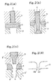
- the stripper (3) or the stripper (3') mechanically stops just before the green sheet (11), and then only the punch (4) or the punch (5) is moved to machine the green sheet.
- a method for producing a nozzle wherein said green sheet is prepared by using a ceramic powder having an average particle diameter of 0.2 ⁇ m - 1.0 ⁇ m.
- liquid injection device having a nozzle of the first or second aspect of the invention.
- a tip part of a nozzle 12 for a liquid injection device of the present invention forms projected parts 12a, 12b, and an internal surface the projected part is tapered toward an injection port to be narrower.
- a nozzle of the present invention has an inner diameter d 1 of 25 ⁇ m - 300 ⁇ m, a thickness t 1 of a green sheet of 50 ⁇ m - 200 ⁇ m, and an aspect ratio of the thickness to the inner diameter (t 1 /d 1 : hereinbelow referred to simply as aspect ratio) of 0.5 - 2.5.
- a method for producing a nozzle of the present invention includes the steps of: disposing a ceramic green sheet 11 to be used as a bottom part of a liquid injection device to which a nozzle is attached between a die 2 and a stripper 3 storing a punch 4 therein as shown in Fig. 2 (a), moving the punch 4 to form a hole forming a nozzle in the green sheet 11 as shown in Fig. 2(b), disposing the green sheet between a die 2' having a cavity having a reversed configuration of a projected part and a stripper 3' storing a punch 5 therein so that the punch 5 is inserted in the green sheet 11 in the direction opposite to the direction in which the punch 4 is inserted in the green sheet as shown in Fig. 2(c), moving the punch 5 to obtain a configuration of the nozzle, and baking the green sheet.
- a clearance between a side portion of the punch 5 and the point p of the die 2' is within the range from 2 to 5 times the maximum particle diameter of a ceramic powder forming the green sheet, that is, within the thickness range in which the green sheet shows an extreme decrease in strength. If vacuum absorption upon punching the green sheet can prevent refuse from adhering to the hole of the green sheet or from rising up to the upper surface of the green sheet. It is also effective in preventing the refuse from adhering to a tip part of the punch. A tapered shape of the die to be wider toward the direction of punching is more effective. A nozzle can be produced more precisely if the stripper 3 or the stripper 3' mechanically stops just before the green sheet 11, and then only the punch 4 or the punch 5 is moved to machine the green sheet in the method.
- a communicating portion 12d of the nozzle hole is tapered to be narrower toward the projected parts.
- the projected parts 12a, 12b are edges each having a radius of curvature of 10 ⁇ m or less.
- the tapering is about 1/30 - 1/10.
- an evading portion 12f locating outside the projected part having r of the nozzle hole, from the projected part 12b to an evading curved portion 12e via an upper-end liquid guide portion 12c having r of the nozzle hole preferably have a suitable radius of curvature R so as to prevent ceramics from cracking due to stress upon being baked.
- R is within the range from t 1 /3 to t 1 /10.
- a tip part of the projected part preferably has a length corresponding to a radius of curvature R of 12 C arranged to reduce a resistance in flow path.
- a cross section of the nozzle portion may be any of circular, oval, square, and rectangular, it is preferably circular in view of workability and liquid injection efficiency.
- An injection device is generally unitarily baked to produce a nozzle having a projected part of the present invention by the use of a thus produced green sheet 11.
- An injection device to be unitarily baked is produced according to a method, for example, the one disclosed in paragraphs 0010 - 0013 of the specification for the Japanese Patent Application 9-335210.
- a ceramic material to be used for producing a green sheet employs a machining method by which a relatively high shearing force is applied when a nozzle having the aforementioned shape and size, a green sheet having a shearing stress of 2 - 10kgf/mm 2 can be suitably used.
- a suitable raw material for preparing a green sheet having such a shearing stress there can be suitably used a material, for example, zirconia, alumina, silicon nitride, and silicon carbide.
- a method for producing a liquid injection device having a nozzle having a projected part of the present invention, where a green sheet produced in the aforementioned method, is hereinbelow described with reference to Fig. 4.
- a pump portion 21 is formed by stacking a nozzle plate 13 which is a nozzle portion 11 formed of a thin plate-like green sheet prepared with a ceramic having an average diameter of about 0.2 ⁇ m - 1.0 ⁇ m and which is provided with a nozzle hole 12 formed in the aforementioned manner; a spacer plate 25 which is formed of a ceramic green sheet and provided with a window portion 28, and a sealing plate 23 which covers the window portion 28 by being superposed on one side of the spensor plate 25 and is provided with a liquid inflow port 16.
- a nozzle plate 13 which is a nozzle portion 11 formed of a thin plate-like green sheet prepared with a ceramic having an average diameter of about 0.2 ⁇ m - 1.0 ⁇ m and which is provided with a nozzle hole 12 formed in the aforementioned manner
- a spacer plate 25 which is formed of a ceramic green sheet and provided with a window portion 28, and a sealing plate 23 which covers the window portion 28 by being superposed on one side of the spensor plate
- a piezoelectric/electrostrictive element 22 having a lower element 31, a piezoelectric/electrostrictive layer 32, and an upper element 33 is disposed on the outer surface of sealing plate 23 of thus obtained structure.
- a piezoelectric/electrostrictive layer 32 is deformed, and the cavity (liquid pressure chamber) 15 formed with the window portion 28 being covered decreases in capacity when an electric field is generated between the upper electrode 33 and the lower electrode 31, and thereby liquid filling a cavity 15 is injected from the nozzle hole 12 communicating.
- a liquid injected device may be made of zirconia ceramics as a raw material.
- a device after being baked is excellent in chemical resistance, thermal resistance, and tenacity. Therefore, even if a solvent for liquid to be dried uses a liquid used for preparing a precursor of a ceramic material, such as acetone type, hydrochloric acid type, or the like, or even if liquid for combustion is kerosine or gasolin, it is possible to use it.
- Ethyl alcohol solution of zirconium chloride is intermittently sprayed inside a quartz furnace 43 having an external heater 42 by an electromagnetic shutter 41 to give liquid drops.
- the liquid drops in the furnace 43 were dried and thermally decomposed to obtain a zirconia ceramic powder A.
- the obtained zirconia ceramic powder A had an average particle diameter of 20 ⁇ m and was so uniform that the particle-size distribution was within ⁇ 10% of the average particle diameter.
- liquid injected at a tip part of the nozzle does not substantially adhere as a solid substance even if the nozzle is mounted in a device to which air is constantly applied in a direction perpendicular to the direction where liquid is injected, for example a drying device.
- a nozzle of the present invention by using a nozzle of the present invention, there is exhibited an excellent effect of avoiding a hindrance that smooth operation for discharging liquid is hindered due to sticking of dried injection liquid to a tip part of the nozzle or that desired operation is made impossible due to complete clogging of the nozzle, or the like.
- a liquid injection device having a nozzle with a projected part of the present invention exhibits an excellent effect of being capable of long continuous driving because it does not need to stop driving so as to remove deposites while the device is used since the device is substantially free from adhesion of injected liquid which is solidified in a tip part of a nozzle.
Landscapes
- Engineering & Computer Science (AREA)
- Structural Engineering (AREA)
- Chemical & Material Sciences (AREA)
- Ceramic Engineering (AREA)
- Mechanical Engineering (AREA)
- Devices For Post-Treatments, Processing, Supply, Discharge, And Other Processes (AREA)
- Particle Formation And Scattering Control In Inkjet Printers (AREA)
- Nozzles (AREA)
Applications Claiming Priority (3)
| Application Number | Priority Date | Filing Date | Title |
|---|---|---|---|
| JP19088698 | 1998-07-06 | ||
| JP19088698A JP3466480B2 (ja) | 1998-07-06 | 1998-07-06 | 液体吐出装置用ノズル及びその製造方法 |
| PCT/JP1999/003600 WO2000001492A1 (fr) | 1998-07-06 | 1999-07-02 | Projecteur a cristaux liquides |
Publications (1)
| Publication Number | Publication Date |
|---|---|
| EP1010467A1 true EP1010467A1 (de) | 2000-06-21 |
Family
ID=16265388
Family Applications (1)
| Application Number | Title | Priority Date | Filing Date |
|---|---|---|---|
| EP99926919A Withdrawn EP1010467A1 (de) | 1998-07-06 | 1999-07-02 | Einspritzdüse für flüssigkeiten und deren herstellungsverfahren |
Country Status (4)
| Country | Link |
|---|---|
| US (2) | US6256884B1 (de) |
| EP (1) | EP1010467A1 (de) |
| JP (1) | JP3466480B2 (de) |
| WO (1) | WO2000001492A1 (de) |
Cited By (1)
| Publication number | Priority date | Publication date | Assignee | Title |
|---|---|---|---|---|
| EP2801457A1 (de) * | 2013-05-07 | 2014-11-12 | Sistemas Tecnicos de Castellon, S.L. | Verfahren zur Herstellung geformter Keramikfabrikate |
Families Citing this family (11)
| Publication number | Priority date | Publication date | Assignee | Title |
|---|---|---|---|---|
| FR2807467B1 (fr) | 2000-04-05 | 2002-06-07 | Peugeot Citroen Automobiles Sa | Moteur a combustion interne pour vehicule automobile |
| US8210455B2 (en) * | 2001-04-06 | 2012-07-03 | Brian L. Verrilli | Deep drawn nozzle for precision liquid dispensing |
| US6722581B2 (en) * | 2001-10-24 | 2004-04-20 | General Electric Company | Synthetic jet actuators |
| US6764023B2 (en) * | 2002-10-09 | 2004-07-20 | Industrial Technology Research Institute | Bi-direction pumping droplet mist ejection apparatus |
| US7712680B2 (en) * | 2006-01-30 | 2010-05-11 | Sono-Tek Corporation | Ultrasonic atomizing nozzle and method |
| US9272297B2 (en) * | 2008-03-04 | 2016-03-01 | Sono-Tek Corporation | Ultrasonic atomizing nozzle methods for the food industry |
| WO2009155245A1 (en) * | 2008-06-17 | 2009-12-23 | Davicon Corporation | Liquid dispensing apparatus using a passive liquid metering method |
| US8662889B2 (en) * | 2008-08-27 | 2014-03-04 | Georgetown University | Arch bars for use in maxillofacial surgery and orthodontics |
| JP5903769B2 (ja) * | 2011-03-29 | 2016-04-13 | セイコーエプソン株式会社 | 液体噴射ヘッドおよび液体噴射装置 |
| DE102012209326A1 (de) * | 2012-06-01 | 2013-12-05 | Robert Bosch Gmbh | Brennstoffeinspritzventil |
| DE102013225948A1 (de) * | 2013-12-13 | 2015-06-18 | Continental Automotive Gmbh | Düsenkopf und Fluid-Einspritzventil |
Family Cites Families (14)
| Publication number | Priority date | Publication date | Assignee | Title |
|---|---|---|---|---|
| US1802961A (en) * | 1928-04-11 | 1931-04-28 | Taylor James Hall | Method of making nozzles |
| US2065915A (en) * | 1934-11-08 | 1936-12-29 | Gen Fire Extinguisher Co | Method for forming branch nozzles on pipes |
| SE350416B (de) * | 1971-08-24 | 1972-10-30 | Stora Kopparbergs Bergslags Ab | |
| US3947940A (en) * | 1973-01-30 | 1976-04-06 | Augustine Frank B | Method for making cone spray nozzle |
| US3978705A (en) * | 1975-03-14 | 1976-09-07 | Cotton Incorporated | Method and apparatus for the manufacture of a thin sheet orifice plate |
| US4010298A (en) * | 1975-12-03 | 1977-03-01 | Angle William M | Underground irrigation devices and methods of making and using the same |
| JPS5549162A (en) * | 1978-10-03 | 1980-04-09 | Ikeuchi:Kk | Mist producting device |
| JPS648953A (en) | 1987-06-30 | 1989-01-12 | Yokogawa Medical Syst | Mti pulse doppler apparatus |
| JPS648953U (de) * | 1987-07-02 | 1989-01-18 | ||
| IL100224A (en) * | 1990-12-04 | 1994-10-21 | Dmw Tech Ltd | Spray nozzle |
| JP2500225B2 (ja) * | 1993-01-26 | 1996-05-29 | テーデーエフ株式会社 | ピアシング成形方法および装置 |
| JPH07205095A (ja) * | 1994-01-27 | 1995-08-08 | Hitachi Ltd | セラミックグリーンシートの穴抜き装置 |
| JPH07227651A (ja) * | 1994-02-22 | 1995-08-29 | Unitika Ltd | 金属細線製造用ノズル |
| DE19541174C2 (de) * | 1995-11-04 | 1998-11-26 | Spraying Systems Deutschland G | Hochleistungsstrahldüse |
-
1998
- 1998-07-06 JP JP19088698A patent/JP3466480B2/ja not_active Expired - Fee Related
-
1999
- 1999-07-02 EP EP99926919A patent/EP1010467A1/de not_active Withdrawn
- 1999-07-02 WO PCT/JP1999/003600 patent/WO2000001492A1/ja not_active Application Discontinuation
-
2000
- 2000-03-01 US US09/516,106 patent/US6256884B1/en not_active Expired - Fee Related
-
2001
- 2001-05-22 US US09/863,107 patent/US6585175B2/en not_active Expired - Fee Related
Non-Patent Citations (1)
| Title |
|---|
| See references of WO0001492A1 * |
Cited By (1)
| Publication number | Priority date | Publication date | Assignee | Title |
|---|---|---|---|---|
| EP2801457A1 (de) * | 2013-05-07 | 2014-11-12 | Sistemas Tecnicos de Castellon, S.L. | Verfahren zur Herstellung geformter Keramikfabrikate |
Also Published As
| Publication number | Publication date |
|---|---|
| JP2000015819A (ja) | 2000-01-18 |
| JP3466480B2 (ja) | 2003-11-10 |
| US6585175B2 (en) | 2003-07-01 |
| US20010022024A1 (en) | 2001-09-20 |
| US6256884B1 (en) | 2001-07-10 |
| WO2000001492A1 (fr) | 2000-01-13 |
Similar Documents
| Publication | Publication Date | Title |
|---|---|---|
| EP1010467A1 (de) | Einspritzdüse für flüssigkeiten und deren herstellungsverfahren | |
| KR100828265B1 (ko) | 세라믹 구조체, 세라믹 구조체의 제조 장치 및 세라믹구조체의 제조 방법 | |
| JP4222588B2 (ja) | ハニカムフィルター及びその製造方法 | |
| JP5524696B2 (ja) | 目封止ハニカム構造体の製造方法 | |
| KR100715406B1 (ko) | 압전 구조체, 액체 토출 헤드 및 그 제조 방법 | |
| US20080128082A1 (en) | Method for Manufacturing Plugged Honeycomb Structure | |
| EP1148561A3 (de) | Piezoelektrische/elektrostriktive Film-Bauelemente sowie deren Herstellungsverfahren | |
| WO2009052805A2 (de) | Düsen-, filter- oder/und positionierelement | |
| EP1672712B1 (de) | Verfahren zur Herstellung keramischer Dickschichtelement-Arrays mit feiner Strukturgrösse, hochpräziser Definition und/oder hohen Aspektverhältnissen | |
| US6378995B1 (en) | Manufacturing method of nozzle plate using silicon process and ink jet printer head applying the nozzle plate | |
| EP0882505B1 (de) | Verfahren zur Herstellung eines Wabenkörper-Katalysators | |
| JP4748730B2 (ja) | セラミックスフィルタ及びその端面シール方法 | |
| CN1822897A (zh) | 微型反应器 | |
| JP2002036217A (ja) | ハニカム成形体及びその製造方法 | |
| WO2003051635A2 (en) | Low voltage ink jet printing module | |
| JP6810075B2 (ja) | 焼成治具 | |
| JPH034582A (ja) | セラミック基板 | |
| KR101464825B1 (ko) | 도포 장치 | |
| CN109081302B (zh) | 一种微通道加工方法、微通道 | |
| JP3254992B2 (ja) | インクジェットヘッドの製造方法 | |
| JPH06220658A (ja) | シリコンの噴射板の製法及びシリコン板 | |
| JP5947883B2 (ja) | 押出成形用金型、押出成形用金型の製造方法、押出成形装置及びハニカム構造体の製造方法 | |
| US7914721B2 (en) | Process for producing a ceramic material | |
| CN1308146C (zh) | 液体喷出头及其制造方法 | |
| JPH0550606A (ja) | インクジエツトプリンタヘツド用圧電素子の製造方法 |
Legal Events
| Date | Code | Title | Description |
|---|---|---|---|
| PUAI | Public reference made under article 153(3) epc to a published international application that has entered the european phase |
Free format text: ORIGINAL CODE: 0009012 |
|
| 17P | Request for examination filed |
Effective date: 20000327 |
|
| AK | Designated contracting states |
Kind code of ref document: A1 Designated state(s): AT BE CH CY DE DK ES FI FR GB GR IE IT LI LU MC NL PT SE |
|
| STAA | Information on the status of an ep patent application or granted ep patent |
Free format text: STATUS: THE APPLICATION HAS BEEN WITHDRAWN |
|
| 18W | Application withdrawn |
Effective date: 20040312 |
|
| RBV | Designated contracting states (corrected) |
Designated state(s): DE FR GB IT |