EP1010189B1 - Schalter mit magnetisch gekoppeltem anker - Google Patents
Schalter mit magnetisch gekoppeltem anker Download PDFInfo
- Publication number
- EP1010189B1 EP1010189B1 EP98945854A EP98945854A EP1010189B1 EP 1010189 B1 EP1010189 B1 EP 1010189B1 EP 98945854 A EP98945854 A EP 98945854A EP 98945854 A EP98945854 A EP 98945854A EP 1010189 B1 EP1010189 B1 EP 1010189B1
- Authority
- EP
- European Patent Office
- Prior art keywords
- armature
- switch
- membrane
- carrier
- coupler
- Prior art date
- Legal status (The legal status is an assumption and is not a legal conclusion. Google has not performed a legal analysis and makes no representation as to the accuracy of the status listed.)
- Expired - Lifetime
Links
- 230000005291 magnetic effect Effects 0.000 claims description 30
- 230000033001 locomotion Effects 0.000 claims description 13
- 239000000696 magnetic material Substances 0.000 claims description 11
- 239000012528 membrane Substances 0.000 description 80
- 125000006850 spacer group Chemical group 0.000 description 28
- 239000000758 substrate Substances 0.000 description 27
- 239000000463 material Substances 0.000 description 10
- 230000007246 mechanism Effects 0.000 description 7
- 230000008901 benefit Effects 0.000 description 6
- 229920003023 plastic Polymers 0.000 description 6
- 230000036316 preload Effects 0.000 description 6
- 230000035807 sensation Effects 0.000 description 5
- BQCADISMDOOEFD-UHFFFAOYSA-N Silver Chemical compound [Ag] BQCADISMDOOEFD-UHFFFAOYSA-N 0.000 description 4
- 230000006870 function Effects 0.000 description 4
- 229910052709 silver Inorganic materials 0.000 description 4
- 239000004332 silver Substances 0.000 description 4
- 238000010276 construction Methods 0.000 description 3
- 239000000428 dust Substances 0.000 description 3
- 210000000006 pectoral fin Anatomy 0.000 description 3
- RYGMFSIKBFXOCR-UHFFFAOYSA-N Copper Chemical compound [Cu] RYGMFSIKBFXOCR-UHFFFAOYSA-N 0.000 description 2
- 229910000831 Steel Inorganic materials 0.000 description 2
- 230000005540 biological transmission Effects 0.000 description 2
- 229910052802 copper Inorganic materials 0.000 description 2
- 239000010949 copper Substances 0.000 description 2
- 230000008878 coupling Effects 0.000 description 2
- 238000010168 coupling process Methods 0.000 description 2
- 238000005859 coupling reaction Methods 0.000 description 2
- 238000012217 deletion Methods 0.000 description 2
- 230000037430 deletion Effects 0.000 description 2
- 230000000881 depressing effect Effects 0.000 description 2
- 230000000994 depressogenic effect Effects 0.000 description 2
- 230000005294 ferromagnetic effect Effects 0.000 description 2
- 239000007788 liquid Substances 0.000 description 2
- 229910052751 metal Inorganic materials 0.000 description 2
- 239000002184 metal Substances 0.000 description 2
- 229920000728 polyester Polymers 0.000 description 2
- 239000011435 rock Substances 0.000 description 2
- 230000035939 shock Effects 0.000 description 2
- 238000005476 soldering Methods 0.000 description 2
- 239000010959 steel Substances 0.000 description 2
- 230000009471 action Effects 0.000 description 1
- 230000004075 alteration Effects 0.000 description 1
- 230000008859 change Effects 0.000 description 1
- 239000012141 concentrate Substances 0.000 description 1
- 239000004020 conductor Substances 0.000 description 1
- 238000006073 displacement reaction Methods 0.000 description 1
- 230000000694 effects Effects 0.000 description 1
- 238000004049 embossing Methods 0.000 description 1
- 238000005530 etching Methods 0.000 description 1
- 239000003302 ferromagnetic material Substances 0.000 description 1
- 229920002457 flexible plastic Polymers 0.000 description 1
- 238000007667 floating Methods 0.000 description 1
- 238000005304 joining Methods 0.000 description 1
- 238000004519 manufacturing process Methods 0.000 description 1
- 230000004048 modification Effects 0.000 description 1
- 238000012986 modification Methods 0.000 description 1
- 230000003647 oxidation Effects 0.000 description 1
- 238000007254 oxidation reaction Methods 0.000 description 1
- 230000001012 protector Effects 0.000 description 1
- 230000000284 resting effect Effects 0.000 description 1
- 230000000717 retained effect Effects 0.000 description 1
- 229910052703 rhodium Inorganic materials 0.000 description 1
- 239000010948 rhodium Substances 0.000 description 1
- MHOVAHRLVXNVSD-UHFFFAOYSA-N rhodium atom Chemical compound [Rh] MHOVAHRLVXNVSD-UHFFFAOYSA-N 0.000 description 1
- 238000007650 screen-printing Methods 0.000 description 1
- 238000007789 sealing Methods 0.000 description 1
Images


Classifications
-
- G—PHYSICS
- G01—MEASURING; TESTING
- G01D—MEASURING NOT SPECIALLY ADAPTED FOR A SPECIFIC VARIABLE; ARRANGEMENTS FOR MEASURING TWO OR MORE VARIABLES NOT COVERED IN A SINGLE OTHER SUBCLASS; TARIFF METERING APPARATUS; MEASURING OR TESTING NOT OTHERWISE PROVIDED FOR
- G01D5/00—Mechanical means for transferring the output of a sensing member; Means for converting the output of a sensing member to another variable where the form or nature of the sensing member does not constrain the means for converting; Transducers not specially adapted for a specific variable
- G01D5/12—Mechanical means for transferring the output of a sensing member; Means for converting the output of a sensing member to another variable where the form or nature of the sensing member does not constrain the means for converting; Transducers not specially adapted for a specific variable using electric or magnetic means
- G01D5/14—Mechanical means for transferring the output of a sensing member; Means for converting the output of a sensing member to another variable where the form or nature of the sensing member does not constrain the means for converting; Transducers not specially adapted for a specific variable using electric or magnetic means influencing the magnitude of a current or voltage
- G01D5/16—Mechanical means for transferring the output of a sensing member; Means for converting the output of a sensing member to another variable where the form or nature of the sensing member does not constrain the means for converting; Transducers not specially adapted for a specific variable using electric or magnetic means influencing the magnitude of a current or voltage by varying resistance
- G01D5/165—Mechanical means for transferring the output of a sensing member; Means for converting the output of a sensing member to another variable where the form or nature of the sensing member does not constrain the means for converting; Transducers not specially adapted for a specific variable using electric or magnetic means influencing the magnitude of a current or voltage by varying resistance by relative movement of a point of contact or actuation and a resistive track
-
- G—PHYSICS
- G01—MEASURING; TESTING
- G01D—MEASURING NOT SPECIALLY ADAPTED FOR A SPECIFIC VARIABLE; ARRANGEMENTS FOR MEASURING TWO OR MORE VARIABLES NOT COVERED IN A SINGLE OTHER SUBCLASS; TARIFF METERING APPARATUS; MEASURING OR TESTING NOT OTHERWISE PROVIDED FOR
- G01D5/00—Mechanical means for transferring the output of a sensing member; Means for converting the output of a sensing member to another variable where the form or nature of the sensing member does not constrain the means for converting; Transducers not specially adapted for a specific variable
- G01D5/02—Mechanical means for transferring the output of a sensing member; Means for converting the output of a sensing member to another variable where the form or nature of the sensing member does not constrain the means for converting; Transducers not specially adapted for a specific variable using mechanical means
- G01D5/06—Mechanical means for transferring the output of a sensing member; Means for converting the output of a sensing member to another variable where the form or nature of the sensing member does not constrain the means for converting; Transducers not specially adapted for a specific variable using mechanical means acting through a wall or enclosure, e.g. by bellows, by magnetic coupling
-
- H—ELECTRICITY
- H01—ELECTRIC ELEMENTS
- H01H—ELECTRIC SWITCHES; RELAYS; SELECTORS; EMERGENCY PROTECTIVE DEVICES
- H01H36/00—Switches actuated by change of magnetic field or of electric field, e.g. by change of relative position of magnet and switch, by shielding
-
- H—ELECTRICITY
- H01—ELECTRIC ELEMENTS
- H01H—ELECTRIC SWITCHES; RELAYS; SELECTORS; EMERGENCY PROTECTIVE DEVICES
- H01H5/00—Snap-action arrangements, i.e. in which during a single opening operation or a single closing operation energy is first stored and then released to produce or assist the contact movement
- H01H5/02—Energy stored by the attraction or repulsion of magnetic parts
-
- H—ELECTRICITY
- H01—ELECTRIC ELEMENTS
- H01H—ELECTRIC SWITCHES; RELAYS; SELECTORS; EMERGENCY PROTECTIVE DEVICES
- H01H1/00—Contacts
- H01H1/12—Contacts characterised by the manner in which co-operating contacts engage
- H01H1/14—Contacts characterised by the manner in which co-operating contacts engage by abutting
- H01H1/16—Contacts characterised by the manner in which co-operating contacts engage by abutting by rolling; by wrapping; Roller or ball contacts
-
- H—ELECTRICITY
- H01—ELECTRIC ELEMENTS
- H01H—ELECTRIC SWITCHES; RELAYS; SELECTORS; EMERGENCY PROTECTIVE DEVICES
- H01H3/00—Mechanisms for operating contacts
- H01H3/32—Driving mechanisms, i.e. for transmitting driving force to the contacts
- H01H3/50—Driving mechanisms, i.e. for transmitting driving force to the contacts with indexing or locating means, e.g. indexing by ball and spring
- H01H2003/506—Driving mechanisms, i.e. for transmitting driving force to the contacts with indexing or locating means, e.g. indexing by ball and spring making use of permanent magnets
-
- H—ELECTRICITY
- H01—ELECTRIC ELEMENTS
- H01H—ELECTRIC SWITCHES; RELAYS; SELECTORS; EMERGENCY PROTECTIVE DEVICES
- H01H2215/00—Tactile feedback
- H01H2215/034—Separate snap action
- H01H2215/042—Permanent magnets
-
- H—ELECTRICITY
- H01—ELECTRIC ELEMENTS
- H01H—ELECTRIC SWITCHES; RELAYS; SELECTORS; EMERGENCY PROTECTIVE DEVICES
- H01H2219/00—Legends
- H01H2219/002—Legends replaceable; adaptable
- H01H2219/004—Magnet
-
- H—ELECTRICITY
- H01—ELECTRIC ELEMENTS
- H01H—ELECTRIC SWITCHES; RELAYS; SELECTORS; EMERGENCY PROTECTIVE DEVICES
- H01H25/00—Switches with compound movement of handle or other operating part
-
- H—ELECTRICITY
- H01—ELECTRIC ELEMENTS
- H01H—ELECTRIC SWITCHES; RELAYS; SELECTORS; EMERGENCY PROTECTIVE DEVICES
- H01H25/00—Switches with compound movement of handle or other operating part
- H01H25/06—Operating part movable both angularly and rectilinearly, the rectilinear movement being along the axis of angular movement
- H01H25/065—Operating part movable both angularly and rectilinearly, the rectilinear movement being along the axis of angular movement using separate operating parts, e.g. a push button surrounded by a rotating knob
-
- H—ELECTRICITY
- H01—ELECTRIC ELEMENTS
- H01H—ELECTRIC SWITCHES; RELAYS; SELECTORS; EMERGENCY PROTECTIVE DEVICES
- H01H9/00—Details of switching devices, not covered by groups H01H1/00 - H01H7/00
- H01H9/02—Bases, casings, or covers
- H01H9/04—Dustproof, splashproof, drip-proof, waterproof, or flameproof casings
Definitions
- Membrane switches are well known for providing electrical switching functions in a reliable, compact package.
- Membrane switches typically have a flexible plastic membrane layer normally separated from a substrate by a nonconductive spacer.
- Openings in the spacer permit a user to push the membrane through the spacer, bringing facing electrical contacts on the internal surfaces of the membrane and substrate into contact with one another, thereby closing a switch.
- the natural resilience of the membrane returns the membrane to its spaced position upon removal of the actuating force.
- the membrane switch is often a flat panel with graphical elements indicating where to press but having no protruding actuating member.
- membrane switches provide perfectly adequate electrical switching, manufacturers have found that users expecting to find a rotary switch or a slide switch or a pushbutton switch for a certain function don't take kindly to having the familiar switch replaced with a flat panel membrane switch.
- the present invention is directed to an electrical switch as described in Claim 1.
- Preferred features are described in Claims 2 to 4 inclusive.
- Document EP 0 746 006 discloses a device according to the preamble of claim 1.
- the present invention concerns incorporating rotary, pushbutton and slide switches or potentiometers into a flat panel switch. This combines the benefits of membrane switches with the look and feel users are accustomed to with traditional switches.
- the rotary and slide switches have a knob mounted on a carrier sheet for rotary, linear or complex motion.
- the knob carries a magnet for movement therewith adjacent the external surface of the carrier.
- Electrodes including at least one pair of spaced switch contacts are formed on the underside of the carrier.
- An armature is made of electrically conductive and magnetic material. By magnetic material it is meant that the material is affected by a magnet. The magnet holds the armature up against the underside of the carrier and, accordingly, against the electrodes. Movement of the knob drags the armature into and out of shorting relation with the switch contacts.
- the armature can be a flat, disc-shaped element. Alternately, it can be cylindrical or spherical.
- armature configurations include a flipper having two or more stable positions wherein different sets of contacts are shorted.
- a detent gear can be used to provide tactile feedback of movement into and out of switch closure.
- some sort of substrate, ball retainer or blister pack is used to protect and seal the electrodes and armature.
- a spacer with an opening in which the armature is disposed permits movement of the armature.
- the rotary and slide switches of the present invention offer numerous advantages.
- the switches can be integrated into flat, continuous switch panels. Sealing integrity of the flat panels can be maintained since the switch contacts are located inside the switch. Seals rings can be readily employed to seal against dirt, dust and liquids.
- the knobs can be adhesively bonded to the front surface of a switch panel without the need to penetrate the continuously sealed surface.
- Off-center magnets can be employed to cause the armature to rotate during actuation thereby extending life.
- a virtually wear- proof magnetic detent can be added.
- a magnetic pre-load can be added in applications where the switch is subject to shock and vibration in use.
- Motor drives and magnetic clutches can be provided for applications such as washer timer controls.
- Integral membrane switch panels can be provided with pushbutton membrane switches, slide switches and rotary switches, or potentiometers, all integrated into one continuous panel.
- Low cost silver conductors can be used as switch contacts.
- Etched copper contacts can be provided for high current applications. Tactile feedback can be provided.
- the switches can be made as discrete, stand-alone components.
- High temperature membrane materials can be employed for high temperature applications, including high temperature processing such as wave soldering.
- Low cost polyester membranes can be employed as a carrier sheet or a printed circuit board could
- the pushbutton switch has a layer of magnetic material between a spacer and a membrane.
- An armature in the spacer opening is pivotable between a normal position, in which it is spaced from electrodes on the substrate, and a closed position, in which it shorts the electrodes.
- the armature is held in its normal position by the magnetic attraction between the magnetic layer and the armature.
- When a user depresses the membrane the armature suddenly snaps free of the magnetic layer and closes against the electrodes, providing a switch closure and tactile feedback thereof. Removal of the closing pressure allows the magnetic layer to retract the armature and reopen the switch.
- a fulcrum built into one end of the armature assists the pivoting motion of the armature.
- a rocking armature is disposed under a membrane in an opening of a spacer and on top of a substrate. Electrical contacts on the upper surface of the substrate are bridged by the armature which rocks back and forth in the nature of a seesaw.
- the armature has a central fulcrum engaging a common contact. The ends of the armature alternately make and break contact with outer contacts, as controlled by a user depressing the membrane. Magnets located beneath the surface of the substrate retain the armature in one position or the other.
- a further alternate pushbutton switch configuration combines a pushbutton switch with one of a rotary switch, slide switch or potentiometer.
- a complete membrane switch is located underneath a flexible carrier sheet having the rotary or slide switch contacts thereon.
- the membrane switch comprises a membrane, spacer and substrate, with facing contacts on the inner surfaces of the membrane and substrate.
- a pushbutton extends through the knob of the rotary switch and actuates the underlying membrane switch.
- Figs. 1 and 2 illustrate a rotary switch not according to the present invention.
- the switch shown generally at 10 includes a substrate layer 12, a nonconductive spacer 14 and a carrier in the form of a membrane layer 16.
- the internal surface of the membrane carries a set of electrodes which define the spaced contacts of at least one electrical switch.
- the electrodes are conventionally formed either by screen printing or etching in copper. These contacts are configured in such a manner as to allow at least two contacts to be shorted together by a metallic armature 18.
- the armature is made of an electrically conductive magnetic material.
- One example would be soft steel plated with silver.
- the silver is added to enhance electrical conductivity and resist oxidation. A harder material such as rhodium could be added to improve wear resistance.
- An opening 20 in the spacer receives the armature 18.
- the armature is a flat, circular disc.
- An actuating knob 22 is mounted for rotation on the switch by a bolt.
- the bolt has a head 23 and a shaft 24 extending through the membrane, spacer opening and substrate.
- a sleeve 25 surrounds the shaft above the membrane.
- a nut 26 holds the bolt in place.
- a seal ring 28 prevents entry of dirt, dust or moisture into the spacer opening.
- the nut 26 is tightened on shaft 24 to compress the seal ring 28 and sleeve 25 slightly.
- the actuating knob has a central bore that is large enough to permit rotation of the knob on the sleeve.
- the bolt head 23 prevents the knob from coming off the switch.
- the nut is shown as a separate part but alternately its function could be served by a drilled and tapped enlarged portion of the substrate.
- the sleeve 25 could be adhesively bonded to the top of the membrane. In that case the nut would not be needed and the shaft of the bolt would stop short of the membrane.
- the knob 22 carries a coupler 30 in its underside.
- the coupler is a magnet which may be molded or otherwise entrapped in the knob. Where magnetic interference with other electronic components is a concern, the coupler may be shielded as needed.
- the coupler 30 forces the armature 18 against the internal surface of the membrane by means of the magnetic field originating from the coupler.
- the coupler functions both to create the switch contact pressure as well as to drag the armature 18 from one contact to another when a user rotates the knob 22.
- knob could be either in or out of contact with the external surface of the membrane.
- magnet may or may not contact the membrane's external surface.
- Contact, or lack or it, between the knob or magnet and the membrane is not critical so long as the magnet is close enough to the armature to maintain coupling of the magnet and armature, i.e., the armature always moves with the magnet.
- the switch Operation of the switch is as follows.
- the coupler 30 rotates with the knob.
- the armature rotates with the knob.
- the armature moves into shorting contact with the contacts on the membrane, thereby closing the switch. Further rotation will move the armature out of contact with one or both electrodes to open the switch.
- more than one set of switch contacts may be placed under the rotational area of a single knob, providing a plurality of switches under one knob.
- the space traversed by the armature as it rotates with the coupler defines a ring. Toward the inside diameter of that ring may be a circular common contact.
- Toward the outside diameter of the ring may be a plurality of exterior electrodes terminating at a point inside the ring but spaced from each other and the common contact.
- the armature is always in contact with the common contact but moves into and out of contact with the exterior contacts.
- the circular common contact could be a split ring or the like. Numerous variations are possible.
- Fig. 3 illustrates a digital gear 32 which may optionally be incorporated in the rotary switch 10.
- the gear has a hub 34 with a plurality of cogs 36. Four cogs are shown but any number could be included as space permits, the dashed, diagonal lines in Fig. 3 indicating possible additional cog locations.
- the gear would be located on the external surface of the membrane 16, with the hub 34 surrounding the shaft 24 and the sleeve 25 sitting on top of the gear. The sleeve in this case would be shortened by the thickness of the gear 32.
- the underside of the knob 22 would also be cut out to accommodate the gear.
- the gear does not rotate with the knob but instead remains in a fixed position since it is compressed between the sleeve 25 and membrane 16.
- the cogs extend to the inside diameter of the circle described by the rotation of the coupler 30.
- the gear is made of magnetic material so that as the knob rotates the coupler into alignment with a cog the magnetic attraction between the coupler and cog creates a tactile sensation to the user.
- a second magnet carried by the knob could be used in cooperation with the digital gear to provide tactile feedback.
- Figs. 4 and 5 illustrate a slide switch 38. It has a substrate 40, a spacer 42 with an opening 44, and a carrier in the form of a membrane 46, all similar to the rotary switch 10.
- the opening 44 is an elongated rectangle.
- the internal surface of the carrier or membrane 46 has electrodes or traces 48A, 48B and 48C formed thereon. Electrode 48A is a common electrode while the ends of 48B and 48C are spaced apart as shown. It will be understood that this electrode arrangement is for purposes of illustration only and many variations are possible.
- a plastic housing 50 is mounted on the external surface of the membrane.
- the housing is generally a rectangular box with an elongated slot in the top which receives an actuator or knob 52.
- the actuator carries a coupler 54 which, in a preferred embodiment, is a magnet.
- An armature 56 is disposed in the opening 44.
- the armature may have the same disc-shape as in the rotary switch. Operation of the switch is similar to that of the rotary switch except the motion of the actuator 52 is linear instead of circular.
- the actuator carries the coupler 54 back and forth. Magnetic attraction between the coupler and armature causes the armature to move in conjunction with the coupler, connecting either trace 48B or 48C to trace 48A.
- the slide switch could also have a digital gear for providing a detent as in the rotary switch.
- the coupler magnet is placed off center relative to the armature. This is done intentionally to cause the armature to rotate as the actuator or knob is moved. This extends the life of the switch. While the offset coupler magnet is preferred, it is not necessary to arrange the magnet this way.
- the electrodes shown in the first two embodiments define a switch. They could also be arranged to form a potentiometer.
- a potentiometer can be constructed by replacing the switch contacts with a resistor element to form either a rotary or slide potentiometer.
- Figs. 6 and 7 illustrate an alternate embodiment of the slide switch. This embodiment is similar to switch 38 except for the armature.
- a cylindrical armature 58 is substituted for the flat, disc-shaped armature.
- the cylindrical armature exhibits no hysteresis, i.e., when the direction of the actuator is reversed, the armature 58 tracks directly with no hesitation.
- the cylindrical armature also minimizes friction between the armature and the conductive traces.
- Figs. 8-10 illustrate a further alternate embodiment of an armature.
- the armature is a pair of conductive balls 60.
- the balls have all the advantages of the cylindrical armature of Figs. 6 and 7 plus the following.
- the ball armature will track without either sliding or binding. This will allow for a complex actuating pattern such as the shifting pattern of a five-speed transmission.
- the ball armature configuration could be used in a rotary switch, a slide switch or something having a more complex actuating movement.
- Fig. 10 also illustrates that in its simplest form, the switch requires only a carrier with electrodes, a coupler and an armature.
- a spacer and substrate while probably desirable in most applications to protect the armature and electrodes, are not absolutely necessary.
- the carrier is shown as the flexible polyester membrane of a traditional membrane switch, it could be otherwise.
- a printed circuit board could serve as a carrier.
- the carrier need not be a thin, planar sheet. Although this may be the most practical configuration for many applications, any carrier arrangement that transmits enough of the magnetic field so that the armature always tracks with the coupler will suffice.
- Fig. 13 illustrates a variation of the switch having a twin-ball armature.
- this embodiment there are two coupler magnets 54A, 54B with oppositely arranged poles as shown.
- the magnet poles are directly above the balls. While two magnets are shown in the figure, these could be replaced by a single horseshoe magnet or a properly polarized bar magnet.
- the major force component of the magnetic field illustrated by field lines 86, directs the balls up against the switch contacts. This creates a higher contact force and reduces the tendency of the balls to float along a line drawn between the ball centers.
- Another possible variant of the ball armature is to add more balls, perhaps of different sizes, to achieve a multiple contact configuration.
- Figs. 14 and 15 illustrate a further variant of a slide switch 88. It has a substrate 90, a spacer 92 with an opening 94, and a carrier in the form of a membrane 96, all similar to the rotary switch 38.
- the opening 94 is an elongated rectangle.
- the internal surface of the carrier or membrane 96 has electrodes or traces 98A, 98B and 98C formed thereon. Electrode 98A is a common electrode while the ends of 98B and 98C are spaced apart as shown. It will be understood that this electrode arrangement is for purposes of illustration only and many variations are possible.
- a plastic housing 100 is mounted on the external surface of the membrane.
- the housing is generally a rectangular box with an elongated slot in the top which receives an actuator or knob 102.
- the actuator carries a coupler 104 which, in a preferred embodiment, is a magnet.
- An armature 106 is disposed in the opening 94.
- the armature is an angled piece of magnetic material having faces 108A, 108B joined at a vertex 109. The vertex is always in contact with trace 98A. Operation of the switch is similar to that of the Fig. 4 switch except the armature flips about its vertex rather than sliding.
- the actuator carries the coupler 104 back and forth. Magnetic attraction between the coupler and armature faces 108 causes the armature to flip back and forth, connecting either trace 98B or 98C to trace 98A.
- this armature 106 is the absence of friction between the armature and the switch contacts.
- This type of armature would be used in ultra-long life applications.
- the flipper armature concept could be extended to an armature with more than two faces and thus more than two stable positions to yield a multiple position switch.
- One example of this would be an inverted triangular pyramid or indeed a pyramid with any number of facets on its surface.
- Another extension would be to gang multiple flippers perpendicular to the direction of travel of the actuator. In this case multiple magnets would probably be required depending on the desired switch output.
- Figs. 11 and 12 illustrate a pushbutton switch 62.
- the switch 62 includes a substrate 64, a spacer 66 with an opening 68 therein, a layer 70 of a sheet magnet and a membrane 72.
- the membrane could be deleted, although it is preferred to have a membrane to seal against dust, dirt and liquids as well as to provide a surface for graphics to be printed.
- the membrane is normally embossed as at 74 to provide space for the actuating button 76 formed on armature 78. This space could also be made by placing a second spacer in between the top surface of magnetic layer 70 and the underside of the membrane 72.
- the armature 78 is located primarily within spacer opening 68. Its actuating button 76 protrudes through an aperture 80 in the magnetic layer 70.
- the lower surface of the armature has a fulcrum. In this case the fulcrum takes the form of a pair of extensions 82. The extensions are shown spaced from the electrode 84A but they could be in contact even when the switch is open.
- the armature is made of electrically conductive and magnetic material.
- the magnetic layer 70 holds the armature 78 up against the underside of the layer. Electrodes 84A, 84B are formed on the internal surface of the substrate.
- the user will press the actuating button 76.
- pre-travel is achieved when the membrane is first deformed.
- the armature abruptly breaks away from the magnetic sheet material thus providing a very crisp tactile sensation.
- the fulcrum extensions 82 will snap loose from magnetic layer 70 and engage electrode 84A. Thereafter the armature will pivot about the fulcrum and into contact with the electrode 84B. This shorts the electrodes and closes the switch.
- the magnetic attraction between layer 70 and the armature 78 will return the armature to the position of Fig. 12, thereby reopening the switch. Since the button 78 extends through aperture 80, the magnetic layer 70 moves very little, if at all during closure.
- Improved tactile feel can be achieved by placing a ferro-magnetic material on the top surface of the magnet sheet layer 70.
- This material has the effect of directing the magnetic field downwardly toward the armature. This material further enhances the tactile sensation by providing rigidity to the magnetic sheet material.
- a ferro-magnetic material is placed on the top surface of the magnet sheet layer 70.
- This material has the effect of directing the magnetic field downwardly toward the armature.
- This material further enhances the tactile sensation by providing rigidity to the magnetic sheet material.
- One example of such a material would be a thin soft steel sheet.
- the pushbutton switch as shown and described can be afforded a custom tactile feel by changing the position and size of the actuating button. Increased switch travel and/or overtravel can be achieved by adjusting the geometry and size of the armature. Ultra-short switch travel can be achieved by adjusting the position of the actuating button. Stand-alone, individual, discrete switches can be fabricated. The magnetic return force allows switches to be held in the actuated position for extended periods without becoming permanently actuated. Backlighting can be achieved by providing a hole in the armature. High temperature manufacturing processes including wave soldering can be used with high temperature materials. A printed circuit board could be used as a substrate. If an extra set of electrical contacts were located under the magnetic layer 70 (either on the layer 70 or on a membrane under the layer 70) a normally-closed switch could be incorporated in the switch of Figs. 11 and 12.
- FIG. 16 An alternate form of pushbutton switch is shown at 110 in Figs. 16 and 17.
- the switch 110 has a membrane 112 disposed on top of a spacer 114.
- a substrate 116 lies on the side of the spacer opposite the membrane.
- a plastic backing plate 118 is situated beneath the substrate 116.
- the internal surface of the substrate 116 has electrodes or traces 120A, 120B and 120C formed thereon which terminate at circular pads as shown in Fig. 16.
- Electrode 120B is a common electrode.
- An opening 122 in the spacer 114 receives a rocking armature 124.
- the armature 124 is made of magnetic material and has a pair of arms 126A, 126B extending in opposite directions from a central fulcrum 128.
- the armature pivots or rocks in the spacer opening 122 about the fulcrum 128 in seesaw fashion.
- the fulcrum rests on the pad of common electrode 120B.
- the arms 126A, 126B extend toward the pads of electrodes 120A and 120C.
- the arm 126B is shown in Fig. 17 in the actuated position wherein the arm is in contact with electrode 120C.
- a pair of magnets 130, 132 are embedded in the backing plate 118 beneath the substrate. The magnets retain the armature in an actuated position and provide a tactile sensation when the switch is operated. For example, in Fig.
- the arm 126B of armature 124 breaks contact with electrode 120C and opens the right switch. Then arm 126A makes contact with electrode 120A, closing the left switch formed by electrodes 120A and 120B.
- the pushbutton switch of Figs. 16 and 17 can also be tri-stable or multi-stable depending on the shape of the armature and the switch contact configuration. In a tri-stable configuration and beyond, the armature would take the shape of an inverted pyramid. A further alternate embodiment of this switch would involve deletion of one of the magnets 130 or 132. Such a switch could be termed mono-stable because the armature would always be in contact with the electrode above the remaining magnet except when a user is depressing another part of the membrane. When that pressure is released, the magnet would cause the armature to revert to its closed position. Thus, the switch would be normally-closed.
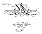
- Fig. 18 illustrates a rotary switch 134 having a pre-load mechanism.
- the coupler magnet is used to create a drag or pre-load on the actuating knob.
- the switch 134 includes a backing plate 136 and a membrane layer 138.
- the underside of the membrane carries a set of electrodes which define the electrical switch or potentiometer.
- a metallic armature 140 is situated in an opening 142 in the backing plate 136.
- an actuator plate 144 Located just above the membrane 138 is an actuator plate 144 which rotates with shaft 146 when a user turns an actuating knob 148.
- the shaft 146 is mounted for rotation in a plastic housing 150.
- a lock nut 151 retains the shaft in place.
- the lock nut also fastens a dial 153 which may be optionally placed on top of the housing 150.
- a ferromagnetic pre-load plate 152 rests between the underside of the housing 150 and the actuator plate 144.
- the plate 144 carries a coupler 154, which is a magnet similar to the coupler 30.
- the coupler not only moves the armature 140 to make and break the switch but also engages the pre-load plate 152.
- As the actuator plate rotates the friction between the pre-load plate and the coupler provides increased rotational torque.
- This arrangement could also be incorporated in a slide switch of the type shown in Figs. 4 and 5.
- Fig. 19 illustrates an alternate detent mechanism that could be incorporated in either a slide switch or a rotary switch.
- the particular embodiment shown is a slide switch.
- a floating detent plate 156 has a series of depressions or valleys 158 along one edge.
- the detent plate is constrained from longitudinal motion but is able to flex laterally to allow passage of a protrusion or bump 160 on the side edge of the actuator 162.
- the switch-actuating magnet 164 in the actuator provides the attractive force between the armature and actuator and between the detent plate 156 and the actuator. As the bump 160 slides into and out of the valleys 158 a distinct snap action is created which the user can easily feel, thereby indicating the making or breaking of the switch contacts.
- Fig. 20 illustrates a further alternate detent mechanism that could be incorporated in either a slide switch or a rotary switch.
- the particular embodiment shown is a rotary switch.
- the switch includes a carrier in the form of a membrane layer 166.
- the underside of the carrier has a set of electrodes which define the spaced contacts of at least one electrical switch or potentiometer.
- a twin-ball armature 168 rides on the underside of the carrier 166.
- the armature moves with a coupler magnet 170 which is mounted in a rotor 172.
- the rotor has an upstanding post 174 on which a knob 176 is mounted for manipulating the rotor.
- the rotor is mounted for rotation on the carrier 166 by a bracket 178.
- a detent plate 180 Located just above the rotor is a detent plate 180.
- the plate is made of magnetic material and has a series of ribs 182. Each rib defines a detent position as it aligns with the coupler magnet 170.
- the plate 180 is held fixed by the bracket 178. As the knob rotates the coupler into alignment with a rib the magnetic attraction between the coupler and rib creates a tactile sensation to the user.
- the ribs can be located in any position.
- the detent shown is designed for a 32-position quadrature output rotary switch.
- a pushbutton rotary switch or potentiometer as seen in Fig. 21, is applicable to situations where a user would like to change ranges or expand the scale in some manner as the user is turning or sliding a knob. This is normally done by pushing either the knob or pushing a button located on the top surface of the knob.
- Fig. 21 shows how this concept can be applied in the present invention.
- the pushbutton rotary potentiometer 184 has several parts in common with the switch of Fig. 20, including carrier layer 166, twin-ball armature 168, coupler magnet 170, rotor 172 with post 174, knob 176 and mounting bracket 178.
- the underside of the carrier 166 has a set of electrodes or contacts which define the spaced contacts of at least one electrical switch or, as shown here, a potentiometer. There is a common contact 186 and a surrounding resistive element 187.
- the armature 168 engages the electrodes on the underside of the carrier 166, moving with the coupler magnet 170 as it turns with the rotor 172.
- the post 174 and knob 176 have a central bore 188 through which a pushbutton 190 extends.
- the pushbutton is retained by a spring washer 192.
- the pushbutton 190 bottoms on the carrier 166. Beneath the carrier is a membrane switch comprising a flexible membrane 194, a spacer 196, and a substrate 198.
- the spacer has an opening 200. Spaced apart electrodes or contacts 202 are formed on the upper side of the substrate. A shorting contact or pad 204 is formed on the underside of the membrane 194. When a user depresses the pushbutton 190 it pushes the membrane 194 down through the spacer opening 200 to a point where pad 204 engages contacts 202, thus closing the pushbutton switch.
- the pushbutton rotary switch include locating an actuating pin on the base of the rotor. In this case the entire knob 176 is depressed to push the membrane 194 through the spacer 196 and close the contacts 202. It may also be possible to locate the membrane switch on the same side of the carrier as the rotor and knob. A further alternative form of the switch permits deletion of the membrane layer 194. Instead the carrier layer 166 is made of flexible material and contacts are arranged on its lower surface that form both the rotary switch and a shorting contact for the pushbutton switch.
- the rotary switch 206 of Fig. 22 is similar to the switch of Fig. 20, including a carrier layer 166, a twin-ball armature 168, a coupler magnet 170, a rotor 172 with post 174, a knob 176 and a mounting bracket 178.
- the underside of the carrier 166 has a set of electrodes or contacts which define the spaced contacts of at least one electrical switch or potentiometer.
- the armature 168 engages these electrodes, moving with the coupler magnet 170 as it turns with the rotor 172.
- the armature is protected by a dome member, in this case a blister pack backer plate 208.
- Plate 208 is a film layer adhesively or otherwise secured to the underside of the carrier 166.
- a blister 210 is formed by embossing the film to provide a chamber 212 within which the armature 168 can float. Should the armature somehow become displaced, it is contained within the blister chamber 212 and thus the armature remains in the immediate vicinity of the magnets located in the rotor 172. The armature will be returned to its seated position either spontaneously after the dislodging force is removed, or when the rotor is again moved over the loose armature located inside the blister.
- a back cover 214 is molded as an individual plastic part. Hooks 216 are provided on the bracket 178A to mate with slots 218 in the cover 214 so the two parts snap together. Holes in the carrier may be needed to allow the hooks to pass through.
- the cover 214 has a central boss 220 which defines a circular raceway or track 222 in which the balls 168 move.
- a further alternate dome member is shown in Fig. 24.
- a back cover 224 defines a chamber 226 for retaining the armature. Either one or both of the bracket 178B and the back cover 224 could be made of a ferro-magnetic metal to provide magnetic shielding to the outside world, as well as to take advantage of the economics of using a stamped metal part.
- FIG. 25 and 26 A variation of the dome armature protectors is shown in Figs. 25 and 26.
- This version has a mounting bracket similar to bracket 178A in that it has hooks 216 for holding a cover 228.
- Cover 228 defines an open chamber 230 between it and the carrier 166.
- a ball retainer 232 fits in the chamber. The balls 168 are held in position by the retainer. Even if a mechanical impulse causes the balls to break contact, they are immediately reseated after the impulse is removed.
- the ball retainer is designed to move with the balls during either rotary motion or sliding motion. It might also be possible to use the retainer 232 without the cover 228 if the edges of the retainer were slotted into the hooks to hold it in position.
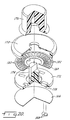
- Fig. 27 shows an alternate arrangement of a retainer incorporated in a pushbutton rotary switch.
- This switch has a cover 234 attached to a flexible carrier layer 236.
- the underside of the carrier has silver contacts 238.
- a rotor 240 has two couplers in the form of magnet pairs 242.
- the rotor also has a hollow central post 244.
- the rotor is attached to a knob 246 by an E-ring 248.
- a plunger 250 can move up and down in the bore of the post 244.
- the plunger is shown resting on top of the carrier 236. Alternately there may be an opening in the carrier allowing the plunger to extend through into contact with a retainer hub 258.
- Two twin-ball armatures 252 are fixed in receptacles 254 of a ball retainer.
- the retainer includes a web 256 joining the receptacles to a central hub 258.
- the hub is aligned with the plunger 250 and directly above the contacts of a membrane switch.
- the membrane switch includes a membrane 260, spacer 262 and substrate 264, with facing contacts 266 on the inside surfaces of the membrane and substrate. Pressure on the top of the plunger 250 is transferred by the hub 258 to the membrane, pushing it through an opening in the spacer to bring contacts 264 into engagement.
- the hub may alternately include a small button or nodule on its underside to further concentrate the actuating force.
- Fig. 28 shows a V-channel ball armature device. As with the other devices shown herein this could be either a switch or potentiometer, depending on the arrangement of the electrodes.
- the device includes a carrier block 268 having a V-shaped channel 270 or groove in one surface. There are electrodes 272 formed on the sloped sides of the channel.
- a single ball armature 274 rides in the channel.
- a coupler 276 is movable on the carrier block side opposite the channel for the purpose of moving the ball 274 back and forth in the channel. This arrangement permits a single ball armature.
- the channel could have a devious path with corners or curves to define a complex actuating pattern, e.g., the shifting pattern of a five-speed transmission.
Landscapes
- Physics & Mathematics (AREA)
- General Physics & Mathematics (AREA)
- Rotary Switch, Piano Key Switch, And Lever Switch (AREA)
- Push-Button Switches (AREA)
- Adjustable Resistors (AREA)
Claims (4)
- Elektrischer Schalter, der einen Träger (166) mit einer ersten und einer zweiten Fläche, eine Gruppe von Elektroden, die an einer der Trägerflächen angeordnet ist und wenigstens ein Paar beabstandeter Schalterkontakte bildet, sowie ein Betätigungselement zum selektiven Öffnen oder Schließen der Schalterkontakte umfasst, wobei das Betätigungselement einen elektrisch leitenden Anker (168), der an der einen der Trägerflächen angeordnet ist, und einen Koppler (170) umfasst, der beweglich an der anderen der Trägerflächen angebracht ist, wobei der Koppler (170) ein Permanentmagnet ist und der Anker (168) aus magnetischem Material besteht, so dass der Anker (168) durch die magnetische Anziehung zwischen dem Koppler (170) und dem Anker (168) normalerweise in Eingriff mit der einen Fläche des Trägers gehalten wird und Bewegung des Kopplers (170) entsprechende Bewegung des Ankers (168) in Kurzschlussbeziehung mit den Schalterkontakten und aus ihr heraus bewirkt, dadurch gekennzeichnet, dass ein Kappenelement (208) mit dem Träger (166) verbunden ist und eine Kammer bildet, in der sich der Anker (168) befindet.
- Schalter nach Anspruch 1, dadurch gekennzeichnet, dass ein Halter (178) an dem Träger (166) angebracht ist und das Kappenelement (208) an dem Halter (178) befestigt ist.
- Schalter nach Anspruch 2, dadurch gekennzeichnet, dass der Halter (178) des Weiteren Haken (216) umfasst, die mit dem Kappenelement (208) in Eingriff gebracht werden können.
- Schalter nach einem der vorangehenden Ansprüche, dadurch gekennzeichnet, dass er ein Anker-Rückhalteelement umfasst, das mit dem Anker (168) in der Kammer gedreht werden kann.
Applications Claiming Priority (3)
| Application Number | Priority Date | Filing Date | Title |
|---|---|---|---|
| US924334 | 1997-09-05 | ||
| US08/924,334 US5867082A (en) | 1995-06-02 | 1997-09-05 | Switch with magnetically-coupled armature |
| PCT/US1998/018293 WO1999013481A1 (en) | 1997-09-05 | 1998-09-03 | Switch with magnetically-coupled armature |
Publications (3)
| Publication Number | Publication Date |
|---|---|
| EP1010189A1 EP1010189A1 (de) | 2000-06-21 |
| EP1010189A4 EP1010189A4 (de) | 2002-07-31 |
| EP1010189B1 true EP1010189B1 (de) | 2006-07-26 |
Family
ID=25450093
Family Applications (1)
| Application Number | Title | Priority Date | Filing Date |
|---|---|---|---|
| EP98945854A Expired - Lifetime EP1010189B1 (de) | 1997-09-05 | 1998-09-03 | Schalter mit magnetisch gekoppeltem anker |
Country Status (7)
| Country | Link |
|---|---|
| US (1) | US5867082A (de) |
| EP (1) | EP1010189B1 (de) |
| CN (1) | CN1129158C (de) |
| AU (1) | AU727962B2 (de) |
| CA (1) | CA2303190C (de) |
| DE (1) | DE69835361T2 (de) |
| WO (1) | WO1999013481A1 (de) |
Families Citing this family (82)
| Publication number | Priority date | Publication date | Assignee | Title |
|---|---|---|---|---|
| US5990772A (en) * | 1995-06-02 | 1999-11-23 | Duraswitch Industries, Inc. | Pushbutton switch with magnetically coupled armature |
| US5977873A (en) * | 1998-03-04 | 1999-11-02 | Woods; Randall | Alarm switch |
| US6069552A (en) * | 1999-06-02 | 2000-05-30 | Duraswitch Industries, Inc. | Directionally sensitive switch |
| US6023213A (en) * | 1999-08-11 | 2000-02-08 | Duraswitch Industries, Inc. | Relocatable knob retention for magnetically actuated switch |
| US6186392B1 (en) * | 2000-01-21 | 2001-02-13 | Micron Technology, Inc. | Method and system for forming contacts on a semiconductor component by aligning and attaching ferromagnetic balls |
| US6305071B1 (en) * | 2000-03-30 | 2001-10-23 | Duraswitch Industries, Inc. | Method for converting a flat panel switch |
| US6607363B1 (en) * | 2002-02-20 | 2003-08-19 | Terumo Cardiovascular Systems Corporation | Magnetic detent for rotatable knob |
| JP4175007B2 (ja) * | 2002-03-22 | 2008-11-05 | 松下電器産業株式会社 | 回転操作型入力装置 |
| US6943705B1 (en) | 2002-05-03 | 2005-09-13 | Synaptics, Inc. | Method and apparatus for providing an integrated membrane switch and capacitive sensor |
| US7360932B2 (en) * | 2004-06-01 | 2008-04-22 | Donnelly Corporation | Mirror assembly for vehicle |
| DE10259569A1 (de) * | 2002-12-19 | 2004-07-01 | Hilti Ag | Elektrohandwerkzeugmaschine mit kontaktlosem elektrischen Handschalter |
| US7105754B2 (en) * | 2003-06-03 | 2006-09-12 | Fender Musical Instruments Corporation | Multi-functional control assembly for use in electric guitars |
| EP1484775A1 (de) * | 2003-06-05 | 2004-12-08 | Siemens Aktiengesellschaft | Koppelvorrichtung für Geräte mit drehbaren Schaltelementen |
| US6677843B1 (en) * | 2003-06-06 | 2004-01-13 | Datahand Systems, Inc. | Magnetically coupled pushbutton plunger switch |
| JP2006004711A (ja) * | 2004-06-16 | 2006-01-05 | Alps Electric Co Ltd | 複合入力装置 |
| US7598696B2 (en) * | 2004-08-31 | 2009-10-06 | Medtronic, Inc. | Surgical apparatus including a hand-activated, control assembly and method of using same |
| US8657808B2 (en) | 2004-08-31 | 2014-02-25 | Medtronic, Inc. | Surgical apparatus including a hand-activated, cable assembly and method of using same |
| US20060243122A1 (en) * | 2005-05-02 | 2006-11-02 | James Carson | Musical instrument mounting adapter |
| DE202005010424U1 (de) * | 2005-06-30 | 2005-12-29 | Malzahn, Heinz Herbert | Kontaktloser Abgriff auf Widerstandsflächen (Potenziometer) durch Permanentmagnete |
| TWM282745U (en) * | 2005-07-29 | 2005-12-11 | Homeease Ind Co Ltd | An improved temperature switch |
| CA2633821C (en) * | 2005-12-29 | 2012-02-14 | Illinois Tool Works Inc. | Pad printer with pad coupler and printing pad |
| US20080023229A1 (en) * | 2006-05-16 | 2008-01-31 | Schlumberger Technology Corporation | Tri stable actuator apparatus and method |
| JP4758322B2 (ja) * | 2006-06-09 | 2011-08-24 | 株式会社東海理化電機製作所 | スイッチ装置 |
| DE102007005362B3 (de) * | 2006-10-30 | 2008-02-14 | Siemens Ag | Betätigungselement |
| WO2008112778A2 (en) | 2007-03-12 | 2008-09-18 | Touchsensor Technologies Llc | Haptic feedback system and method |
| DE102007025279A1 (de) * | 2007-05-31 | 2008-12-04 | Valeo Klimasysteme Gmbh | Elektrischer Schalter mit Magnetbetätigung |
| US7820931B2 (en) * | 2007-07-25 | 2010-10-26 | Symbol Technologies, Inc. | Trigger arrangement with feedback response |
| US8970496B2 (en) * | 2008-04-15 | 2015-03-03 | Razer (Asia-Pacific) Pte. Ltd. | Ergonomic slider-based selector |
| US8465161B2 (en) * | 2008-10-14 | 2013-06-18 | Magna Mirrors Of America, Inc. | Interior rearview mirror assembly with button module |
| US8138860B2 (en) * | 2009-07-29 | 2012-03-20 | Spectra Symbol, Corp. | Magnetically-activated membrane potentiometer |
| US8284015B1 (en) * | 2009-09-03 | 2012-10-09 | Van Eyck Jerry J | Easily sanitized control device |
| JP2012138167A (ja) * | 2009-09-30 | 2012-07-19 | Nec Corp | アナログポインティングキー構造 |
| KR101628396B1 (ko) * | 2010-11-26 | 2016-06-08 | 현대자동차주식회사 | 차량용 햅틱 스크롤 휠 스위치 |
| US8309870B2 (en) | 2011-01-04 | 2012-11-13 | Cody George Peterson | Leveled touchsurface with planar translational responsiveness to vertical travel |
| US8912458B2 (en) | 2011-01-04 | 2014-12-16 | Synaptics Incorporated | Touchsurface with level and planar translational travel responsiveness |
| US9324515B2 (en) | 2012-08-06 | 2016-04-26 | Synaptics Incorporated | Touchsurface assembly utilizing magnetically enabled hinge |
| US9177733B2 (en) | 2012-08-06 | 2015-11-03 | Synaptics Incorporated | Touchsurface assemblies with linkages |
| US9218927B2 (en) | 2012-08-06 | 2015-12-22 | Synaptics Incorporated | Touchsurface assembly with level and planar translational responsiveness via a buckling elastic component |
| US9040851B2 (en) | 2012-08-06 | 2015-05-26 | Synaptics Incorporated | Keycap assembly with an interactive spring mechanism |
| FR2999779B1 (fr) * | 2012-12-19 | 2015-02-13 | C & K Components Sas | "agencement de commutateur electrique et dispositif pour la commande d'un appareil comportant un tel agencement" |
| US9384919B2 (en) | 2013-03-14 | 2016-07-05 | Synaptics Incorporated | Touchsurface assembly having key guides formed in a sheet metal component |
| US9213372B2 (en) | 2013-04-19 | 2015-12-15 | Synaptics Incorporated | Retractable keyboard keys |
| US9753436B2 (en) | 2013-06-11 | 2017-09-05 | Apple Inc. | Rotary input mechanism for an electronic device |
| KR102087349B1 (ko) | 2013-08-09 | 2020-04-24 | 애플 인크. | 전자 디바이스용 촉각 스위치 |
| WO2015088492A1 (en) | 2013-12-10 | 2015-06-18 | Apple Inc. | Input friction mechanism for rotary inputs of electronic devices |
| US10048802B2 (en) | 2014-02-12 | 2018-08-14 | Apple Inc. | Rejection of false turns of rotary inputs for electronic devices |
| US10190891B1 (en) | 2014-07-16 | 2019-01-29 | Apple Inc. | Optical encoder for detecting rotational and axial movement |
| KR102130259B1 (ko) | 2014-09-02 | 2020-07-03 | 애플 인크. | 웨어러블 전자 디바이스 |
| US9829350B2 (en) * | 2014-09-09 | 2017-11-28 | Apple Inc. | Magnetically coupled optical encoder |
| US10145712B2 (en) | 2014-09-09 | 2018-12-04 | Apple Inc. | Optical encoder including diffuser members |
| ES2537605B1 (es) * | 2015-03-03 | 2016-01-25 | Seat, S.A. | Dispositivo actuador para unidad de control y procedimiento de control de un dispositivo actuador para unidad de control |
| KR101940943B1 (ko) | 2015-03-05 | 2019-01-21 | 애플 인크. | 방향 종속 광학 특성을 갖는 광학 인코더 |
| US9651405B1 (en) | 2015-03-06 | 2017-05-16 | Apple Inc. | Dynamic adjustment of a sampling rate for an optical encoder |
| KR101993073B1 (ko) | 2015-03-08 | 2019-06-25 | 애플 인크. | 회전가능 및 병진가능한 입력 메커니즘을 위한 압축성 밀봉부 |
| US10018966B2 (en) | 2015-04-24 | 2018-07-10 | Apple Inc. | Cover member for an input mechanism of an electronic device |
| US9977456B2 (en) * | 2015-04-29 | 2018-05-22 | Advanced Input Devices, Inc. | Magnetic detenting configuration for custom encoder |
| CN105161341B (zh) * | 2015-08-12 | 2017-06-16 | 珠海市智迪科技股份有限公司 | 一种磁悬浮按键及键盘 |
| US10503271B2 (en) | 2015-09-30 | 2019-12-10 | Apple Inc. | Proximity detection for an input mechanism of an electronic device |
| US9891651B2 (en) | 2016-02-27 | 2018-02-13 | Apple Inc. | Rotatable input mechanism having adjustable output |
| US10551798B1 (en) | 2016-05-17 | 2020-02-04 | Apple Inc. | Rotatable crown for an electronic device |
| US10061399B2 (en) | 2016-07-15 | 2018-08-28 | Apple Inc. | Capacitive gap sensor ring for an input device |
| US10019097B2 (en) | 2016-07-25 | 2018-07-10 | Apple Inc. | Force-detecting input structure |
| US10510501B2 (en) * | 2017-04-19 | 2019-12-17 | Danfoss Power Solutions Inc. | Rotary knob controller |
| US10664074B2 (en) | 2017-06-19 | 2020-05-26 | Apple Inc. | Contact-sensitive crown for an electronic watch |
| JP6771102B2 (ja) | 2017-06-20 | 2020-10-21 | 株式会社フジクラ | スイッチ |
| US10962935B1 (en) | 2017-07-18 | 2021-03-30 | Apple Inc. | Tri-axis force sensor |
| US10592008B1 (en) | 2017-09-05 | 2020-03-17 | Apple Inc. | Mouse having a shape-changing enclosure |
| US10203662B1 (en) | 2017-09-25 | 2019-02-12 | Apple Inc. | Optical position sensor for a crown |
| DE102017128820A1 (de) * | 2017-12-05 | 2019-06-06 | Vorwerk & Co. Interholding Gmbh | Betätigungseinrichtung mit Magneten |
| US11360440B2 (en) | 2018-06-25 | 2022-06-14 | Apple Inc. | Crown for an electronic watch |
| US11561515B2 (en) | 2018-08-02 | 2023-01-24 | Apple Inc. | Crown for an electronic watch |
| US11181863B2 (en) | 2018-08-24 | 2021-11-23 | Apple Inc. | Conductive cap for watch crown |
| US12259690B2 (en) | 2018-08-24 | 2025-03-25 | Apple Inc. | Watch crown having a conductive surface |
| CN209560398U (zh) | 2018-08-24 | 2019-10-29 | 苹果公司 | 电子表 |
| CN209625187U (zh) | 2018-08-30 | 2019-11-12 | 苹果公司 | 电子手表和电子设备 |
| US11194298B2 (en) | 2018-08-30 | 2021-12-07 | Apple Inc. | Crown assembly for an electronic watch |
| US11194299B1 (en) | 2019-02-12 | 2021-12-07 | Apple Inc. | Variable frictional feedback device for a digital crown of an electronic watch |
| US11550268B2 (en) | 2020-06-02 | 2023-01-10 | Apple Inc. | Switch module for electronic crown assembly |
| US11269376B2 (en) | 2020-06-11 | 2022-03-08 | Apple Inc. | Electronic device |
| US11747919B1 (en) * | 2021-05-14 | 2023-09-05 | Apple Inc. | Multi-input for rotating and translating crown modules |
| US12092996B2 (en) | 2021-07-16 | 2024-09-17 | Apple Inc. | Laser-based rotation sensor for a crown of an electronic watch |
| US12189347B2 (en) | 2022-06-14 | 2025-01-07 | Apple Inc. | Rotation sensor for a crown of an electronic watch |
Family Cites Families (29)
| Publication number | Priority date | Publication date | Assignee | Title |
|---|---|---|---|---|
| US2410746A (en) * | 1942-09-02 | 1946-11-05 | Adele S Raettig | Magnetically operated switch |
| DE1055646B (de) * | 1955-12-22 | 1959-04-23 | Siemens Ag | Magnetische Kupplungsanordnung zur UEbertragung der Schaltkraft fuer elektrische Schalter durch eine unmagnetische Trennwand hindurch |
| DE1144368B (de) * | 1959-02-07 | 1963-02-28 | Telefonbau | Anordnung zum OEffnen oder Schliessen von elektrischen Stromkreisen |
| FR1329674A (fr) * | 1962-05-02 | 1963-06-14 | Contacteur magnétique | |
| FR2136970B1 (de) * | 1971-05-10 | 1973-05-11 | Webb Co Jervis B | |
| JPS5218390B2 (de) * | 1973-04-03 | 1977-05-21 | ||
| US3879602A (en) * | 1973-06-11 | 1975-04-22 | N Dimensions | Keyboard |
| US4068202A (en) * | 1976-06-07 | 1978-01-10 | Walter F. Wessendorf, Jr. | Reciprocable magnet switch |
| US4101857A (en) * | 1976-09-30 | 1978-07-18 | Toole Lawrence P O | Externally-programable switch |
| US4203013A (en) * | 1976-10-26 | 1980-05-13 | Serras Paulet Edouard | Alphanumeric control keyboard with depressible keys for electric or electronic machines |
| FR2370350A1 (fr) * | 1976-11-05 | 1978-06-02 | Serras Paulet Edouard | Commutateur rotatif, a aimants mobiles |
| FR2443130A1 (fr) * | 1978-11-29 | 1980-06-27 | Serras Paulet Edouard | Clavier de commande de dispositifs electriques ou electroniques |
| JPS6026430Y2 (ja) * | 1980-11-19 | 1985-08-09 | 株式会社 千野製作所 | 切換器 |
| US4370631A (en) * | 1981-01-22 | 1983-01-25 | The United States Of America As Represented By The Secretary Of The Navy | Waveguide switch |
| SE8400288L (sv) * | 1984-01-20 | 1985-07-21 | Anders Edvard Trell | Anordning for tagning och settning av blodsenkeprov |
| DE3408599A1 (de) * | 1984-03-09 | 1985-09-19 | MIT Wilde Membran Impuls Technik GmbH, 5828 Ennepetal | Bauelement fuer die vermittlungstechnik |
| US4603309A (en) * | 1984-05-25 | 1986-07-29 | Honeywell Inc. | Switching high speed digital pulses |
| SE455440B (sv) * | 1986-11-17 | 1988-07-11 | Autoliv Dev | Kontaktanordning for avgivande av elektriska signaler i beroende av en rorlig kropps lege |
| US4916275A (en) * | 1988-04-13 | 1990-04-10 | Square D Company | Tactile membrane switch assembly |
| JPH0741122Y2 (ja) * | 1989-11-28 | 1995-09-20 | 林原 健 | 密閉型可変抵抗器 |
| DE9003955U1 (de) * | 1990-04-05 | 1990-06-13 | Westra Electronic Gmbh, 8901 Welden | Stufig verstellbarer Drehknopf für elektronische Anwendungen |
| US5268660A (en) * | 1990-05-29 | 1993-12-07 | Cappelli Guido G | Quadrant driver for microwave switches |
| US5365155A (en) * | 1990-10-22 | 1994-11-15 | Marquardt Gmbh | Rotational speed control and use of same to control the rotational speed of an electric hand tool motor |
| JPH05258641A (ja) * | 1992-03-16 | 1993-10-08 | Matsushita Electric Ind Co Ltd | パネルスイッチ |
| US5332992A (en) * | 1993-04-06 | 1994-07-26 | Randall Woods | Security alarm switch |
| US5510589A (en) * | 1994-02-28 | 1996-04-23 | Intermec Corporation | High-life sealed switch assembly with tactile feedback |
| US5666096A (en) * | 1995-06-02 | 1997-09-09 | Van Zeeland; Anthony J. | Switch with magnetically-coupled armature |
| US5523730C1 (en) * | 1995-06-02 | 2002-01-15 | Van Anthony J Zeeland | Switch with mangnetically-coupled armature |
| US5717176A (en) * | 1996-07-17 | 1998-02-10 | United Technologies Automotive, Inc. | Sequentially operated membrane switches |
-
1997
- 1997-09-05 US US08/924,334 patent/US5867082A/en not_active Expired - Lifetime
-
1998
- 1998-09-03 CA CA002303190A patent/CA2303190C/en not_active Expired - Fee Related
- 1998-09-03 EP EP98945854A patent/EP1010189B1/de not_active Expired - Lifetime
- 1998-09-03 WO PCT/US1998/018293 patent/WO1999013481A1/en not_active Ceased
- 1998-09-03 AU AU93004/98A patent/AU727962B2/en not_active Ceased
- 1998-09-03 DE DE69835361T patent/DE69835361T2/de not_active Expired - Lifetime
- 1998-09-03 CN CN98810707.4A patent/CN1129158C/zh not_active Expired - Fee Related
Also Published As
| Publication number | Publication date |
|---|---|
| CA2303190C (en) | 2003-08-05 |
| EP1010189A4 (de) | 2002-07-31 |
| US5867082A (en) | 1999-02-02 |
| WO1999013481A1 (en) | 1999-03-18 |
| CN1278360A (zh) | 2000-12-27 |
| DE69835361T2 (de) | 2007-08-16 |
| AU9300498A (en) | 1999-03-29 |
| CA2303190A1 (en) | 1999-03-18 |
| EP1010189A1 (de) | 2000-06-21 |
| DE69835361D1 (de) | 2006-09-07 |
| CN1129158C (zh) | 2003-11-26 |
| AU727962B2 (en) | 2001-01-04 |
Similar Documents
| Publication | Publication Date | Title |
|---|---|---|
| EP1010189B1 (de) | Schalter mit magnetisch gekoppeltem anker | |
| EP0746006B1 (de) | Schalter mit magnetisch gekoppeltem Anker | |
| EP1154451B1 (de) | Schalter mit magnetisch gekoppeltem Anker | |
| MXPA96002095A (es) | Conmutador con armadura magneticamente acoplada | |
| AU750372B2 (en) | Pushbutton switch with magnetically coupled armature | |
| US6392515B1 (en) | Magnetic switch with multi-wide actuator | |
| US6369692B1 (en) | Directionally sensitive switch | |
| US6922123B2 (en) | Magnetic detent action for switches | |
| EP0901059B1 (de) | Multifunktionssteuerknüppel | |
| WO2001075920A1 (en) | Method and kit for converting a flat panel switch | |
| EP0189132B1 (de) | Tastaturgerät mit Kontakten mit magnetischer Schnappbetätigung | |
| WO2001011641A1 (en) | Relocatable knob retention for magnetically actuated switch | |
| MXPA00002348A (es) | Interruptor con armadura acoplada magneticamente | |
| JP2000149720A (ja) | 押釦スイッチ付き回転式電子部品 | |
| JP3579960B2 (ja) | プッシュスイッチ付回転操作型電子部品 | |
| VanZoest et al. | A Novel Innovation for Appliance Control Panel Design | |
| US20060221053A1 (en) | Drum control device for an electronic apparatus |
Legal Events
| Date | Code | Title | Description |
|---|---|---|---|
| PUAI | Public reference made under article 153(3) epc to a published international application that has entered the european phase |
Free format text: ORIGINAL CODE: 0009012 |
|
| 17P | Request for examination filed |
Effective date: 20000331 |
|
| AK | Designated contracting states |
Kind code of ref document: A1 Designated state(s): DE ES FR GB IT NL |
|
| A4 | Supplementary search report drawn up and despatched |
Effective date: 20020613 |
|
| AK | Designated contracting states |
Kind code of ref document: A4 Designated state(s): DE ES FR GB IT NL |
|
| RIC1 | Information provided on ipc code assigned before grant |
Free format text: 7H 01H 13/70 A, 7A 61B 5/14 B, 7H 01H 9/00 B, 7G 01D 5/06 B |
|
| 17Q | First examination report despatched |
Effective date: 20050525 |
|
| GRAP | Despatch of communication of intention to grant a patent |
Free format text: ORIGINAL CODE: EPIDOSNIGR1 |
|
| RAP1 | Party data changed (applicant data changed or rights of an application transferred) |
Owner name: DURASWITCH INDUSTRIES, INC. |
|
| RIC1 | Information provided on ipc code assigned before grant |
Ipc: H01H 9/00 20060101ALI20060131BHEP Ipc: H01H 13/70 20060101AFI20060131BHEP |
|
| GRAS | Grant fee paid |
Free format text: ORIGINAL CODE: EPIDOSNIGR3 |
|
| GRAA | (expected) grant |
Free format text: ORIGINAL CODE: 0009210 |
|
| AK | Designated contracting states |
Kind code of ref document: B1 Designated state(s): DE ES FR GB IT NL |
|
| PG25 | Lapsed in a contracting state [announced via postgrant information from national office to epo] |
Ref country code: NL Free format text: LAPSE BECAUSE OF FAILURE TO SUBMIT A TRANSLATION OF THE DESCRIPTION OR TO PAY THE FEE WITHIN THE PRESCRIBED TIME-LIMIT Effective date: 20060726 Ref country code: IT Free format text: LAPSE BECAUSE OF FAILURE TO SUBMIT A TRANSLATION OF THE DESCRIPTION OR TO PAY THE FEE WITHIN THE PRE;WARNING: LAPSES OF ITALIAN PATENTS WITH EFFECTIVE DATE BEFORE 2007 MAY HAVE OCCURRED AT ANY TIME BEFORE 2007. THE CORRECT EFFECTIVE DATE MAY BE DIFFERENT FROM THE ONE RECORDED.SCRIBED TIME-LIMIT Effective date: 20060726 |
|
| REG | Reference to a national code |
Ref country code: GB Ref legal event code: FG4D |
|
| REF | Corresponds to: |
Ref document number: 69835361 Country of ref document: DE Date of ref document: 20060907 Kind code of ref document: P |
|
| PG25 | Lapsed in a contracting state [announced via postgrant information from national office to epo] |
Ref country code: ES Free format text: LAPSE BECAUSE OF FAILURE TO SUBMIT A TRANSLATION OF THE DESCRIPTION OR TO PAY THE FEE WITHIN THE PRESCRIBED TIME-LIMIT Effective date: 20061106 |
|
| NLV1 | Nl: lapsed or annulled due to failure to fulfill the requirements of art. 29p and 29m of the patents act | ||
| EN | Fr: translation not filed | ||
| PLBE | No opposition filed within time limit |
Free format text: ORIGINAL CODE: 0009261 |
|
| STAA | Information on the status of an ep patent application or granted ep patent |
Free format text: STATUS: NO OPPOSITION FILED WITHIN TIME LIMIT |
|
| GBPC | Gb: european patent ceased through non-payment of renewal fee |
Effective date: 20061026 |
|
| 26N | No opposition filed |
Effective date: 20070427 |
|
| PG25 | Lapsed in a contracting state [announced via postgrant information from national office to epo] |
Ref country code: GB Free format text: LAPSE BECAUSE OF NON-PAYMENT OF DUE FEES Effective date: 20061026 |
|
| PG25 | Lapsed in a contracting state [announced via postgrant information from national office to epo] |
Ref country code: FR Free format text: LAPSE BECAUSE OF FAILURE TO SUBMIT A TRANSLATION OF THE DESCRIPTION OR TO PAY THE FEE WITHIN THE PRESCRIBED TIME-LIMIT Effective date: 20070511 |
|
| PG25 | Lapsed in a contracting state [announced via postgrant information from national office to epo] |
Ref country code: FR Free format text: LAPSE BECAUSE OF FAILURE TO SUBMIT A TRANSLATION OF THE DESCRIPTION OR TO PAY THE FEE WITHIN THE PRESCRIBED TIME-LIMIT Effective date: 20060726 |
|
| PGFP | Annual fee paid to national office [announced via postgrant information from national office to epo] |
Ref country code: DE Payment date: 20150825 Year of fee payment: 18 |
|
| REG | Reference to a national code |
Ref country code: DE Ref legal event code: R119 Ref document number: 69835361 Country of ref document: DE |
|
| PG25 | Lapsed in a contracting state [announced via postgrant information from national office to epo] |
Ref country code: DE Free format text: LAPSE BECAUSE OF NON-PAYMENT OF DUE FEES Effective date: 20170401 |