US10061399B2 - Capacitive gap sensor ring for an input device - Google Patents
Capacitive gap sensor ring for an input device Download PDFInfo
- Publication number
- US10061399B2 US10061399B2 US15/210,917 US201615210917A US10061399B2 US 10061399 B2 US10061399 B2 US 10061399B2 US 201615210917 A US201615210917 A US 201615210917A US 10061399 B2 US10061399 B2 US 10061399B2
- Authority
- US
- United States
- Prior art keywords
- capacitive elements
- electronic device
- cap
- capacitive
- input device
- Prior art date
- Legal status (The legal status is an assumption and is not a legal conclusion. Google has not performed a legal analysis and makes no representation as to the accuracy of the status listed.)
- Active, expires
Links
Images


Classifications
-
- G—PHYSICS
- G06—COMPUTING OR CALCULATING; COUNTING
- G06F—ELECTRIC DIGITAL DATA PROCESSING
- G06F3/00—Input arrangements for transferring data to be processed into a form capable of being handled by the computer; Output arrangements for transferring data from processing unit to output unit, e.g. interface arrangements
- G06F3/01—Input arrangements or combined input and output arrangements for interaction between user and computer
- G06F3/03—Arrangements for converting the position or the displacement of a member into a coded form
- G06F3/033—Pointing devices displaced or positioned by the user, e.g. mice, trackballs, pens or joysticks; Accessories therefor
- G06F3/0338—Pointing devices displaced or positioned by the user, e.g. mice, trackballs, pens or joysticks; Accessories therefor with detection of limited linear or angular displacement of an operating part of the device from a neutral position, e.g. isotonic or isometric joysticks
-
- G—PHYSICS
- G04—HOROLOGY
- G04C—ELECTROMECHANICAL CLOCKS OR WATCHES
- G04C3/00—Electromechanical clocks or watches independent of other time-pieces and in which the movement is maintained by electric means
- G04C3/001—Electromechanical switches for setting or display
- G04C3/005—Multiple switches
-
- G—PHYSICS
- G04—HOROLOGY
- G04C—ELECTROMECHANICAL CLOCKS OR WATCHES
- G04C3/00—Electromechanical clocks or watches independent of other time-pieces and in which the movement is maintained by electric means
- G04C3/001—Electromechanical switches for setting or display
- G04C3/007—Electromechanical contact-making and breaking devices acting as pulse generators for setting
-
- G—PHYSICS
- G04—HOROLOGY
- G04G—ELECTRONIC TIME-PIECES
- G04G21/00—Input or output devices integrated in time-pieces
- G04G21/08—Touch switches specially adapted for time-pieces
-
- G—PHYSICS
- G06—COMPUTING OR CALCULATING; COUNTING
- G06F—ELECTRIC DIGITAL DATA PROCESSING
- G06F1/00—Details not covered by groups G06F3/00 - G06F13/00 and G06F21/00
- G06F1/16—Constructional details or arrangements
- G06F1/1613—Constructional details or arrangements for portable computers
- G06F1/163—Wearable computers, e.g. on a belt
-
- G—PHYSICS
- G06—COMPUTING OR CALCULATING; COUNTING
- G06F—ELECTRIC DIGITAL DATA PROCESSING
- G06F3/00—Input arrangements for transferring data to be processed into a form capable of being handled by the computer; Output arrangements for transferring data from processing unit to output unit, e.g. interface arrangements
- G06F3/01—Input arrangements or combined input and output arrangements for interaction between user and computer
- G06F3/03—Arrangements for converting the position or the displacement of a member into a coded form
- G06F3/033—Pointing devices displaced or positioned by the user, e.g. mice, trackballs, pens or joysticks; Accessories therefor
- G06F3/0354—Pointing devices displaced or positioned by the user, e.g. mice, trackballs, pens or joysticks; Accessories therefor with detection of two-dimensional [2D] relative movements between the device, or an operating part thereof, and a plane or surface, e.g. 2D mice, trackballs, pens or pucks
- G06F3/03547—Touch pads, in which fingers can move on a surface
-
- G—PHYSICS
- G06—COMPUTING OR CALCULATING; COUNTING
- G06F—ELECTRIC DIGITAL DATA PROCESSING
- G06F3/00—Input arrangements for transferring data to be processed into a form capable of being handled by the computer; Output arrangements for transferring data from processing unit to output unit, e.g. interface arrangements
- G06F3/01—Input arrangements or combined input and output arrangements for interaction between user and computer
- G06F3/03—Arrangements for converting the position or the displacement of a member into a coded form
- G06F3/033—Pointing devices displaced or positioned by the user, e.g. mice, trackballs, pens or joysticks; Accessories therefor
- G06F3/0362—Pointing devices displaced or positioned by the user, e.g. mice, trackballs, pens or joysticks; Accessories therefor with detection of one-dimensional [1D] translations or rotations of an operating part of the device, e.g. scroll wheels, sliders, knobs, rollers or belts
-
- G—PHYSICS
- G06—COMPUTING OR CALCULATING; COUNTING
- G06F—ELECTRIC DIGITAL DATA PROCESSING
- G06F3/00—Input arrangements for transferring data to be processed into a form capable of being handled by the computer; Output arrangements for transferring data from processing unit to output unit, e.g. interface arrangements
- G06F3/01—Input arrangements or combined input and output arrangements for interaction between user and computer
- G06F3/03—Arrangements for converting the position or the displacement of a member into a coded form
- G06F3/041—Digitisers, e.g. for touch screens or touch pads, characterised by the transducing means
- G06F3/044—Digitisers, e.g. for touch screens or touch pads, characterised by the transducing means by capacitive means
- G06F3/0446—Digitisers, e.g. for touch screens or touch pads, characterised by the transducing means by capacitive means using a grid-like structure of electrodes in at least two directions, e.g. using row and column electrodes
-
- G—PHYSICS
- G06—COMPUTING OR CALCULATING; COUNTING
- G06F—ELECTRIC DIGITAL DATA PROCESSING
- G06F2203/00—Indexing scheme relating to G06F3/00 - G06F3/048
- G06F2203/033—Indexing scheme relating to G06F3/033
- G06F2203/0339—Touch strips, e.g. orthogonal touch strips to control cursor movement or scrolling; single touch strip to adjust parameter or to implement a row of soft keys
-
- G—PHYSICS
- G06—COMPUTING OR CALCULATING; COUNTING
- G06F—ELECTRIC DIGITAL DATA PROCESSING
- G06F2203/00—Indexing scheme relating to G06F3/00 - G06F3/048
- G06F2203/041—Indexing scheme relating to G06F3/041 - G06F3/045
- G06F2203/04105—Pressure sensors for measuring the pressure or force exerted on the touch surface without providing the touch position
Definitions
- the described embodiments relate generally to input devices. More particularly, the present embodiments relate to a capacitive sensor that can detect multiple types of motion of an input device.
- Electronic devices include a variety of different input and/or output devices for receiving input from and/or providing output to users.
- Examples of input and/or output devices include keyboards, touch screens, displays, joysticks, microphones, speakers, watch crowns, trackpads, track balls, and so on.
- Some input devices include a moveable member and one or more sensors or other components that detect the movement of the moveable member.
- keyboards may include a number of keycaps that can be pressed to activate one or more switches. Activating a switch may provide input to the electronic device.
- An input mechanism for a portable electronic device includes a manipulation mechanism, such as a cap or shaft that is moveable in multiple directions.
- the input mechanism also includes capacitive sensors arranged in multiple planes with respect to the manipulation mechanism that are associated with the multiple directions of movement.
- the capacitive sensors have first capacitive elements coupled to the manipulation mechanism, second capacitive elements, and a dielectric positioned between. Movement of the manipulation mechanism alters the positions of the first and second capacitive elements with respect to each other. The movement is determinable based on capacitance changes that result therefrom.
- a wearable electronic device has a multi-directional input device.
- the multi-directional input device includes a shaft, a cap operable to move with respect to the shaft, and a sensor coupling the cap to the shaft.
- the sensor includes an outer set of capacitive elements, an inner set of capacitive elements, a dielectric between the outer and inner sets of capacitive elements, and a returning structure.
- the returning structure is operable to allow movement of the outer set of capacitive elements with respect to the inner set of capacitive elements and return the outer set of capacitive elements to a default position.
- the dielectric is the returning structure
- a first element of the outer set of capacitive elements completely overlaps a first element of the inner set of capacitive elements.
- a first element of the outer set of capacitive elements is offset from a first element of the inner set of capacitive elements by a first distance and a second element of the outer set of capacitive elements is offset from a second element of the inner set of capacitive elements by a second distance.
- the first and second distances may be different.
- the shaft is fixed. In other examples, the shaft is moveable.
- the dielectric is at least one of silicone or adhesive. In other examples, the dielectric is an air gap.
- the electronic device is operable to determine rotation of the cap with respect to the shaft, lateral translation of the cap with respect to the shaft, and horizontal translation of the cap with respect to the shaft.
- the electronic device may determine these movements based on capacitance changes between the outer and inner sets of capacitive elements.
- an electronic device has an input device.
- the input device includes a rotational manipulation mechanism, a first array of capacitive elements coupled to the manipulation mechanism, a second array of capacitive elements, and a dielectric that couples the first and second arrays of capacitive elements.
- the dielectric may operate as a seal for the electronic device. Movement of the manipulation mechanism generates capacitance changes between the first and second arrays of capacitive elements.
- the first array of capacitive elements is included in a first ring.
- the second array of capacitive elements is included in a second ring that is at least partially nested within the first ring.
- movement of the manipulation mechanism may alter at least one of a first overlap area or a first distance between a first pair of the first and second arrays of capacitive elements. Movement of the manipulation mechanism may also alter at least one of a second overlap area or a second distance between a second pair of the first and second arrays of capacitive elements.
- the first overlap area may be different from the second overlap area.
- the first distance may be different from the second distance.
- the manipulation mechanism is operable to rotate, press, and slide.
- the first array of capacitive elements has a different number of elements than the second array of capacitive elements.
- the first and second arrays of capacitive elements may experience a change in capacitance in response to a touch on the manipulation mechanism.
- an input device includes a fixed structure, a moveable member that is rotatable with respect to the fixed structure, a first set of conductors positioned around the moveable member, and a second set of conductors positioned around the fixed structure to define a gap between the first and second sets of conductors. Capacitance changes between the first and second sets of conductors indicate movement of the moveable element with respect to the fixed structure. At least one of the first set of conductors or the second set of conductors may be curved.
- a first conductor of the first set of conductors is transverse to a second conductor of the first set of conductors.
- a third conductor of the first set of conductors may be transverse to the second conductor of the first set of conductors.
- the input device is a watch crown. In other implementations, the input device is a joystick. In yet other implementations, the input device may be a variety of different input devices.
- FIG. 1 depicts an electronic device having a multi-directional input device.
- FIG. 2A depicts a first example cross-sectional view of the multi-directional input device of FIG. 1 , taken along line A-A of FIG. 1 .
- FIG. 2B depicts the multi-directional input device of FIG. 2A during translation.
- FIG. 2C depicts a state table illustrating example changes in capacitance of capacitive sensors, with respect to FIGS. 2A and 2B .
- FIG. 2D depicts the multi-directional input device of FIG. 2A during rotation.
- FIG. 2E depicts a state table illustrating example changes in capacitance of capacitive sensors, with respect to FIGS. 2A and 2D .
- FIG. 3A depicts a second example cross-sectional view of the multi-directional input device of FIG. 2A , where outer and inner sets of capacitive elements are offset from each other.
- FIG. 3B depicts a state table illustrating example changes in capacitance of capacitors, with respect to FIG. 3A and FIG. 3A with the cap rotated like shown in FIG. 2D .
- FIG. 4 depicts a third example cross-sectional view of the multi-directional input device of FIG. 2A where the outer set of capacitive elements includes more elements than the inner set of capacitive elements.
- FIG. 5 depicts a fourth example cross-sectional view of the multi-directional input device of FIG. 2A where the inner set of capacitive elements includes more elements than the outer set of capacitive elements.
- FIG. 6A depicts a second example cross-sectional view of the multi-directional input device of FIG. 1 , taken along line B-B of FIG. 1 .
- FIG. 6B depicts the multi-directional input device of FIG. 6A upon exertion of a force that translates the cap in a direction approximately perpendicular to the housing.
- FIG. 7 depicts another example cross-sectional view of the multi-directional input device of FIG. 6A , where one or more of the outer and inner sets of capacitive elements are offset from each other.
- FIG. 8 depicts a fifth example cross-sectional view of the multi-directional input device of FIG. 2A where the dielectric is an air gap and a biasing mechanism.
- FIG. 9 depicts a sixth example cross-sectional view of the multi-directional input device of FIG. 2A where the outer ring forms the cap.
- FIG. 10 depicts a flow chart illustrating an example method for operating a capacitive sensor for a directional input device. This example method may be performed by the multi-directional input devices of FIGS. 1-9 .
- the following disclosure relates to an input device that incorporates a moveable member.
- the moveable member can be manipulated in a variety of directions to provide input.
- the input device may also include one or more capacitive sensors with groups of capacitive elements positioned around the moveable member. Moving the moveable member may alter positions of some capacitive elements with respect to others, changing capacitances therebetween. The capacitance changes may be used to generate an input signal corresponding to the moveable member's motion.
- the senor may be a ring or partial ring of capacitive elements.
- the capacitive elements may include an outer set of conductors that is separated from an inner set of conductors by a dielectric. Force exerted to move a shaft, cap, or other structure coupled to the sensor may change the relative position of one or more of the sets of conductors with respect to other sets, changing capacitances therebetween.
- the dielectric may facilitate the change in relative position, and may return the capacitive elements to a default position after the force stops.
- Various embodiments detect movement in a variety of different directions.
- this movement may include translation in one or more directions, rotation, tilt, and so on.
- FIG. 1 depicts an electronic device 100 having a multi-directional input device 102 , which may incorporate a capacitive sensor as described below.
- the multi-directional input device 102 may include a cap 103 , crown, or other moveable member or rotational manipulation mechanism.
- the cap 103 may move in various directions when a user exerts force.
- the cap 103 may rotate with respect to a housing 101 of the electronic device 100 , press by translating horizontally toward and/or away from the housing 101 , slide by laterally translating in one or more directions approximately parallel to the housing 101 , tilt with respect to the housing 101 , and so on.
- the multi-directional input device 102 includes one or more capacitive sensors that detect movement of the cap 103 .
- Information about the movement may be determined based on one or more signals received from the capacitive sensor. For example, a type of motion, direction of motion, non-binary amount of force applied to cause the motion, and so on may be determined based on various capacitive sensor signals.
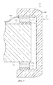
- FIG. 2A depicts a first example cross-sectional view of the multi-directional input device 102 of FIG. 1 , taken along line A-A of FIG. 1 .
- a capacitive sensor includes an outer ring 240 , including an outer set of capacitive elements 210 A- 210 C (or a first array of capacitive elements, first set of conductors, and so on) and an inner ring 241 , including an inner set of capacitive elements 211 A- 211 C (or a second array of capacitive elements, second set of conductors, and so on).
- a dielectric 212 separates and couples the outer and inner sets of capacitive elements 210 A- 210 C, 211 A- 211 C, and defines a gap therebetween.
- the outer set of capacitive elements 210 A- 210 C is coupled to the cap 103 , crown, or other rotational manipulation mechanism and the inner set of capacitive elements 211 A- 211 C is coupled to a fixed shaft 214 or other fixed structure or other component.
- the outer and inner rings 240 , 241 also include a number of spacers 215 , 216 (formed of insulating materials such as plastic, polymer, and so on) which respectively isolate the outer and inner sets of capacitive elements 210 A- 210 C, 211 A- 211 C from each other.
- the multi-directional input device 102 may include a returning structure.
- the returning structure may allow the outer set of capacitive elements 210 A- 210 C to move or otherwise alter their position with respect to the inner set of capacitive elements 211 A- 211 C when the cap 103 moves under a force.
- the returning structure may also return the outer set of capacitive elements 210 A- 210 C to their default positions after the exertion of the force.
- the returning structure may be the dielectric 212 .
- the dielectric 212 may be a deformable material, such as silicone or other polymers, suitable gels, foams, adhesive, and so on.
- the deformable material may allow the outer set of capacitive elements 210 A- 210 C to move or otherwise alter their position with respect to the inner set of capacitive elements 211 A- 211 C and may return the outer set of capacitive elements 210 A- 210 C to their default positions after the exertion of the force.
- Movement of the outer set of capacitive elements 210 A- 210 C with respect to the inner set of capacitive elements 211 A- 211 C may change capacitances therebetween.
- the capacitance between the outer and inner sets of capacitive elements 210 A- 210 C, 211 A- 211 C may be affected by the amount of overlapping area, the distance between the outer and inner sets of capacitive elements 210 A- 210 C, 211 A- 211 C, and so on.
- the outer set of capacitive elements 210 A- 210 C entirely overlap the inner set of capacitive elements 211 A- 211 C and are all the same distance apart. This corresponds to an absence of force exerted on the cap 103 .
- Capacitances, and/or changes in capacitances, between the outer and inner sets of capacitive elements 210 A- 210 C, 211 A- 211 C may be monitored. Any changes in capacitances (or instantaneous values of capacitance) may be analyzed to determine a type of motion of the cap 103 , direction of motion of the cap 103 , non-binary amount of force applied to cause the motion of the cap 103 , and/or other information about motion of the cap 103 with respect to the shaft 214 .
- the electronic device 100 (and/or processing unit or other controller thereof) may be operable to determine a variety of different movements of the cap 103 based on the capacitance changes.
- the electronic device 100 may determine rotation of the cap 103 with respect to the shaft 214 in one or more directions.
- the electronic device 100 may also determine translation of the cap 103 laterally and horizontally (in reference to FIG. 2A ) with respect to the shaft 214 (e.g., in at least two transverse planes, such as a plane parallel to the housing 101 and a plane perpendicular to the housing 101 ).
- the configuration of this first example multi-directional input device 102 may use a relatively small number of components without introducing excessive complexity. Further, the configuration of this first example multi-directional input device 102 may allow watertight or near-watertight sealing between the multi-directional input device 102 and the housing 101 , restricting the passage of contaminants such as dust or liquid.
- the dielectric 212 and/or the sensor itself may function as such a seal or gasket. In other implementations, other seals, gaskets, and so on may also be included.
- the outer set of capacitive elements 210 A- 210 C may be drive elements and the inner set of capacitive elements 211 A- 211 C may be sense elements.
- the drive and sense elements may be reversed.
- the drive and sense elements may be intermixed among the outer and inner sets of capacitive elements 210 A- 210 C, 211 A- 211 C.
- drive elements may be passive.
- the outer and inner sets of capacitive elements 210 A- 210 C, 211 A- 211 C are curved. Further, the outer and inner sets of capacitive elements 210 A- 210 C, 211 A- 211 C are positioned in multiple planes around the cap 103 in complete rings 240 , 241 , where the inner ring 241 is at least partially nested within the outer ring 240 .
- the outer capacitive element 210 C is transverse to the outer capacitive element 210 A (e.g., two different planes), which is itself transverse to the outer capacitive element 210 B (e.g., a third plane).
- this is an example.
- various capacitive elements may be positioned in different configurations without departing from the scope of the present disclosure, and/or may have any of a variety of shapes.
- the outer and inner sets of capacitive elements 210 A- 210 C, 211 A- 211 C may be configured in partial rings rather than the complete outer and inner rings 240 , 241 shown.
- FIG. 2B depicts the multi-directional input device 102 upon exertion of a force applied by a user 217 .
- This force laterally translates the cap 103 in the direction 230 approximately parallel to the housing 101 .
- Lateral translation causes the outer capacitive element 210 A to shift with respect to the inner capacitive element 211 A such that they are the same distance apart but have less overlapping area.
- Lateral translation also causes the outer capacitive element 210 B to move apart from the inner capacitive element 211 B such that they have the same overlapping area but the distance between has increased.
- lateral translation causes the outer capacitive element 210 C to approach the inner capacitive element 211 C such that the overlapping area is the same but the distance between has decreased.
- FIG. 2C depicts a state table illustrating example changes in capacitance between the outer and inner sets of capacitive elements 210 A- 210 C, 211 A- 211 C between the states shown in FIGS. 2A and 2B .
- the capacitances between the outer and inner sets of capacitive elements 210 A- 210 C, 211 A- 211 C in FIG. 2A are all the same value (represented as “X”) because all of outer and inner sets of capacitive elements 210 A- 210 C, 211 A- 211 C are the same distance apart and have the same overlapping area.
- X represented as “X”
- the decreased overlapping area between the outer capacitive element 210 A and the inner capacitive element 211 A results in a first changed capacitance less than X.
- the increased distance between the outer capacitive element 210 B and the inner capacitive element 211 B results in a second changed capacitance that is also less than X.
- the values of the first and second changed capacitances are different.
- the decreased distance between the outer capacitive element 210 C and the inner capacitive element 211 C results in a third changed capacitance that is greater than X.
- the electronic device 100 may determine that the cap 103 has laterally translated in the direction 230 shown in FIG. 2B .
- the electronic device 100 may also determine the non-binary amount of the force that caused the motion based on the magnitude of the capacitance changes and/or other capacitance change factors.
- an absolute evaluation of a current capacitance may be used to determine movement without reference to an initial capacitance.
- the electronic device 100 may analyze and compare the changed capacitances, or capacitance changes, in a variety of ways. For example, the electronic device 100 may consult one or more lookup tables stored in a non-transitory media in order to correlate the capacitance changes to various types of motion, direction of motion, amount of motion, amount of force, and so on. For example, decreased capacitance on only one side may indicate lateral motion in the opposite direction. By way of another example, decreased capacitance seen by all capacitive elements may indicate rotation.
- FIG. 2B depicts left/right, with reference to FIG. 2B , lateral or slide motion of the cap 103 .
- the cap 103 may also move laterally up/down (with reference to FIG. 2B ) and this motion may be detected based on capacitances between the outer and inner sets of capacitive elements 210 A- 210 C, 211 A- 211 C.
- This lateral up/down motion may operate similarly to the left/right lateral motion described above.
- the two motions may be recognized as different types of input.
- different types of input may be recognized for each different way that the FIG. 2B depicts left/right, with reference to FIG. 2B , lateral or slide motion of the cap 103 .
- the cap 103 may also move laterally up/down (with reference to FIG. 2B ) and this motion may be detected based on capacitances between the outer and inner sets of capacitive elements 210 A- 210 C, 211 A- 211 C may move with respect to each other.
- FIG. 2D depicts the multi-directional input device 102 of FIG. 2A upon exertion of a force applied by a user 217 that rotates the cap 103 in a direction 231 .
- This rotation causes all of the outer capacitive elements 210 A- 210 C to shift with respect to the respective inner capacitive elements 211 A- 211 C such that they are the same distance apart but have less overlapping area 232 A- 232 C.
- FIG. 2E depicts a state table illustrating example capacitances between the outer and inner sets of capacitive elements 210 A- 210 C, 211 A- 211 C, as they are in the state shown in FIG. 2A and in that of FIG. 2D .
- the capacitances between the outer and inner sets of capacitive elements 210 A- 210 C, 211 A- 211 C in FIG. 2A are all the same value, namely X.
- the decreased overlapping area 232 A- 232 C between the outer capacitive elements 210 A- 210 C and the respective inner capacitive elements 211 A- 211 C results in capacitances that are all less than X.
- These capacitances may be analyzed and compared to each other. Because all three capacitances decrease, the electronic device 100 may determine that the cap 103 has rotated.
- the capacitance changes between the outer and inner capacitive elements 210 A- 210 C, 211 A- 211 C are entirely caused by the changing overlapping area 232 A- 232 C due to rotation.
- the capacitance changes may not indicate the direction of the rotation as the same amount of rotation in either direction would result in the same change in overlapping area.
- a force exerted to rotate the cap 103 may also translate the cap 103 in a direction opposite the direction of the applied force, at least minimally.
- gaps (distances) between one or more of the outer and inner capacitive elements 210 A- 210 C, 211 A- 211 C would change and the three capacitance changes would not be precisely identical.
- These differences between the three capacitances may be analyzed in order to determine the direction of the rotation based on where the gaps are increasing and/or decreasing.
- FIG. 3A depicts a second example cross-sectional view of the multi-directional input device 102 of FIG. 2A where a number of the outer and inner sets of capacitive elements 310 A- 310 C, 311 A- 311 C are offset from each other (e.g., from the respective associated capacitive element 310 A- 310 C, 311 A- 311 C).
- the outer capacitive element 310 A is offset from the inner capacitive element 311 A in a first direction 331 by a first distance whereas the outer capacitive element 310 B is offset from the inner capacitive element 311 B in an opposite direction 333 by a second distance.
- the first and second distances may be different.
- the capacitive elements 310 A, 311 A are offset differently than the capacitive elements 310 B, 311 B.
- the overlapping area (and thus the capacitance) between the outer capacitive element 310 A and the inner capacitive element 311 A decreases if the cap 303 was rotated in the direction 331 and increases if the cap 303 was rotated in the opposite direction 333 .
- the overlapping area (and thus the capacitance) between the outer capacitive element 310 B and the inner capacitive element 311 B increases if the cap 303 was rotated in the direction 331 and decreases if the cap 303 was rotated in the opposite direction 333 .
- the three capacitance changes may be analyzed to determine the rotation of the cap 303 , the amount of rotation, and the direction of rotation.
- FIG. 3B depicts a state table illustrating example changes in capacitance between the outer and inner sets of capacitive elements 310 A- 310 C, 311 A- 311 C between the state shown in FIG. 3A and the state when the cap 303 is rotated in the direction 331 .
- the capacitances between the outer and inner sets of capacitive elements 310 A- 310 C, 311 A- 311 C in FIG. 3A are all different values (represented by “Y,” “Z,” and “X”) because all of the outer and inner sets of capacitive elements 310 A- 310 C, 311 A- 311 C have different overlapping areas.
- FIG. 3B depicts a state table illustrating example changes in capacitance between the outer and inner sets of capacitive elements 310 A- 310 C, 311 A- 311 C between the state shown in FIG. 3A and the state when the cap 303 is rotated in the direction 331 .
- the further decreased overlapping area between the outer capacitive element 310 A and the inner capacitive element 311 A results in a capacitance less than Y.
- the increased overlapping area between the outer capacitive element 310 B and the inner capacitive element 311 B results in a capacitance greater than Z.
- the decreased overlapping area between the outer capacitive element 310 C and the inner capacitive element 311 C is the same as in FIG. 2A , less than X.
- FIGS. 3A-3B illustrate an example configuration that results in different capacitance changes for different directions of rotation
- FIG. 4 depicts a third example cross-sectional view of the multi-directional input device 102 of FIG. 2A where the outer set of capacitive elements 410 A- 410 D includes more elements than the inner set of capacitive elements 411 A- 411 C.
- the additional capacitive element 410 D may not (or may minimally) capacitively couple with any of the inner set of capacitive elements 411 A- 411 C.
- the capacitive element 410 D and the capacitive element 411 A may capacitively couple as they begin to overlap. Based on this capacitive change, combined with the decreases in capacitance between the outer and inner sets of capacitive elements 410 A- 410 C, 411 A- 411 C due to the decreased overlap area between those elements, the electronic device 100 may determine that the cap 403 has rotated in the direction 431 .
- the capacitive element 410 D may capacitively couple with the capacitive element 411 C.
- this capacitive change combined with the decreases in capacitance between the outer and inner sets of capacitive elements 410 A- 410 C, 411 A- 411 C due to the decreased overlap area between those elements, indicates the rotation of the cap 403 in the opposite direction.
- FIG. 5 depicts a fourth example cross-sectional view of the multi-directional input device 102 of FIG. 2A where the inner set of capacitive elements 511 A- 511 D includes more elements than the outer set of capacitive elements 510 A- 510 C.
- the capacitive element 511 D may not (or may minimally) capacitively couple with any of the outer set of capacitive elements 510 A- 510 C.
- the cap 503 is rotated in the direction 531 , the capacitive element 511 D and the capacitive element 510 A may capacitively couple as they begin to overlap.
- the electronic device 100 may determine that the cap 503 has rotated in the direction 531 .
- the capacitive element 511 D may overlap the capacitive element 510 B.
- the capacitive element 511 D and the capacitive element 510 B may capacitively couple.
- This capacitance change combined with the decreases in capacitance between the outer and inner sets of capacitive elements 510 A- 510 C, 511 A- 511 C due to the decreased overlap area between those elements, indicates the rotation of the cap 503 in the opposite direction 533 .
- FIG. 6A depicts a second example cross-sectional view of the multi-directional input device 102 of FIG. 1 , taken along line B-B of FIG. 1 .
- one or more of the outer and inner sets of capacitive elements 210 A- 210 C, 211 A- 211 C may be connected to the electronic device 100 (and/or a component thereof, such as a processing unit or other controller) via flex circuits 218 A, 218 B and/or other conductive materials or communication connections.
- FIG. 6B depicts the multi-directional input device 102 of FIG. 6A upon exertion of a force by a user 217 that horizontally translates the cap 103 (e.g., in a direction 634 approximately perpendicular to the shaft 214 ). Horizontal translation of the cap 103 corresponds to a press motion. In this example, the cap 103 horizontally translates toward the shaft 214 and the housing.
- Horizontal translation of the cap 103 toward the housing changes the position of the outer and inner sets of capacitive elements 210 A- 210 C, 211 A- 211 C with respect to each other as well as spacers 215 , 216 .
- the spacers 215 , 216 are also separated by the dielectric 212 , and may be omitted in some embodiments. Due to the relative change in position between the outer and inner sets of capacitive elements, the capacitances decrease because the overlapping area decreases. As such, the electronic device 100 may determine from the capacitance changes that the cap 103 has horizontally translated in a direction 634 approximately perpendicular to the housing 101 .
- the capacitance changes may be the same whether the cap 103 horizontally translates by the same amount toward or away from the housing.
- the outer and inner sets of capacitive elements 210 A- 210 C, 211 A- 211 C may be configured such that capacitances change differently between the outer and inner sets of capacitive elements depending on whether the cap 103 moves toward or away from the housing 101 .
- Such configurations may include offsetting one or more of the outer and inner sets of capacitive elements 210 A- 210 C, 211 A- 211 C with respect to each other, such as in the horizontal direction 634 (e.g., approximately perpendicular to the housing 101 ) and similar to the offsets depicted in the example of FIGS. 3A-3B .
- FIG. 7 depicts another example cross-sectional view of the multi-directional input device 102 of FIG. 6A where one or more of the outer and inner sets of capacitive elements 710 A- 710 C, 711 A- 711 C are horizontally offset from each other. As shown, the capacitive elements 710 A, 711 A are offset in a direction 734 . As such, the capacitance between them will change differently depending on whether the cap 703 horizontally translates toward the shaft 714 or away from the shaft 714 . In some implementations, one or more other of the outer and inner sets of capacitive elements 710 B- 710 C, 711 B- 711 C may be offset from each other, and may be offset differently than the capacitive elements 710 A, 711 A.
- FIG. 7 illustrates an example configuration that results in different capacitance changes for translation toward and away from the housing 101
- the outer and inner sets of capacitive elements 710 A- 710 C, 711 A- 711 C may include one or more additional capacitive elements disposed closer to or further from the housing 101 than the outer and inner sets of capacitive elements 710 A- 710 C, 711 A- 711 C similar to the configurations depicted in the examples of FIGS. 4-5 .
- multiple rows of outer and inner sets of capacitive elements 210 A- 210 C, 211 A- 211 C may be utilized rather than the single row of outer and inner sets of capacitive elements 210 A- 210 C, 211 A- 211 C shown in FIGS. 2A and 6A-6B .
- two rows of outer and inner sets of capacitive elements 210 A- 210 C, 211 A- 211 C may be positioned and separated from each other in the direction 634 such that the first row is closer to the housing 101 in the direction 634 than the second row.
- This may allow detection of whether the cap 103 moves towards or away from the shaft 214 based on capacitances between the outer and inner sets of capacitive elements 210 A- 210 C, 211 A- 211 C of the first and second rows.
- the first row of the outer and inner sets of capacitive elements 210 A- 210 C, 211 A- 211 C and the second row of the outer and inner sets of capacitive elements 210 A- 210 C, 211 A- 211 C may each capacitively couple absent movement of the cap 103 towards or away from the shaft 214 .
- these capacitances may decrease as the cap 103 moves towards or away from the shaft 214 .
- the outer capacitive elements 210 A- 210 C of the first row may begin to capacitively couple with the inner capacitive elements 211 A- 211 C of the second row when the cap 103 moves away from the housing 101 .
- the outer capacitive elements 210 A- 210 C of the second row may begin to capacitively couple with the inner capacitive elements 211 A- 211 C of the first row when the cap 103 moves toward from the housing 101 .
- first and second rows of outer and inner sets of capacitive elements 210 A- 210 C, 211 A- 211 C may provide multiple sets of capacitances to evaluate. This may provide greater resolution in determining rotation, lateral translation, horizontal translation, and press of the cap 103 with respect to the housing 101 .
- first and second rows of outer and inner sets of capacitive elements 210 A- 210 C, 211 A- 211 C may enable detection of tilt of the cap 103 . If a force is exerted to tilt the cap 103 at an angle other than parallel or perpendicular with respect to the shaft 214 , capacitances between some of the first and second rows of the outer and inner sets of capacitive elements 210 A- 210 C, 211 A- 211 C would increase due to increased proximity and/or overlap whereas capacitances between others would decrease due to decreased proximity and/or overlap. As the capacitance changes would be different depending on the direction in which the cap 103 was tilted, the capacitance changes may be evaluated to determine the direction and/or amount of the tilt.
- FIG. 2A is illustrated and described as including a dielectric 212 that is a deformable material, such as silicone, adhesive, and so on.
- a dielectric 212 that is a deformable material, such as silicone, adhesive, and so on.
- other dielectrics 212 may be used that may operate differently.
- FIG. 8 depicts a fifth example cross-sectional view of the multi-directional input device 102 of FIG. 2A where the dielectric is an air gap 819 and the device incorporates a biasing mechanism 820 .
- the outer and inner sets of capacitive elements 810 B- 810 C, 811 B- 811 C are not directly connected. Instead, they are separated by the air gap 819 .
- Biasing mechanisms 820 such as springs or other elastic elements, couple the spacers 815 and 816 .
- the biasing mechanisms 820 may be the returning mechanism.
- the biasing mechanisms 820 bias the outer and inner sets of capacitive elements 810 B- 810 C, 811 B- 811 C in the position shown and operate to return the outer and inner sets of capacitive elements 810 B- 810 C, 811 B- 811 C to the position shown when a force exerted on the cap 803 changes their position.
- FIG. 2A is illustrated and described with the cap 103 being separate from the outer ring 240 including the outer set of capacitive elements 210 A- 210 C. However, in various implementations, the cap 103 may be omitted.
- FIG. 9 depicts a sixth example cross-sectional view of the multi-directional input device 102 of FIG. 2A where the outer ring forms the cap 903 .
- the outer ring of the sensor may be directly manipulated by a user to move with respect to the housing 101 .
- the user may directly contact one or more of the outer set of capacitive elements 910 A- 910 C. This may influence the capacitances between the outer and inner sets of capacitive elements 910 B- 910 C, 911 B- 911 C.
- the electronic device 100 may analyze the capacitance changes caused by the user contacting one or more of the outer set of capacitive elements 910 A- 910 C in order to determine various characteristics of movement of the cap 903 .
- the outer set of capacitive elements 910 A- 910 C may be sense elements. As such, contact by the user with one or more of the outer set of capacitive elements 910 A- 910 C may short the respective element. Based on the detected short, the electronic device 100 may determine a touch location, or where the user is touching the cap. The electronic device 100 may scale and/or otherwise vary how the electronic device 100 interprets the capacitive changes between the outer and inner sets of capacitive elements 910 B- 910 C, 911 B- 911 C based on the detected touch location.
- the electronic device 100 may determine the cap has translated in the direction opposite the touch location. This is because a user would likely have been unable to move the cap without pushing on the cap from the opposing side.
- the multi-directional input device 102 of FIG. 2A is described as having a fixed shaft 214 .
- the shaft 214 may be operable to move in one or more directions.
- the shaft 214 may be operable to spin freely.
- the shaft 214 may be operable to move in response to an additional force exerted on the cap 103 that is greater than the force that moves the outer and inner sets of capacitive elements 910 B- 910 C, 911 B- 911 C.
- the shaft 214 may be frictionally mounted, such as with bearings.
- the frictional mounting may resist more force than does the dielectric 212 .
- the outer and inner sets of capacitive elements 910 B- 910 C, 911 B- 911 C may move with respect to each other under a lesser amount of force than moves the shaft 214 .
- the outer and inner sets of capacitive elements 910 B- 910 C, 911 B- 911 C may move with respect to each other when a force is exerted.
- the shaft 214 may also move.
- FIG. 2A is illustrated and described as a watch crown or similar multi-directional input device 102 . However, it is understood that this is an example. In other implementations, the techniques discussed herein may be used with a variety of different input and/or output mechanisms.
- a joystick or similar rotational or other input mechanism may include a sensor (such as the one depicted in FIG. 2A ) which may be positioned around a shaft (like the shaft 214 in FIG. 2A ) that is moveable with respect to a fixed outer element (positioned similarly to the cap 103 in FIG. 2A ). Movement of the shaft with respect to the fixed outer element may alter the position of the first and second arrays or sets of capacitive elements or conductors. As such, capacitive differences between the first and second arrays or sets of capacitive elements or conductors may be analyzed and compared to determine movement of the shaft.
- a track ball or similar rotational or other input mechanism may include a sensor positioned around a moveable mechanism, such as a sphere or similar element.
- the sphere may be moveable with respect to a fixed outer element. Movement of the sphere with respect to the fixed outer element, which may be omnidirectional in some implementations, may alter the position of first and second arrays or sets of capacitive elements or conductors, altering capacitive differences that may be analyzed and compared to determine movement of the sphere.
- FIG. 2A is illustrated and described as a multi-directional input device 102 that includes capacitive sensors. However, it is understood that this is an example. In other implementations, other kinds of sensors, such as strain gauges, may be used without departing from the scope of the present disclosure.
- FIG. 2A is illustrated and described as the outer and inner sets of capacitive elements 210 A- 210 C, 211 A- 211 C being curved and being components of outer and inner rings 240 and 241 .
- the outer and inner sets of capacitive elements 210 A- 210 C, 211 A- 211 C may be otherwise configured.
- the outer and inner sets of capacitive elements 210 A- 210 C, 211 A- 211 C may be flat and may be components of square or other shaped elements rather than the outer and inner rings 240 and 241 .
- FIG. 10 depicts a flow chart illustrating an example method 1000 for operating a capacitive sensor for a directional input device. This example method 1000 may be performed by the multi-directional input devices of FIGS. 1-9 .
- capacitances between one or more of an outer layer of capacitive elements and an inner layer of capacitive elements may be measured.
- the layers of capacitive elements may be operable to move with respect to each other based on force exerted on an input mechanism. Movement of the layers of capacitive elements with respect to each other may alter the capacitances.
- the flow may be determined whether or not the capacitances have changed. This determination may be performed by a processing unit or other controller that receives signals from a sensor which includes the layers of capacitive elements. If not, the flow returns to 1010 where the capacitances continue to be measured. Otherwise, the flow proceeds to 1030 .
- the various capacitance changes are analyzed and/or compared to determine movement between the outer and inner layers of capacitive elements. This analysis and/or comparison may be performed by a processing unit or other controller. Movement of an input mechanism associated with the layers of capacitive elements may be determined based on the movement of the layers of capacitive elements.
- example method 1000 is illustrated and described as including particular operations performed in a particular order, it is understood that this is an example. In various implementations, various orders of the same, similar, and/or different operations may be performed without departing from the scope of the present disclosure.
- the example method 1000 may include the additional operation of determining a non-binary amount of the force that was applied to cause the movement of the layers of capacitive elements.
- the non-binary amount of applied force may be determined based on the capacitance changes.
- first or second sets or arrays of capacitive elements or other conductors may be utilized in configurations that are not “outer” or “inner” with respect to each other.
- the first or second sets or arrays of capacitive elements or other conductors may be adjacent rather than nested or otherwise similarly situated.
- the electronic device 100 is shown as a wearable electronic device including a display that is coupleable to a user using a band or other attachment mechanism. However, it is understood that this is an example. In various implementations, the electronic device 100 may be any kind of electronic device without departing from the scope of the present disclosure.
- the electronic device 100 may be a laptop computing device, a smart phone, a desktop computing device, a mobile computing device, a display, a cellular telephone, a digital media player, a fitness monitor, a printer, a tablet computing device, and so on.
- the electronic device 100 may include additional components not shown without departing from the scope of the present disclosure.
- the electronic device 100 may include one or more processing units, communication components, sensors, non-transitory storage media (which may take the form of, but is not limited to, a magnetic storage medium; optical storage medium; magneto-optical storage medium; read only memory; random access memory; erasable programmable memory; flash memory; and so on), input/output components, and so on.
- the input device may include a moveable member that can be manipulated to provide input.
- the input device may also include one or more sensors with groups of capacitive elements configured in multiple planes around the moveable member. Movement of the moveable member may alter positions of various of the groups of capacitive elements with respect to each other, changing capacitances therebetween. Information about that movement may then be determined based at least on the capacitance changes.
- the methods disclosed may be implemented as sets of instructions or software readable by a device. Further, it is understood that the specific order or hierarchy of steps in the methods disclosed are examples of sample approaches. In other embodiments, the specific order or hierarchy of steps in the method can be rearranged while remaining within the disclosed subject matter.
- the accompanying method claims present elements of the various steps in a sample order, and are not necessarily meant to be limited to the specific order or hierarchy presented.
Landscapes
- Engineering & Computer Science (AREA)
- Theoretical Computer Science (AREA)
- General Engineering & Computer Science (AREA)
- Physics & Mathematics (AREA)
- General Physics & Mathematics (AREA)
- Human Computer Interaction (AREA)
- Computer Hardware Design (AREA)
- Position Input By Displaying (AREA)
- User Interface Of Digital Computer (AREA)
Abstract
Description
Claims (20)
Priority Applications (6)
| Application Number | Priority Date | Filing Date | Title |
|---|---|---|---|
| US15/210,917 US10061399B2 (en) | 2016-07-15 | 2016-07-15 | Capacitive gap sensor ring for an input device |
| US16/055,359 US10379629B2 (en) | 2016-07-15 | 2018-08-06 | Capacitive gap sensor ring for an electronic watch |
| US16/442,665 US10509486B2 (en) | 2016-07-15 | 2019-06-17 | Capacitive gap sensor ring for an electronic watch |
| US16/708,064 US10955937B2 (en) | 2016-07-15 | 2019-12-09 | Capacitive gap sensor ring for an input device |
| US17/187,429 US11513613B2 (en) | 2016-07-15 | 2021-02-26 | Capacitive gap sensor ring for an input device |
| US17/951,020 US12086331B2 (en) | 2016-07-15 | 2022-09-22 | Capacitive gap sensor ring for an input device |
Applications Claiming Priority (1)
| Application Number | Priority Date | Filing Date | Title |
|---|---|---|---|
| US15/210,917 US10061399B2 (en) | 2016-07-15 | 2016-07-15 | Capacitive gap sensor ring for an input device |
Related Child Applications (1)
| Application Number | Title | Priority Date | Filing Date |
|---|---|---|---|
| US16/055,359 Continuation US10379629B2 (en) | 2016-07-15 | 2018-08-06 | Capacitive gap sensor ring for an electronic watch |
Publications (2)
| Publication Number | Publication Date |
|---|---|
| US20180018026A1 US20180018026A1 (en) | 2018-01-18 |
| US10061399B2 true US10061399B2 (en) | 2018-08-28 |
Family
ID=60942104
Family Applications (6)
| Application Number | Title | Priority Date | Filing Date |
|---|---|---|---|
| US15/210,917 Active 2036-10-09 US10061399B2 (en) | 2016-07-15 | 2016-07-15 | Capacitive gap sensor ring for an input device |
| US16/055,359 Active US10379629B2 (en) | 2016-07-15 | 2018-08-06 | Capacitive gap sensor ring for an electronic watch |
| US16/442,665 Active US10509486B2 (en) | 2016-07-15 | 2019-06-17 | Capacitive gap sensor ring for an electronic watch |
| US16/708,064 Active US10955937B2 (en) | 2016-07-15 | 2019-12-09 | Capacitive gap sensor ring for an input device |
| US17/187,429 Active US11513613B2 (en) | 2016-07-15 | 2021-02-26 | Capacitive gap sensor ring for an input device |
| US17/951,020 Active US12086331B2 (en) | 2016-07-15 | 2022-09-22 | Capacitive gap sensor ring for an input device |
Family Applications After (5)
| Application Number | Title | Priority Date | Filing Date |
|---|---|---|---|
| US16/055,359 Active US10379629B2 (en) | 2016-07-15 | 2018-08-06 | Capacitive gap sensor ring for an electronic watch |
| US16/442,665 Active US10509486B2 (en) | 2016-07-15 | 2019-06-17 | Capacitive gap sensor ring for an electronic watch |
| US16/708,064 Active US10955937B2 (en) | 2016-07-15 | 2019-12-09 | Capacitive gap sensor ring for an input device |
| US17/187,429 Active US11513613B2 (en) | 2016-07-15 | 2021-02-26 | Capacitive gap sensor ring for an input device |
| US17/951,020 Active US12086331B2 (en) | 2016-07-15 | 2022-09-22 | Capacitive gap sensor ring for an input device |
Country Status (1)
| Country | Link |
|---|---|
| US (6) | US10061399B2 (en) |
Cited By (31)
| Publication number | Priority date | Publication date | Assignee | Title |
|---|---|---|---|---|
| US10331082B2 (en) | 2013-08-09 | 2019-06-25 | Apple Inc. | Tactile switch for an electronic device |
| US10509486B2 (en) | 2016-07-15 | 2019-12-17 | Apple Inc. | Capacitive gap sensor ring for an electronic watch |
| US10613685B2 (en) | 2014-02-12 | 2020-04-07 | Apple Inc. | Rejection of false turns of rotary inputs for electronic devices |
| US10942491B2 (en) | 2014-09-02 | 2021-03-09 | Apple Inc. | Wearable electronic device |
| US10948880B2 (en) | 2016-07-25 | 2021-03-16 | Apple Inc. | Force-detecting input structure |
| US10990195B2 (en) * | 2015-12-14 | 2021-04-27 | Pixart Imaging Inc. | Electronic apparatus having optical navigation circuit |
| US11002572B2 (en) | 2015-03-05 | 2021-05-11 | Apple Inc. | Optical encoder with direction-dependent optical properties comprising a spindle having an array of surface features defining a concave contour along a first direction and a convex contour along a second direction |
| US11015960B2 (en) | 2014-07-16 | 2021-05-25 | Apple Inc. | Optical encoder for detecting crown movement |
| US11181863B2 (en) | 2018-08-24 | 2021-11-23 | Apple Inc. | Conductive cap for watch crown |
| US11194299B1 (en) | 2019-02-12 | 2021-12-07 | Apple Inc. | Variable frictional feedback device for a digital crown of an electronic watch |
| US11194298B2 (en) | 2018-08-30 | 2021-12-07 | Apple Inc. | Crown assembly for an electronic watch |
| US11294496B2 (en) * | 2019-08-05 | 2022-04-05 | Samsung Electronics Co., Ltd | Operation method based on touch input and electronic device thereof |
| US11360440B2 (en) | 2018-06-25 | 2022-06-14 | Apple Inc. | Crown for an electronic watch |
| US11443908B2 (en) * | 2019-04-23 | 2022-09-13 | Toyota Jidosha Kabushiki Kaisha | Switch device |
| US11531306B2 (en) | 2013-06-11 | 2022-12-20 | Apple Inc. | Rotary input mechanism for an electronic device |
| US11550268B2 (en) | 2020-06-02 | 2023-01-10 | Apple Inc. | Switch module for electronic crown assembly |
| US11561515B2 (en) | 2018-08-02 | 2023-01-24 | Apple Inc. | Crown for an electronic watch |
| US11747919B1 (en) * | 2021-05-14 | 2023-09-05 | Apple Inc. | Multi-input for rotating and translating crown modules |
| US11796961B2 (en) | 2018-08-24 | 2023-10-24 | Apple Inc. | Conductive cap for watch crown |
| US11796968B2 (en) | 2018-08-30 | 2023-10-24 | Apple Inc. | Crown assembly for an electronic watch |
| US11988995B2 (en) | 2015-03-08 | 2024-05-21 | Apple Inc. | Compressible seal for rotatable and translatable input mechanisms |
| US12066795B2 (en) | 2017-07-18 | 2024-08-20 | Apple Inc. | Tri-axis force sensor |
| US12092996B2 (en) | 2021-07-16 | 2024-09-17 | Apple Inc. | Laser-based rotation sensor for a crown of an electronic watch |
| US12104929B2 (en) | 2016-05-17 | 2024-10-01 | Apple Inc. | Rotatable crown for an electronic device |
| US12104934B2 (en) | 2021-09-21 | 2024-10-01 | Apple Inc. | Cylindrical retroreflector array for rotation tracking |
| US12124224B2 (en) | 2018-04-13 | 2024-10-22 | Apple Inc. | Sensors for characterizing movement of a watch crown |
| US12189347B2 (en) | 2022-06-14 | 2025-01-07 | Apple Inc. | Rotation sensor for a crown of an electronic watch |
| US12259690B2 (en) | 2018-08-24 | 2025-03-25 | Apple Inc. | Watch crown having a conductive surface |
| US12554224B2 (en) | 2023-03-24 | 2026-02-17 | Apple Inc. | Crown for an electronic watch |
| US12596334B2 (en) | 2023-02-07 | 2026-04-07 | Apple Inc. | Crown for an electronic watch |
| US12619201B2 (en) | 2024-09-19 | 2026-05-05 | Apple Inc. | Force-detecting input structure |
Families Citing this family (13)
| Publication number | Priority date | Publication date | Assignee | Title |
|---|---|---|---|---|
| USD728624S1 (en) * | 2014-08-11 | 2015-05-05 | Apple Inc. | Electronic device |
| US10018966B2 (en) | 2015-04-24 | 2018-07-10 | Apple Inc. | Cover member for an input mechanism of an electronic device |
| US9891651B2 (en) | 2016-02-27 | 2018-02-13 | Apple Inc. | Rotatable input mechanism having adjustable output |
| JP2018205150A (en) * | 2017-06-06 | 2018-12-27 | セイコーエプソン株式会社 | Electronic apparatus and wearable apparatus |
| US10664074B2 (en) | 2017-06-19 | 2020-05-26 | Apple Inc. | Contact-sensitive crown for an electronic watch |
| FR3098618B1 (en) * | 2019-07-08 | 2021-07-16 | Etablissement Public | HAPTICAL FEEDBACK CONTROL INTERFACE WITH INCREASED ROBUSTNESS |
| CN110650608B (en) * | 2019-10-30 | 2021-03-26 | 歌尔科技有限公司 | Wrist-wearing electronic device and waterproof structure |
| EP3835887B1 (en) | 2019-12-10 | 2022-07-13 | The Swatch Group Research and Development Ltd | Watch provided with a controller |
| EP3835886B1 (en) | 2019-12-10 | 2022-08-10 | The Swatch Group Research and Development Ltd | Watch provided with a controller |
| US11269376B2 (en) * | 2020-06-11 | 2022-03-08 | Apple Inc. | Electronic device |
| US11733790B2 (en) * | 2020-09-24 | 2023-08-22 | Apple Inc. | Ring input device with pressure-sensitive input |
| US12085899B2 (en) | 2021-06-06 | 2024-09-10 | International Business Machines Corporation | Computer driven external digital crown for smartwatch |
| US12117319B2 (en) * | 2022-03-10 | 2024-10-15 | Franklin Sensors Inc. | Display methods, techniques, and apparatus for obscured feature detectors |
Citations (387)
| Publication number | Priority date | Publication date | Assignee | Title |
|---|---|---|---|---|
| CH188928A (en) | 1934-10-13 | 1937-01-31 | Kinkhorst Hendrik | Dustproof pocket or wrist watch. |
| US2237860A (en) | 1937-12-09 | 1941-04-08 | Bolle Leon | Fluidtight closure for watchcases |
| US2288215A (en) | 1937-06-21 | 1942-06-30 | Taubert Marcel | Pusher device for chronographs |
| US2497935A (en) | 1947-07-11 | 1950-02-21 | Feurer Bros Inc | Dust-tight watch crown |
| US2771734A (en) | 1953-05-06 | 1956-11-27 | Morf Ernest | Watch crown seal |
| US2788236A (en) | 1953-04-27 | 1957-04-09 | Independent Lock Co | Plural-part knob construction |
| US2797592A (en) | 1952-09-03 | 1957-07-02 | Patent Button Company Of Tenne | Appliance knobs |
| US3040514A (en) | 1958-12-31 | 1962-06-26 | Dinstman Hyman | Waterproof stem seal for watch cases |
| US3056030A (en) | 1960-08-31 | 1962-09-25 | Burroughs Corp | Light responsive photo-optical keyboard |
| US3130539A (en) | 1962-02-01 | 1964-04-28 | Robert L Davis | Watch crown seal |
| US3355873A (en) | 1964-07-09 | 1967-12-05 | Morf Ernest | Watertight shaped watch |
| US3410247A (en) | 1965-03-30 | 1968-11-12 | Westinghouse Electric Corp | Control knob assembly |
| US3495398A (en) | 1967-07-10 | 1970-02-17 | Omega Brandt & Freres Sa Louis | Watertight watch-case with laminated crystal |
| FR2030093A1 (en) | 1968-12-18 | 1970-10-30 | Omega Brandt & Freres Sa Louis | |
| US3577876A (en) | 1968-06-17 | 1971-05-11 | Paolo Spadini | Watertight alarm wristwatch |
| US3662618A (en) | 1969-05-31 | 1972-05-16 | Int Standard Electric Corp | Instrument knob having integral detent mechanism and panel mount socket means |
| US4007347A (en) | 1975-07-28 | 1977-02-08 | Haber Terry M | Simplified actuating switch for electronic timepieces |
| US4031341A (en) | 1976-01-14 | 1977-06-21 | Timex Corporation | Dual function pusher and rotate switch for solid state digital watches having detent spring |
| US4037068A (en) | 1975-09-17 | 1977-07-19 | Gaynor Edwin S | Two-stage rocker switch for controlling a fluorescent lamp circuit |
| US4077200A (en) | 1976-08-23 | 1978-03-07 | Fairchild Camera And Instrument Corporation | Case for an electronic wristwatch module |
| US4133404A (en) | 1975-04-25 | 1979-01-09 | Agile Systems, Inc. | Automatic lawn mower |
| US4170104A (en) | 1976-12-01 | 1979-10-09 | Citizen Watch Company Limited | Switch mechanism for wristwatch |
| US4258096A (en) | 1978-11-09 | 1981-03-24 | Sheldahl, Inc. | Composite top membrane for flat panel switch arrays |
| US4287400A (en) | 1979-11-01 | 1981-09-01 | Timex Corporation | Water-resistant rocker switch |
| US4289400A (en) | 1977-03-08 | 1981-09-15 | Sony Corporation | Apparatus for measuring a gradient of a surface |
| JPS578582A (en) | 1980-06-19 | 1982-01-16 | Tokyo Shibaura Electric Co | Display control system |
| US4311990A (en) | 1978-11-16 | 1982-01-19 | Optical Techniques International, Inc. | Photo-optical keyboards |
| US4311026A (en) | 1980-07-10 | 1982-01-19 | Jewelmasters, Inc. | Composite finger ring and method of making same |
| JPS5734457A (en) | 1980-08-08 | 1982-02-24 | Nec Corp | Rotation measuring apparatus |
| US4324956A (en) | 1979-05-24 | 1982-04-13 | Omron Tateisi Electronics Co. | Fluid-proof slide switch |
| US4345119A (en) | 1981-02-19 | 1982-08-17 | Motorola Inc. | Membrane switch assembly with improved spacer |
| US4364674A (en) | 1978-08-31 | 1982-12-21 | Bernhard Tesch | Watch cases with pushbuttons |
| US4379642A (en) | 1980-02-13 | 1983-04-12 | Ebauches, S.A. | Apparatus for the selection or correction of data in an electronic watch |
| US4395134A (en) | 1982-02-17 | 1983-07-26 | Luce Nunzio A | Joystick switch for timepieces |
| US4396298A (en) | 1981-08-03 | 1983-08-02 | Textron, Inc. | Case for electronic watch module |
| US4417824A (en) | 1982-03-29 | 1983-11-29 | International Business Machines Corporation | Optical keyboard with common light transmission members |
| US4581509A (en) | 1984-07-20 | 1986-04-08 | Texas Instruments Incorporated | Features of a condition responsive switch |
| US4600316A (en) | 1983-10-25 | 1986-07-15 | Eta Sa Fabriques D'ebauches | Watch having an analog and digital display |
| US4617461A (en) | 1984-04-25 | 1986-10-14 | Burroughs Corporation | Fluorescent optical switch and keyboard apparatus |
| US4634861A (en) | 1984-12-19 | 1987-01-06 | General Instrument Corporation | Rotary switch with reflector coded actuator drum |
| US4641026A (en) | 1984-02-02 | 1987-02-03 | Texas Instruments Incorporated | Optically activated keyboard for digital system |
| US4670737A (en) | 1984-09-13 | 1987-06-02 | Sangamo Weston, Inc. | Method of initializing an optical encoder |
| US4766642A (en) | 1987-08-31 | 1988-08-30 | Kohler Co. | Handle assembly |
| DE3706194A1 (en) | 1987-02-26 | 1988-09-15 | Fraunhofer Ges Forschung | SWITCHING DEVICE |
| US4783772A (en) | 1985-03-19 | 1988-11-08 | Citizen Watch Co., Ltd. | Wristwatch with pressure sensor |
| US4884073A (en) | 1986-04-25 | 1989-11-28 | Alain Souloumiac | Increased sensitivity optical keyboard |
| US4914831A (en) | 1988-03-04 | 1990-04-10 | Casio Computer Co., Ltd. | Rotation detecting apparatus |
| US4922070A (en) | 1988-12-16 | 1990-05-01 | Motorola, Inc. | Switch assembly |
| US4931794A (en) | 1987-01-14 | 1990-06-05 | Telefunken Electronic Gmbh | Optoelectronic keyboard |
| US4952799A (en) | 1989-03-10 | 1990-08-28 | Hewlett-Packard Company | Reflective shaft angle encoder |
| US4980685A (en) | 1986-02-24 | 1990-12-25 | Alain Souloumiac | Scanning optical keyboard |
| US4987299A (en) | 1988-08-24 | 1991-01-22 | Ricoh Company, Ltd. | Rotation quantity measuring method and system |
| US5034602A (en) | 1989-07-21 | 1991-07-23 | Texas Instruments Incorporated | Optically activated keyboard for digital system having character back lighting |
| US5214278A (en) | 1991-11-01 | 1993-05-25 | Combustion Engineering, Inc. | Apparatus for monitoring speed and lateral position of a rotating shaft having reflective surfaces |
| JPH05203465A (en) | 1992-01-27 | 1993-08-10 | Omron Corp | Rotary encoder |
| EP0556155A1 (en) | 1992-02-12 | 1993-08-18 | Montres Rolex Sa | Water-tight control device for a watch |
| US5258592A (en) | 1991-05-24 | 1993-11-02 | Matsushita Electric Industrial Co., Ltd. | Waterproof switch apparatus for electronic device |
| US5288993A (en) | 1992-10-05 | 1994-02-22 | Logitech, Inc. | Cursor pointing device utilizing a photodetector array with target ball having randomly distributed speckles |
| US5347123A (en) | 1993-05-06 | 1994-09-13 | Motorola, Inc. | Optical control switch device having a plurality of light receptors |
| US5471054A (en) | 1991-09-30 | 1995-11-28 | Nf. T&M. Systems, Inc. | Encoder for providing calibrated measurement capability of rotation or linear movement of an object, label medium and an optical identification system |
| US5509174A (en) | 1994-12-06 | 1996-04-23 | K I Industries, Inc. | Appliance knob and bezel assembly |
| US5572314A (en) | 1994-09-19 | 1996-11-05 | Hyman, Jr.; Mark | Brewster angle refractometer |
| US5583560A (en) | 1993-06-22 | 1996-12-10 | Apple Computer, Inc. | Method and apparatus for audio-visual interface for the selective display of listing information on a display |
| US5631881A (en) | 1996-05-01 | 1997-05-20 | Timex Corporation | Push button assembly for an electronic wrist instrument |
| US5726645A (en) | 1993-09-28 | 1998-03-10 | Sony Corporation | Remote controller capable of selecting and setting preset data |
| US5748111A (en) | 1996-03-29 | 1998-05-05 | Caterpillar Inc. | Apparatus for monitoring the speed and axial position of a rotating member |
| US5825353A (en) | 1995-04-18 | 1998-10-20 | Will; Craig Alexander | Control of miniature personal digital assistant using menu and thumbwheel |
| US5841050A (en) | 1995-02-27 | 1998-11-24 | Burgett, Inc. | Method and apparatus for optically determining note characteristics from key motion in a keyboard operated musical instrument |
| US5847335A (en) | 1996-08-23 | 1998-12-08 | Matsushita Electric Industrial Co., Ltd. | Rotatively-operated electronic component with push switch and rotary encoder |
| US5867082A (en) | 1995-06-02 | 1999-02-02 | Duraswitch, Inc. | Switch with magnetically-coupled armature |
| JPH11121210A (en) | 1997-10-08 | 1999-04-30 | Alps Electric Co Ltd | Rotary electric part having pushing switch |
| JPH11191508A (en) | 1997-12-26 | 1999-07-13 | Hitachi Denshi Ltd | Waterproof packing |
| US5943233A (en) | 1994-12-26 | 1999-08-24 | Sharp Kabushiki Kaisha | Input device for a computer and the like and input processing method |
| US5953001A (en) | 1997-12-23 | 1999-09-14 | International Business Machines Corporation | Computer input stylus and texture control system |
| US5963332A (en) | 1997-08-20 | 1999-10-05 | General Electric Company | Internal color probe |
| US6069567A (en) | 1997-11-25 | 2000-05-30 | Vlsi Technology, Inc. | Audio-recording remote control and method therefor |
| US6134189A (en) | 1997-05-26 | 2000-10-17 | Jdc Electronic S.A. | Device for controlling the functions of a timepiece and method using same |
| US6154201A (en) | 1996-11-26 | 2000-11-28 | Immersion Corporation | Control knob with multiple degrees of freedom and force feedback |
| US6175679B1 (en) | 1999-07-02 | 2001-01-16 | Brookhaven Science Associates | Optical keyboard |
| WO2001022038A1 (en) | 1999-09-21 | 2001-03-29 | Delphi Technologies, Inc. | High resolution optical encoder |
| KR20010030477A (en) | 1999-09-28 | 2001-04-16 | 피터 드러스트 | Rotary angle sensor for a rotary member |
| FR2801402A1 (en) | 1999-11-22 | 2001-05-25 | Charles Moransais | Universal remote control unit setting/configuration method having control unit with sensor detecting appliance state and coded sequences appliance makes corresponding passed/stopped when remote unit switch off detected. |
| US6246050B1 (en) | 1999-03-08 | 2001-06-12 | Hewlett-Packard Company | Optical encoders using non-patterned targets |
| US6252825B1 (en) | 1997-02-17 | 2001-06-26 | Eta Sa Fabriques D'ebauches | Timepiece comprising a capacitive sensing device |
| JP2001202178A (en) | 2000-01-18 | 2001-07-27 | Seiko Epson Corp | Display device and portable information processing device |
| WO2001069567A2 (en) | 2000-03-15 | 2001-09-20 | Glen Mclean Harris | State-based remote control system |
| US6304247B1 (en) | 1999-03-02 | 2001-10-16 | Cts Corporation | Piezoelectric stick pointing device |
| US6355891B1 (en) | 1998-10-30 | 2002-03-12 | Mitsubishi Denki Kabushiki Kaisha | Operating apparatus |
| US6392640B1 (en) | 1995-04-18 | 2002-05-21 | Cognitive Research & Design Corp. | Entry of words with thumbwheel by disambiguation |
| US6422740B1 (en) | 1999-09-01 | 2002-07-23 | Montres Rolex S. A. | Wristwatch |
| US6477117B1 (en) | 2000-06-30 | 2002-11-05 | International Business Machines Corporation | Alarm interface for a smart watch |
| US6502982B1 (en) | 1998-06-05 | 2003-01-07 | Montres Rado Sa | Structural component made of hard material for a wristwatch |
| US6525278B2 (en) | 2000-11-30 | 2003-02-25 | Alcatel | Keyboard switch assembly including actuator member with three active positions |
| US6556222B1 (en) | 2000-06-30 | 2003-04-29 | International Business Machines Corporation | Bezel based input mechanism and user interface for a smart watch |
| JP2003151410A (en) | 2002-09-03 | 2003-05-23 | Alps Electric Co Ltd | Touch sensor part structure |
| US6575618B1 (en) | 1997-11-19 | 2003-06-10 | Seiko Epson Corporation | Information processing device |
| US6587400B1 (en) | 2002-02-05 | 2003-07-01 | Henry Line | Battery-powered wristwatch |
| EP1345095A2 (en) | 2002-03-14 | 2003-09-17 | Seiko Epson Corporation | Push button structure |
| US6646635B2 (en) | 2001-01-19 | 2003-11-11 | 3Com Corporation | Stylus apparatus and method for transmitting light |
| JP2003331693A (en) | 2002-05-13 | 2003-11-21 | Nidec Copal Corp | Rotary encoder with built-in switch |
| US6672758B2 (en) | 2000-06-20 | 2004-01-06 | The Swatch Group Management Services Ag | Electric device for switching between at least three different contacts |
| US20040082414A1 (en) | 2002-08-19 | 2004-04-29 | Stefan Knox | Device for measuring an impact force applied to an object |
| CN1504843A (en) | 2002-10-17 | 2004-06-16 | Ks22����˾ | Screwing crown for a timepiece |
| JP2004184396A (en) | 2002-10-09 | 2004-07-02 | Seiko Epson Corp | Display device, clock, control method of display device, control program, and recording medium |
| US6794992B1 (en) | 2000-12-29 | 2004-09-21 | Bellsouth Intellectual Property Corporation | Integrated remote control unit for operating a television and a video game unit |
| US6809275B1 (en) | 2002-05-13 | 2004-10-26 | Synaptics, Inc. | Rotary and push type input device |
| US6834430B2 (en) | 2002-05-20 | 2004-12-28 | K I Industries, Inc. | Method of making two-part knob |
| US20040264301A1 (en) | 2003-06-30 | 2004-12-30 | Microsoft Corporation | Calendar user interface |
| US6846998B2 (en) | 2002-01-28 | 2005-01-25 | Citizen Watch Co., Ltd. | Switch connecting structure for timepiece |
| US20050075558A1 (en) | 2003-09-22 | 2005-04-07 | Xitact S.A. | Device for determining the longitudinal and angular position of a rotationally symmetrical apparatus |
| US6888076B2 (en) | 2002-11-21 | 2005-05-03 | P.I. Engineering, Inc. | Substantially rigid capacitive joystick designs |
| US6896403B1 (en) | 2002-12-30 | 2005-05-24 | Timex Group B.V. | Mode selecting assembly for a timepiece |
| CN1624427A (en) | 2003-12-01 | 2005-06-08 | 安捷伦科技有限公司 | Encoder utilizing a reflective cylindrical surface |
| US6909378B1 (en) | 1999-11-26 | 2005-06-21 | Koninklije Philips Electronics N.V. | Method and system for upgrading a universal remote control |
| US6914551B2 (en) | 2002-04-12 | 2005-07-05 | Apple Computer, Inc. | Apparatus and method to facilitate universal remote control |
| US6961099B2 (en) | 2001-10-16 | 2005-11-01 | Sony Corporation | Method and apparatus for automatically switching between analog and digital input signals |
| US6963039B1 (en) | 2004-12-22 | 2005-11-08 | Inventec Multimedia & Telecom Corporation | Button knob waterproofing design |
| US6977868B2 (en) | 2002-02-14 | 2005-12-20 | Fossil, Inc | Method and apparatus for synchronizing data between a watch and external digital device |
| US6985107B2 (en) | 2003-07-09 | 2006-01-10 | Lotek Wireless, Inc. | Random antenna array interferometer for radio location |
| US6987568B2 (en) | 2000-11-15 | 2006-01-17 | Rutgers, The State University Of New Jersey | Apparatus and method for measuring spatially varying bidirectional reflectance distribution function |
| US6998553B2 (en) | 2002-01-25 | 2006-02-14 | Matsushita Electric Industrial Co., Ltd. | Rotary manipulation type electronic component |
| US7016263B2 (en) | 2000-07-27 | 2006-03-21 | Asulab S.A. | Device for data input into a portable object |
| US7034237B2 (en) | 2003-09-23 | 2006-04-25 | Asulab S.A. | Portable electronic instrument including at least one control member arranged for also transmitting electric signals |
| EP1669724A2 (en) | 2004-12-09 | 2006-06-14 | Mitutoyo Corporation | Photoelectric encoder, scale therefor and method for manufacturing the same |
| CN1792295A (en) | 2005-12-15 | 2006-06-28 | 李杰城 | Method for mounting diamond, diocroma or the like in jadeite or jade |
| US7081905B1 (en) | 2000-06-30 | 2006-07-25 | International Business Machines Corporation | Method and apparatus for dynamically controlling scroller speed employed for a user interface of a wearable appliance |
| US7102626B2 (en) | 2003-04-25 | 2006-09-05 | Hewlett-Packard Development Company, L.P. | Multi-function pointing device |
| US7111365B1 (en) | 2004-10-14 | 2006-09-26 | The Grigoleit Company | Knob with decorative ring and snap on cap |
| TW200633681A (en) | 2005-03-17 | 2006-10-01 | Univ Feng Chia | Wearable physiological measurement system |
| US7119289B2 (en) | 2003-09-18 | 2006-10-10 | Valeo Climatisation | Push button keypad and knob for motor vehicle control panel |
| US20060250377A1 (en) | 2003-08-18 | 2006-11-09 | Apple Computer, Inc. | Actuating user interface for media player |
| US7135673B2 (en) | 2004-10-29 | 2006-11-14 | The Boeing Company | Imaging rotation angle absolute encoder |
| US20070013775A1 (en) | 2005-07-15 | 2007-01-18 | Samsung Electronics Co., Ltd. | Integrated remote controller and method of selecting device controlled thereby |
| US7167083B2 (en) | 2002-09-30 | 2007-01-23 | International Business Machines Corporation | Recording and indicating the state of an apparatus remotely |
| US20070050054A1 (en) | 2005-08-26 | 2007-03-01 | Sony Ericssson Mobile Communications Ab | Mobile communication terminal with virtual remote control |
| GB2433211A (en) | 2005-12-13 | 2007-06-20 | Saj Muzaffar | Interactive DVD game system using multiple remote controls |
| US7244927B2 (en) | 2003-10-20 | 2007-07-17 | Valeo Climatisation | Control panel for a motor vehicle fascia, having at least one optically controlled rotary adjustment knob |
| US7255473B2 (en) | 2005-01-17 | 2007-08-14 | Seiko Instruments Inc. | Portable timepiece |
| EP1832969A2 (en) | 2006-03-10 | 2007-09-12 | Samsung Electronics Co., Ltd. | Method and apparatus for selection of a menu in a portable terminal |
| US7274303B2 (en) | 2002-03-01 | 2007-09-25 | Universal Electronics Inc. | Power strip with control and monitoring functionality |
| US20070222756A1 (en) | 2006-03-23 | 2007-09-27 | Chic Technology Corp. | Optical mouse having an optical structure capable of high sensibility |
| US20070229671A1 (en) | 2006-03-28 | 2007-10-04 | Funai Electric Co., Ltd. | Remote control system including remote controller with image pickup function |
| US7285738B2 (en) | 2006-02-15 | 2007-10-23 | Whirlpool Corporation | Control knob and control panel |
| US20070247421A1 (en) | 2006-04-25 | 2007-10-25 | Timothy James Orsley | Capacitive-based rotational positioning input device |
| US7292741B2 (en) | 2005-11-30 | 2007-11-06 | Stanley Electric Co., Ltd. | Multi-input optical switch |
| JP2007311153A (en) | 2006-05-18 | 2007-11-29 | Matsushita Electric Ind Co Ltd | Rotating electronic components |
| JP2008053980A (en) | 2006-08-23 | 2008-03-06 | Nec Corp | Watch type personal digital assistant and portable communication system |
| US7358481B2 (en) | 2006-03-06 | 2008-04-15 | Avago General Ip Pte Ltd | Reflective encoder with three-dimensional code carrier |
| US7369308B2 (en) | 2004-02-09 | 2008-05-06 | Olympus Corporation | Total internal reflection fluorescence microscope |
| US7371745B2 (en) | 2002-03-28 | 2008-05-13 | Rutgers, The State University Of New Jersey | Bis-transition-metal-chelate probes |
| KR20080045397A (en) | 2006-11-20 | 2008-05-23 | 주식회사 신창전기 | Waterproof Button Switch with Insert Injection |
| JP2008122377A (en) | 2006-11-09 | 2008-05-29 | Swatch Group Research & Development Ltd | Magnetic controller for timepiece |
| US20080130914A1 (en) | 2006-04-25 | 2008-06-05 | Incel Vision Inc. | Noise reduction system and method |
| US7385874B2 (en) | 2003-09-02 | 2008-06-10 | The Swatch Group Management Services Ag | Watch with metallic case including an electronic module for storing data, and electronic module for such a watch |
| CN201081979Y (en) | 2007-08-06 | 2008-07-09 | 陶章菊 | Rotating jewel finger ring |
| JP2008170436A (en) | 2006-12-29 | 2008-07-24 | Avago Technologies Ecbu Ip (Singapore) Pte Ltd | Photosensor array for optical encoder |
| JP2008235226A (en) | 2007-03-23 | 2008-10-02 | Yamaha Corp | Drip-proof structure of switch |
| US7465917B2 (en) | 2006-02-16 | 2008-12-16 | Avago Technologies General Ip (Singapore) Pte. Ltd. | Absolute encoder utilizing light of different wavelengths to reduce cross-talk |
| US20090051649A1 (en) | 2006-01-20 | 2009-02-26 | Conversational Computing Corporation | Wearable display interface client |
| US7506269B2 (en) | 2001-01-31 | 2009-03-17 | Microsoft Corporation | Bezel interface for small computing devices |
| US20090073119A1 (en) | 2006-04-21 | 2009-03-19 | Koninklijke Philips Electronics N.V. | Detection circuit for detecting movements of a movable object |
| JP2009070657A (en) | 2007-09-12 | 2009-04-02 | Hitachi Kokusai Denki Engineering:Kk | Push button for electronic equipment |
| US7520664B2 (en) | 2007-01-31 | 2009-04-21 | National Electronics & Watch Co. Ltd. | Timepiece apparatus |
| US7528824B2 (en) | 2004-09-30 | 2009-05-05 | Microsoft Corporation | Keyboard or other input device using ranging for detection of control piece movement |
| US20090122656A1 (en) | 2007-11-08 | 2009-05-14 | Meco S.A. | Crown for timepiece |
| US7545367B2 (en) | 2001-12-03 | 2009-06-09 | Nissan Motor Co., Ltd. | Rotary input apparatus |
| US20090146975A1 (en) | 2007-12-10 | 2009-06-11 | Mitac International Corp. | Stylus device capable of switching color |
| US20090152452A1 (en) | 2007-12-18 | 2009-06-18 | Avago Technologies Ecbu Ip (Singapore) Pte. Ltd. | Reflective multi-turn encoder |
| US20090217207A1 (en) | 2008-02-22 | 2009-08-27 | Robert Kagermeier | Display of a medical image |
| US7591582B2 (en) | 2005-02-21 | 2009-09-22 | Seiko Instruments Inc. | Watch and crown used in this watch |
| US7593755B2 (en) | 2004-09-15 | 2009-09-22 | Microsoft Corporation | Display of wireless data |
| US7605846B2 (en) | 1999-07-30 | 2009-10-20 | Fujifilm Corporation | Image communication system and an apparatus for and a method of processing an image |
| DE102008023651A1 (en) | 2008-05-15 | 2009-11-19 | Endress + Hauser Conducta Gesellschaft für Mess- und Regeltechnik mbH + Co. KG | Measuring-/switching device i.e. field device, for use in automation engineering field to detect process variables, has conductive coils and magnetic field sensor for transforming rotational movement of transducer into electrical signal |
| US20090285443A1 (en) | 2008-05-15 | 2009-11-19 | Sony Ericsson Mobile Communications Ab | Remote Control Based on Image Recognition |
| US7634263B2 (en) | 2006-01-30 | 2009-12-15 | Apple Inc. | Remote control of electronic devices |
| US20090312051A1 (en) | 2008-06-13 | 2009-12-17 | Sony Ericsson Mobile Communications Ab | Mobile electronic device |
| US7646677B2 (en) | 2006-09-07 | 2010-01-12 | Seiko Instruments Inc. | Portable electronic timepiece |
| US20100033430A1 (en) | 2007-03-06 | 2010-02-11 | Pioneer Corporation | Image reproduction device for av device |
| US20100053468A1 (en) | 2008-08-30 | 2010-03-04 | Mike Harvill | Device ir setup using ir detector |
| US7682070B2 (en) | 2007-08-31 | 2010-03-23 | Nike, Inc. | Timepiece with stabilizing bezel |
| US20100081375A1 (en) | 2008-09-30 | 2010-04-01 | Apple Inc. | System and method for simplified control of electronic devices |
| US7710456B2 (en) | 2006-03-09 | 2010-05-04 | Fujifilm Corporation | Remote control device, method and system |
| US7708457B2 (en) | 2007-01-29 | 2010-05-04 | Tissot S.A. | Watch with a polygonal bezel |
| WO2010058376A2 (en) | 2008-11-24 | 2010-05-27 | Midori Technologies Ltd. | Controller system |
| US7732724B2 (en) | 2007-02-02 | 2010-06-08 | Kabushiki Kaisha Tokai Rika Denki Seisakusho | Detent changeover switch apparatus |
| US20100149099A1 (en) | 2008-12-12 | 2010-06-17 | John Greer Elias | Motion sensitive mechanical keyboard |
| CN101750958A (en) | 2008-12-09 | 2010-06-23 | 卡西欧计算机株式会社 | Rotary switch and electronic timepiece |
| US7761246B2 (en) | 2006-07-12 | 2010-07-20 | Hitachi High-Technologies Corporation | Surface inspection method and surface inspection apparatus |
| US7763819B2 (en) | 2004-06-22 | 2010-07-27 | Aisin Seiki Kabushiki Kaisha | Switch device |
| US7772507B2 (en) | 2006-11-03 | 2010-08-10 | Research In Motion Limited | Switch assembly and associated handheld electronic device |
| US7778115B2 (en) | 2005-12-15 | 2010-08-17 | Richemont International S.A. | Depth measuring device for watches, and watches incorporating such a measuring device |
| US7781726B2 (en) | 2004-10-04 | 2010-08-24 | Hamamatsu Photonics K.K. | Encoder including a light detecting device having two signal processing sections for pixels in a first and second direction |
| JP2010186572A (en) | 2009-02-10 | 2010-08-26 | Toto Ltd | Operation input device and cock device |
| US7791597B2 (en) | 2006-02-10 | 2010-09-07 | Microsoft Corporation | Uniquely identifiable inking instruments |
| USRE41637E1 (en) | 2001-05-24 | 2010-09-07 | Palm, Inc. | Stylus visual indicator system |
| JP2010244797A (en) | 2009-04-03 | 2010-10-28 | Panasonic Corp | Jog dial and controller |
| US7856255B2 (en) | 2007-02-28 | 2010-12-21 | Sony Corporation | Electronic apparatus |
| CN101923314A (en) | 2009-06-09 | 2010-12-22 | 卡西欧计算机株式会社 | Rotary Switches and Electronic Clocks |
| US7858583B2 (en) | 2001-08-24 | 2010-12-28 | Theravance, Inc. | Process for purifying glycopeptide phosphonate derivatives |
| US7865324B2 (en) | 2006-02-03 | 2011-01-04 | Moog Inc. | Encoder signal analysis system for high-resolution position measurement |
| US20110007468A1 (en) | 2009-04-26 | 2011-01-13 | Nike, Inc. | Athletic watch |
| US20110090148A1 (en) | 2009-10-21 | 2011-04-21 | Kye Systems Corp. | Wearable input device |
| US7946758B2 (en) | 2008-01-31 | 2011-05-24 | WIMM Labs | Modular movement that is fully functional standalone and interchangeable in other portable devices |
| JP2011165468A (en) | 2010-02-09 | 2011-08-25 | Casio Computer Co Ltd | Rotary switch |
| US20110242064A1 (en) | 2010-03-31 | 2011-10-06 | Fujitsu Ten Limited | Operation unit |
| CN202008579U (en) | 2011-03-15 | 2011-10-12 | 深圳市飞亚达(集团)股份有限公司 | Watch-head of stopwatch and stopwatch |
| EP2375295A2 (en) | 2010-04-09 | 2011-10-12 | Lg Electronics Inc. | Mobile terminal |
| US8063892B2 (en) | 2000-01-19 | 2011-11-22 | Immersion Corporation | Haptic interface for touch screen embodiments |
| US8138488B2 (en) | 2007-10-31 | 2012-03-20 | Avago Technologies Ecbu Ip (Singapore) Pte. Ltd. | System and method for performing optical navigation using scattered light |
| US20120067711A1 (en) | 2010-09-16 | 2012-03-22 | Hon Hai Precision Industry Co., Ltd. | Electronic device having waterproof button |
| US20120068833A1 (en) | 2010-09-22 | 2012-03-22 | Apple Inc. | Closed loop universal remote control |
| US20120068857A1 (en) | 2010-09-22 | 2012-03-22 | Apple Inc. | Configurable remote control |
| US8143981B2 (en) | 2008-09-26 | 2012-03-27 | Omron Corporation | Input device and electronic apparatus using same |
| US20120075082A1 (en) | 2010-09-24 | 2012-03-29 | Apple Inc. | System for learning control codes of a remote controller |
| US8167126B2 (en) | 2009-09-29 | 2012-05-01 | Apple Inc. | Button mechanisms for electronic device cases |
| US8169402B2 (en) | 1999-07-01 | 2012-05-01 | Immersion Corporation | Vibrotactile haptic feedback devices |
| US20120113044A1 (en) | 2010-11-10 | 2012-05-10 | Bradley Park Strazisar | Multi-Sensor Device |
| US20120112859A1 (en) | 2010-11-09 | 2012-05-10 | Innochips Technology Co., Ltd. | Multi-direction input device |
| US8188989B2 (en) | 1996-11-26 | 2012-05-29 | Immersion Corporation | Control knob with multiple degrees of freedom and force feedback |
| US8195313B1 (en) | 2010-11-19 | 2012-06-05 | Nest Labs, Inc. | Thermostat user interface |
| WO2012083380A1 (en) | 2010-12-24 | 2012-06-28 | Clipsal Australia Pty Ltd | Touch switch |
| WO2012094805A1 (en) | 2011-01-11 | 2012-07-19 | Zhao Lianggui | Jade watch |
| US8229535B2 (en) | 2008-02-21 | 2012-07-24 | Dexcom, Inc. | Systems and methods for blood glucose monitoring and alert delivery |
| US20120206248A1 (en) | 2009-10-19 | 2012-08-16 | Biggs Silmon James | Flexure assemblies and fixtures for haptic feedback |
| US8248815B2 (en) | 2008-11-25 | 2012-08-21 | Fih (Hong Kong) Limited | Key assembly and portable electronic device using the same |
| US8263886B2 (en) | 2009-07-13 | 2012-09-11 | Wistron Corporation | Key mechanism with waterproofing function and related electronic device |
| US8263889B2 (en) | 2009-04-13 | 2012-09-11 | Sony Computer Entertainment Inc. | Manipulating apparatus and mobile terminal including the same |
| US20120272784A1 (en) | 2011-03-31 | 2012-11-01 | Brent Bailey | Interchangeable Appliance Insert Components and System |
| US8312495B2 (en) | 2007-01-05 | 2012-11-13 | Verizon Patent And Licensing Inc. | Apparatus for remotely controlling set-top boxes and an associated method and computer program product |
| CN102890443A (en) | 2011-07-22 | 2013-01-23 | 卡西欧计算机株式会社 | Switch device and wristwatch |
| US8368677B2 (en) | 2010-03-31 | 2013-02-05 | Casio Computer Co., Ltd. | Optical sensor device, display apparatus, and method for driving optical sensor device |
| US8373661B2 (en) | 2009-08-10 | 2013-02-12 | Industrial Technology Research Institute | Input apparatus and operation method thereof |
| US8371745B2 (en) | 2008-12-31 | 2013-02-12 | Suunto Oy | Two-function controlling device for a wrist computer or alike and method for controlling a wrist computer or suchlike terminal |
| US20130037396A1 (en) | 2011-08-13 | 2013-02-14 | Tsung-Mou Yu | Switch assembly |
| US8410971B2 (en) | 2009-10-13 | 2013-04-02 | Sony Corporation | System and method for configuring operation of a remote control by a display device |
| US20130087443A1 (en) | 2011-10-05 | 2013-04-11 | Hidetake Kikuchi | Switch |
| US8432368B2 (en) | 2010-01-06 | 2013-04-30 | Qualcomm Incorporated | User interface methods and systems for providing force-sensitive input |
| JP2013079961A (en) | 2011-10-04 | 2013-05-02 | Eta Sa Manufacture Horlogere Suisse | Method of authenticating electronic watch and electronic watch that incorporates the same |
| US8439559B2 (en) | 2010-03-23 | 2013-05-14 | Bright Aggregation Technology Limited | Timepiece with multi-functional actuator |
| US8441450B2 (en) | 2008-09-30 | 2013-05-14 | Apple Inc. | Movable track pad with added functionality |
| US8446713B2 (en) | 2010-09-16 | 2013-05-21 | Hong Fu Jin Precision Industry (Shenzhen) Co., Ltd. | Waterproof button and electronic device using the same |
| US8456430B2 (en) | 2009-08-21 | 2013-06-04 | Motorola Mobility Llc | Tactile user interface for an electronic device |
| US20130161175A1 (en) * | 2011-12-22 | 2013-06-27 | Canon Kabushiki Kaisha | Electronic apparatus |
| US8477118B2 (en) | 2009-08-10 | 2013-07-02 | Industrial Technology Research Institute | Input apparatus and optical reflection panel module |
| CN103191557A (en) | 2012-01-04 | 2013-07-10 | 耐克国际有限公司 | sports watch |
| US8493190B2 (en) | 2008-04-29 | 2013-07-23 | Commissariat A L'energie Atomique Et Aux Energies Alternatives | Haptic interface with increased braking force |
| US20130191220A1 (en) | 2011-07-13 | 2013-07-25 | Research In Motion Limited | Systems and Methods for Displaying Over-Scroll Regions on Electronic Devices |
| US8508511B2 (en) | 2007-11-07 | 2013-08-13 | Panasonic Corporation | Inputting device |
| CN103253067A (en) | 2012-02-15 | 2013-08-21 | 奥米加股份有限公司 | Devices for fixedly fastening metal inlays |
| US8525777B2 (en) | 2009-08-25 | 2013-09-03 | Microsoft Corporation | Tracking motion of mouse on smooth surfaces |
| US20130261405A1 (en) | 2012-04-02 | 2013-10-03 | Samsung Electronics Co., Ltd. | Apparatus and method for measuring biological signal |
| US8568313B2 (en) | 2010-03-12 | 2013-10-29 | Rajendra Padma Sadhu | User wearable portable communication device for collection and transmission of physiological data |
| US8576044B2 (en) | 2011-11-04 | 2013-11-05 | Chapman/Leonard Studio Equipment, Inc. | Hand controller for a camera crane |
| US8593598B2 (en) | 2011-05-09 | 2013-11-26 | Apple Inc. | Controlling reflection in LCD devices |
| US8607662B2 (en) | 2011-08-09 | 2013-12-17 | Alexander Yeh Industry Co. Ltd. | Wall-mounted faucet control components |
| US20130335196A1 (en) | 2012-06-15 | 2013-12-19 | Google Inc. | Using touch pad to remote control home elctronics like tv |
| WO2014018118A1 (en) | 2012-07-26 | 2014-01-30 | Changello Enterprise Llc | Force detection by an ultrasound sensor |
| US8666682B2 (en) | 2009-07-15 | 2014-03-04 | Michigan Technological University | Rotational torque measurement device |
| US20140071050A1 (en) | 2012-09-13 | 2014-03-13 | Apple Inc. | Optical Sensing Mechanisms for Input Devices |
| US20140071098A1 (en) | 2012-09-07 | 2014-03-13 | Benq Corporation | Remote control device, display system and associated display method |
| CN103645804A (en) | 2013-12-18 | 2014-03-19 | 三星电子(中国)研发中心 | Method and device for identifying human body gestures as well as watch using device |
| EP2720129A1 (en) | 2012-10-11 | 2014-04-16 | BlackBerry Limited | Strategically located touch sensors in smartphone casing |
| US8704787B2 (en) | 2010-06-10 | 2014-04-22 | Sony Corporation | Information processing apparatus, information processing method, and computer program |
| US8711093B2 (en) | 2010-06-24 | 2014-04-29 | Avago Technologies General Ip (Singapore) Pte. Ltd. | Input device with photodetector pairs |
| CN203564224U (en) | 2013-10-30 | 2014-04-30 | 广州先越宝仑电子科技有限公司 | Wearable heart rate measuring and step counting device |
| US8724087B2 (en) | 2008-04-15 | 2014-05-13 | Asml Netherlands B.V. | Inspection apparatus for lithography |
| US20140132516A1 (en) | 2012-11-12 | 2014-05-15 | Sunrex Technology Corp. | Optical keyboard |
| US8730167B2 (en) | 2007-06-28 | 2014-05-20 | Microsoft Corporation | Pointing device with optical positioning on low-diffusive surfaces |
| US8743088B2 (en) | 2009-11-17 | 2014-06-03 | Sharp Kabushiki Kaisha | Pointing device comprising a light control part and electronic apparatus comprising an input device |
| CN203630524U (en) | 2013-11-13 | 2014-06-04 | 深圳市博士豪珠宝有限公司 | Watch structure |
| CN103852090A (en) | 2012-12-03 | 2014-06-11 | 约翰内斯﹒海德汉博士有限公司 | Position-measuring device |
| CN203693601U (en) | 2013-11-05 | 2014-07-09 | 高磊 | Wearable intelligent equipment for health monitoring |
| US20140197936A1 (en) | 2011-01-18 | 2014-07-17 | Silmon J. Biggs | Flexure, apparatus, system and method |
| CN203732900U (en) | 2014-05-26 | 2014-07-23 | 屈卫兵 | Intelligent bluetooth watch for detecting heart rate |
| CN103956006A (en) | 2014-05-14 | 2014-07-30 | 金陵科技学院 | High-safety portable payment receiving device |
| US8804993B2 (en) | 2011-01-10 | 2014-08-12 | Apple Inc. | Audio port configuration for compact electronic devices |
| CN103995456A (en) | 2013-02-19 | 2014-08-20 | 精工电子有限公司 | Waterproof device and portable timepiece |
| US8816962B2 (en) | 2002-04-12 | 2014-08-26 | Henry K. Obermeyer | Multi-axis input apparatus |
| US8824245B2 (en) | 2010-10-25 | 2014-09-02 | Advance Watch Company, Ltd. | Touch screen watch |
| US8847741B2 (en) | 2012-05-16 | 2014-09-30 | Immersion Corporation | System and method for display of multiple data channels on a single haptic display |
| US8863219B2 (en) | 2007-12-31 | 2014-10-14 | Robotarmy Corporation | On screen television input management |
| US8859971B2 (en) | 2011-10-14 | 2014-10-14 | Blackberry Limited | Light redirection in optical navigation |
| US8860674B2 (en) | 2009-12-30 | 2014-10-14 | Lg Electronics Inc. | Display device for a mobile terminal and method of controlling the same |
| US8878657B2 (en) | 2008-04-29 | 2014-11-04 | Commissariat A L'energie Atomique Et Aux Energies Alternatives | Force feedback interface with improved sensation |
| US20140327630A1 (en) | 2013-01-06 | 2014-11-06 | Jeremy Burr | Method, apparatus, and system for distributed pre-processing of touch data and display region control |
| US8885856B2 (en) | 2011-12-28 | 2014-11-11 | Starkey Laboratories, Inc. | Hearing aid with integrated flexible display and touch sensor |
| CN203941395U (en) | 2014-05-26 | 2014-11-12 | 东莞劲胜精密组件股份有限公司 | Smart watch and its control knob |
| USD717679S1 (en) | 2013-05-22 | 2014-11-18 | Filip Technologies, Inc. | Band for wearable device |
| US20140340318A1 (en) | 2013-05-17 | 2014-11-20 | Apple Inc. | Dynamic visual indications for input devices |
| US8895911B2 (en) | 2011-01-27 | 2014-11-25 | Mitutoyo Corporation | Optical encoder with misalignment detection and adjustment method associated therewith |
| NL1040225C2 (en) | 2013-05-23 | 2014-11-26 | Janssen Prec Engineering | Fibre based cryogenic optical encoder. |
| US20140347289A1 (en) | 2013-05-22 | 2014-11-27 | Samsung Electronics Co., Ltd. | Method and apparatus for displaying schedule on wearable device |
| US8905631B2 (en) | 2013-03-21 | 2014-12-09 | Casio Computer Co., Ltd. | Switch device and timepiece including switch device |
| US8922399B2 (en) | 2013-03-14 | 2014-12-30 | Aimpad, LLC | Force sensitive input devices and methods |
| US8928452B2 (en) | 2009-08-14 | 2015-01-06 | Lg Electronics Inc. | Remote control device and remote control method using the same |
| US20150041289A1 (en) | 2013-08-09 | 2015-02-12 | Apple Inc. | Tactile switch for an electronic device |
| US8994827B2 (en) | 2012-11-20 | 2015-03-31 | Samsung Electronics Co., Ltd | Wearable electronic device |
| US20150098309A1 (en) | 2013-08-15 | 2015-04-09 | I.Am.Plus, Llc | Multi-media wireless watch |
| US9024733B2 (en) | 2005-11-30 | 2015-05-05 | Koninklijke Philips N.V. | Programming of a universal remote control device |
| US20150124415A1 (en) | 2011-07-12 | 2015-05-07 | Aliphcom | Protective covering for wearable devices |
| US9030446B2 (en) | 2012-11-20 | 2015-05-12 | Samsung Electronics Co., Ltd. | Placement of optical sensor on wearable electronic device |
| US9028134B2 (en) | 2013-02-20 | 2015-05-12 | Seiko Instruments Inc. | Waterproof push operation member for a time piece |
| US9034666B2 (en) | 2003-12-29 | 2015-05-19 | Vladimir Vaganov | Method of testing of MEMS devices on a wafer level |
| US9052696B2 (en) | 2013-07-17 | 2015-06-09 | Societe Anonyme De La Manufacture D'horlogerie Audemars Piguet & Cie | Control device for a timepiece |
| US20150186609A1 (en) | 2013-03-14 | 2015-07-02 | Aliphcom | Data capable strapband for sleep monitoring, coaching, and avoidance |
| CN104777987A (en) | 2015-04-28 | 2015-07-15 | 深圳市欧珀通信软件有限公司 | Method and device for controlling intelligent watch |
| US9086717B2 (en) | 2012-02-13 | 2015-07-21 | Invicta Watch Company Of America, Inc. | Interface for actuating a device |
| US20150221460A1 (en) | 2014-01-31 | 2015-08-06 | Apple Inc. | Waterproof button assembly |
| US9101184B2 (en) | 2011-01-05 | 2015-08-11 | Wimo Labs LLC | Electronic device casing |
| US9105413B2 (en) | 2012-02-07 | 2015-08-11 | Seiko Instruments Inc. | Portable apparatus and portable timepiece |
| US20150227217A1 (en) | 2014-02-13 | 2015-08-13 | Microsoft Corporation | Low-profile pointing stick |
| US9123483B2 (en) | 2011-12-22 | 2015-09-01 | The Swatch Group Research And Development Ltd. | Waterproof watch pushbutton |
| CN104880937A (en) | 2014-02-27 | 2015-09-02 | 楼小军 | Artificial sapphire watch and manufacturing method thereof |
| CN204650147U (en) | 2015-05-07 | 2015-09-16 | 惠州Tcl移动通信有限公司 | Table hat rotation state detecting device and intelligent watch |
| WO2015147756A1 (en) | 2014-03-27 | 2015-10-01 | Heptagon Micro Optics Pte. Ltd. | Optical encoder system |
| US9176577B2 (en) | 2011-09-09 | 2015-11-03 | Intel Corporation | Spherical three-dimensional controller |
| US9176598B2 (en) | 2007-05-08 | 2015-11-03 | Thinkoptics, Inc. | Free-space multi-dimensional absolute pointer with improved performance |
| CN105096979A (en) | 2015-08-26 | 2015-11-25 | 广东欧珀移动通信有限公司 | Music playing control method and intelligent watch |
| US20150341031A1 (en) | 2012-06-19 | 2015-11-26 | Behr-Hella Thermocontrol Gmbh | Capacitive sensor for detecting the movement of an object |
| US9202372B2 (en) | 2008-06-27 | 2015-12-01 | Echostar Technologies L.L.C. | Systems and methods for remote control setup |
| US9213409B2 (en) | 2013-11-25 | 2015-12-15 | Immersion Corporation | Dual stiffness suspension system |
| US9223296B2 (en) | 2013-05-06 | 2015-12-29 | Princo Middle East Fze | Wristwatch structure, electronic crown for wristwatch, and wristwatch having display |
| US20160018846A1 (en) | 2014-07-21 | 2016-01-21 | Beam Authentic, LLC | Wearable display devices |
| US9244438B2 (en) | 2013-12-13 | 2016-01-26 | The Swatch Group Research And Development Ltd | Angular and axial position sensor arrangement |
| US9241635B2 (en) | 2010-09-30 | 2016-01-26 | Fitbit, Inc. | Portable monitoring devices for processing applications and processing analysis of physiological conditions of a user associated with the portable monitoring device |
| US9256209B2 (en) | 2013-05-06 | 2016-02-09 | Princo Middle East Fze | Wristwatch structure, electronic core for wristwatch, and method for manufacturing wristwatch |
| US20160054813A1 (en) | 2014-08-22 | 2016-02-25 | Synaptics Incorporated | Low-profile capacitive pointing stick |
| US9277156B2 (en) | 2005-11-30 | 2016-03-01 | Broadcom Corporation | Universal parallel television remote control |
| US20160061636A1 (en) | 2014-08-27 | 2016-03-03 | Apple Inc. | Dynamic Range Control for Optical Encoders |
| US20160058375A1 (en) | 2014-09-02 | 2016-03-03 | Apple Inc. | Wearable electronic device |
| US20160062623A1 (en) | 2014-09-02 | 2016-03-03 | Apple Inc. | Image display and interaction using a mobile device |
| US20160069713A1 (en) | 2014-09-09 | 2016-03-10 | Apple Inc. | Optical Encoder Including Diffuser Members |
| US20160098016A1 (en) | 2013-06-11 | 2016-04-07 | Apple Inc. | Rotary input mechanism for an electronic device |
| US20160103985A1 (en) | 2014-10-08 | 2016-04-14 | Lg Electronics Inc. | Reverse battery protection device and operating method thereof |
| US20160109861A1 (en) | 2014-09-11 | 2016-04-21 | Samsung Electronics Co., Ltd. | Wearable Device |
| US20160116306A1 (en) | 2014-10-28 | 2016-04-28 | The Swatch Group Research And Development Ltd | Optical position detection of a timepiece crown stem |
| US9350850B2 (en) | 2008-04-18 | 2016-05-24 | Uei Cayman Inc. | Using HDMI-CEC to identify a codeset |
| US20160147432A1 (en) | 2014-11-21 | 2016-05-26 | Cisco Technology, Inc. | Automatically returning to an active window during a meeting |
| US20160170598A1 (en) | 2013-09-03 | 2016-06-16 | Apple Inc. | Crown input for a wearable electronic device |
| US20160168178A1 (en) | 2012-09-11 | 2016-06-16 | Preeti Misra | Multimeric dual-modality breast cancer diagnostic agents |
| US20160170608A1 (en) | 2013-09-03 | 2016-06-16 | Apple Inc. | User interface for manipulating user interface objects |
| US20160170624A1 (en) | 2013-09-03 | 2016-06-16 | Apple Inc. | User interface for manipulating user interface objects with magnetic properties |
| WO2016104922A1 (en) | 2014-12-24 | 2016-06-30 | 전자부품연구원 | Wearable electronic device |
| US9386932B2 (en) | 2012-10-29 | 2016-07-12 | Microsoft Technology Licensing, Llc | Wearable personal information system |
| US9426275B2 (en) | 2014-05-30 | 2016-08-23 | Lg Electronics Inc. | Mobile terminal and controlling method for displaying information of a wearable device |
| US9430042B2 (en) | 2006-12-27 | 2016-08-30 | Immersion Corporation | Virtual detents through vibrotactile feedback |
| US20160253487A1 (en) | 2015-02-27 | 2016-09-01 | Plantronics, Inc. | Wearable User Device for Use in a User Authentication System |
| US9437357B2 (en) | 2014-01-31 | 2016-09-06 | Alps Electric Co., Ltd. | Rotary input device |
| US20160258784A1 (en) | 2015-03-05 | 2016-09-08 | Apple Inc. | Optical encoder with direction-dependent optical properties |
| US20160259301A1 (en) | 2015-03-08 | 2016-09-08 | Apple Inc. | Compressible seal for rotatable and translatable input mechanisms |
| US9449770B2 (en) | 2014-02-12 | 2016-09-20 | Apple Inc. | Shimless button assembly for an electronic device |
| WO2016155761A1 (en) | 2015-03-27 | 2016-10-06 | Saronikos Trading And Services, Unipessoal Lda | Electronic wrist or pocket watch comprising a rotary crown |
| US20160306437A1 (en) | 2015-04-15 | 2016-10-20 | Apple Inc. | Depressible Keys with Decoupled Electrical and Mechanical Functionality |
| US20160306446A1 (en) | 2015-04-17 | 2016-10-20 | Pixart Imaging Inc. | Optical navigation chip, optical navigation module and optical encoder |
| US20160313703A1 (en) | 2015-04-24 | 2016-10-27 | Apple Inc. | Cover member for an input mechanism of an electronic device |
| US20160320583A1 (en) | 2015-04-30 | 2016-11-03 | Floyd Steven Hall, Jr. | Virtual image mask for smartwatches |
| US20160327911A1 (en) | 2015-05-06 | 2016-11-10 | Lg Electronics Inc. | Watch type terminal |
| US9501044B2 (en) | 2013-03-08 | 2016-11-22 | Tomtom International B.V. | Fitness watch case |
| US9532723B2 (en) | 2014-07-31 | 2017-01-03 | Lg Electronics Inc. | Mobile terminal and controlling method thereof |
| US20170010751A1 (en) | 2014-02-12 | 2017-01-12 | Apple Inc. | Rejection of false turns of rotary inputs for electronic devices |
| US20170011210A1 (en) | 2014-02-21 | 2017-01-12 | Samsung Electronics Co., Ltd. | Electronic device |
| US9545541B2 (en) | 2012-06-04 | 2017-01-17 | Nike, Inc. | Fitness training system with energy expenditure calculation that uses multiple sensor inputs |
| US20170031449A1 (en) | 2013-09-04 | 2017-02-02 | Zero360, Inc. | Wearable device |
| US20170045958A1 (en) | 2010-09-15 | 2017-02-16 | Inventus Engineering Gmbh | Minicomputer with a rotating unit and method of operating the minicomputer |
| US20170061863A1 (en) | 2015-08-31 | 2017-03-02 | Semiconductor Energy Laboratory Co., Ltd. | Information processing device |
| US20170069447A1 (en) | 2015-09-08 | 2017-03-09 | Apple Inc. | Rocker input mechanism |
| US20170069444A1 (en) | 2015-09-04 | 2017-03-09 | Apple Inc. | Film-based housing and switch for keyboard assembly |
| US9599964B2 (en) | 2013-11-06 | 2017-03-21 | The Swatch Group Management Services Ag | Exterior element for a wristwatch middle part |
| US20170104902A1 (en) | 2015-10-08 | 2017-04-13 | Samsung Electronics Co., Ltd. | Electronic device and photographing method thereof |
| US9632318B2 (en) | 2013-01-23 | 2017-04-25 | Sony Corporation | Head-mounted display including an operating element having a longitudinal direction in a direction of a first axis, display apparatus, and input apparatus |
| US20170139489A1 (en) | 2013-02-04 | 2017-05-18 | Pixart Imaging Inc. | Optical processing apparatus and light source luminance adjustment method thereof |
| US9659482B2 (en) | 2014-09-02 | 2017-05-23 | Apple Inc. | Context-based alerts for an electronic device |
| US9680831B2 (en) | 2014-07-30 | 2017-06-13 | Verily Life Sciences Llc | Data permission management for wearable devices |
| US20170238138A1 (en) | 2013-07-30 | 2017-08-17 | Google Inc. | Mobile computing device and wearable computing device having automatic access mode control |
| US20170248986A1 (en) | 2016-02-27 | 2017-08-31 | Apple Inc. | Rotatable input mechanism having adjustable output |
| US20170251561A1 (en) | 2014-02-04 | 2017-08-31 | Microsoft Technology Licensing, Llc | Wearable computing systems |
| US20170269715A1 (en) | 2016-03-16 | 2017-09-21 | Lg Electronics Inc. | Watch type mobile terminal and method for controlling the same |
| US20170285404A1 (en) | 2016-03-30 | 2017-10-05 | Semiconductor Energy Laboratory Co., Ltd. | Display panel, input/output panel, and data processing device |
| USD800172S1 (en) | 2014-08-11 | 2017-10-17 | Apple Inc. | Electronic device |
| US20170301314A1 (en) | 2016-04-19 | 2017-10-19 | Samsung Display Co., Ltd. | Display module, electronic watch having the same, and electronic device having the display module |
| US9800717B2 (en) | 2014-05-30 | 2017-10-24 | Lg Electronics Inc. | Mobile terminal and method for controlling the same |
| US20170307414A1 (en) | 2014-10-07 | 2017-10-26 | The Swatch Group Research And Development Ltd | Position sensor for a timepiece setting stem |
| US20170331869A1 (en) | 2016-05-12 | 2017-11-16 | Apple Inc. | Sharing media information between applications on client devices |
| US20170357465A1 (en) | 2016-06-10 | 2017-12-14 | Apple Inc. | Memory management for application loading |
| US20180024683A1 (en) | 2016-07-25 | 2018-01-25 | Apple Inc. | Force-detecting input structure |
| US9946297B2 (en) | 2014-09-30 | 2018-04-17 | Apple Inc. | Auxiliary electronic device attachable to a wearable electronic device |
| US10001817B2 (en) | 2013-09-03 | 2018-06-19 | Apple Inc. | User interface for manipulating user interface objects with magnetic properties |
Family Cites Families (272)
| Publication number | Priority date | Publication date | Assignee | Title |
|---|---|---|---|---|
| NL94688C (en) | 1958-05-02 | 1960-06-15 | ||
| US3362154A (en) | 1966-03-16 | 1968-01-09 | Rolex Montres | Watertight control device, with pushbutton, for timepiece |
| JPS5638917B1 (en) | 1971-06-23 | 1981-09-09 | ||
| DE2352016A1 (en) | 1973-10-17 | 1975-04-30 | Vdo Schindling | TRANSMISSION FOR SMALL PERFORMANCE |
| US3937002A (en) | 1974-08-20 | 1976-02-10 | Bulova Watch Company, Inc. | Solid state, battery operated electronic watch having arm-actuated battery switch |
| JPS586564B2 (en) | 1975-07-30 | 1983-02-05 | 新日本製鐵株式会社 | Atsuenki |
| US4051665A (en) | 1976-01-14 | 1977-10-04 | Hayden/Arn Productions Limited | Operating switch and retainer for digital watch cases |
| JPS52164551U (en) | 1976-06-08 | 1977-12-13 | ||
| JPS52151058A (en) | 1976-06-11 | 1977-12-15 | Citizen Watch Co Ltd | Push button construction of electronic watches |
| JPS5393067A (en) | 1977-01-26 | 1978-08-15 | Seiko Instr & Electronics Ltd | Heart beat meter of wristwatch |
| JPS5630557Y2 (en) | 1977-11-10 | 1981-07-21 | ||
| JPS5478178A (en) | 1977-12-02 | 1979-06-22 | Seikosha Kk | Timepiece |
| JPS5487779A (en) | 1977-12-24 | 1979-07-12 | Fuji Chem Ind Co Ltd | Method of making dry type of friction parts |
| JPS594302Y2 (en) | 1978-04-19 | 1984-02-07 | セイコーエプソン株式会社 | Clock switching mechanism |
| US4222855A (en) | 1979-03-26 | 1980-09-16 | Mobil Oil Corporation | Production of high viscosity index lubricating oil stock |
| DE3004126C2 (en) | 1980-02-05 | 1986-06-05 | Schmid, geb.Bühl, Annemarie, 7914 Pfaffenhofen | Bioelectric skin contact electrode |
| JPS578585A (en) | 1980-06-19 | 1982-01-16 | Fujitsu Ltd | Display control system |
| US4520306A (en) | 1983-08-22 | 1985-05-28 | Lutron Electronics Co., Inc. | Wall mounted electrical voltage control switch |
| JPS60103937A (en) | 1983-11-11 | 1985-06-08 | セイコーインスツルメンツ株式会社 | Wristwatch type electrocardiograph monitor apparatus |
| JPS60103936A (en) | 1983-11-11 | 1985-06-08 | セイコーインスツルメンツ株式会社 | Heart potential recorder |
| US4671671A (en) | 1984-06-18 | 1987-06-09 | Casio Computer Co., Ltd. | Small electronic apparatus with optical input device |
| JPH02285214A (en) | 1989-04-26 | 1990-11-22 | Canon Inc | Length measuring device and scale member used therein |
| US5001687A (en) | 1990-01-02 | 1991-03-19 | Brien Andre | Wristwatch with a switching crown |
| JP3007660B2 (en) | 1990-08-08 | 2000-02-07 | 株式会社リコー | Absolute encoder |
| JP3034585B2 (en) | 1990-10-19 | 2000-04-17 | 株式会社リコー | Encoder using shadow picture pattern |
| US5177355A (en) | 1991-04-01 | 1993-01-05 | Motorola, Inc. | Rotary control switch with plural movable concave light reflectors |
| JPH0650927A (en) | 1991-07-12 | 1994-02-25 | Hino Motors Ltd | Detecting method for crack or fracture caused by stress corrosion cracking |
| JP3190075B2 (en) | 1991-09-17 | 2001-07-16 | 富士通株式会社 | Method for manufacturing semiconductor device |
| JPH05312595A (en) | 1992-05-08 | 1993-11-22 | Ricoh Co Ltd | Manufacture of grating cylinder |
| JP3335420B2 (en) | 1993-05-17 | 2002-10-15 | ウーテーアー・エス・アー・ファブリック・デボーシュ | Clock |
| JPH06347293A (en) | 1993-06-10 | 1994-12-20 | Canon Inc | Rotation detector and scale for detecting rotation |
| JP3496255B2 (en) | 1993-10-25 | 2004-02-09 | カシオ計算機株式会社 | Heart radio wave detection device |
| US5477508A (en) | 1994-05-31 | 1995-12-19 | Will; Craig A. | Control of digital watch using menu and thumbwheel |
| CH688498B5 (en) | 1994-11-03 | 1998-04-30 | Asulab Sa | Timepiece with horometric information by not sound vibrations. |
| JPH0914941A (en) | 1995-06-27 | 1997-01-17 | Tsubakimoto Chain Co | Detection device for rotary angle of rotary shaft |
| US5999168A (en) | 1995-09-27 | 1999-12-07 | Immersion Corporation | Haptic accelerator for force feedback computer peripherals |
| WO1997016912A1 (en) | 1995-11-02 | 1997-05-09 | Philips Electronics N.V. | Wrist-watch wireless telephone |
| US5738104A (en) | 1995-11-08 | 1998-04-14 | Salutron, Inc. | EKG based heart rate monitor |
| CN1310616C (en) | 1996-04-08 | 2007-04-18 | 精工爱普生株式会社 | Motion prescription support device |
| US6128006A (en) | 1998-03-26 | 2000-10-03 | Immersion Corporation | Force feedback mouse wheel and other control wheels |
| US6636197B1 (en) | 1996-11-26 | 2003-10-21 | Immersion Corporation | Haptic feedback effects for control, knobs and other interface devices |
| JP3769847B2 (en) | 1996-12-02 | 2006-04-26 | カシオ計算機株式会社 | Touch panel and electronic device |
| FI112028B (en) | 1997-05-21 | 2003-10-31 | Polar Electro Oy | Measuring device that accompanies the user in training and measures at least one signal noninvasively from his body and a method for controlling this |
| JPH11194872A (en) | 1998-01-06 | 1999-07-21 | Poseidon Technical Systems:Kk | Contact operation type input device and its electronic part |
| JP3746374B2 (en) | 1998-05-26 | 2006-02-15 | アルプス電気株式会社 | Multi-directional input device |
| JP4019515B2 (en) | 1998-08-21 | 2007-12-12 | 松下電器産業株式会社 | Push / turn operation type electronic component and communication terminal device using the same |
| JP4252149B2 (en) | 1999-03-09 | 2009-04-08 | シチズンホールディングス株式会社 | Band connection leg mounting structure for wristwatch |
| JP2000337892A (en) | 1999-03-19 | 2000-12-08 | Honda Motor Co Ltd | Map display device |
| US6203190B1 (en) | 1999-06-07 | 2001-03-20 | Timex Corporation | Crown switching mechanism |
| JP2001030477A (en) | 1999-07-16 | 2001-02-06 | Canon Inc | Image forming device |
| JP2001084934A (en) | 1999-09-10 | 2001-03-30 | Jeol Ltd | Aperture support device |
| US6587093B1 (en) | 1999-11-04 | 2003-07-01 | Synaptics Incorporated | Capacitive mouse |
| JP4049962B2 (en) | 1999-12-09 | 2008-02-20 | セイコーインスツル株式会社 | Electronic information equipment |
| JP2000316824A (en) | 2000-01-01 | 2000-11-21 | Casio Comput Co Ltd | Signal detection device |
| JP3814117B2 (en) | 2000-02-03 | 2006-08-23 | セイコーインスツル株式会社 | Electronic devices and electronic watches with composite switches |
| SG106600A1 (en) | 2000-03-17 | 2004-10-29 | Ebauchesfabrik Eta Ag | Means for loading or extracting data from a portable object, such as, in particular, a timepiece |
| JP2002071480A (en) | 2000-09-01 | 2002-03-08 | Tokai Rika Co Ltd | Optical torque and rotation sensor, and electric power steering device |
| JP2002165768A (en) | 2000-12-04 | 2002-06-11 | Casio Comput Co Ltd | Arm-mounted measuring device |
| US7106307B2 (en) | 2001-05-24 | 2006-09-12 | Eastman Kodak Company | Touch screen for use with an OLED display |
| JP2003050668A (en) | 2001-08-07 | 2003-02-21 | Shimadzu Corp | pointing device |
| US6703550B2 (en) | 2001-10-10 | 2004-03-09 | Immersion Corporation | Sound data output and manipulation using haptic feedback |
| US7474592B2 (en) | 2001-12-05 | 2009-01-06 | Hewlett-Packard Development Company, L.P. | Secure operation of a versatile device based on whether an authenticated user continues to wear the versatile device after initiating its use |
| TWI262365B (en) | 2001-12-27 | 2006-09-21 | Asulab Sa | Electronic watch and manual control device for executing functions thereof |
| TWI258647B (en) | 2001-12-27 | 2006-07-21 | Asulab Sa | Control method for executing functions in a diary watch |
| KR200278568Y1 (en) | 2002-02-20 | 2002-06-21 | 박수현 | A fashion watch |
| MXPA02003689A (en) | 2002-03-01 | 2004-04-05 | Fossil Inc | Improved timepiece. |
| JP4061105B2 (en) | 2002-03-29 | 2008-03-12 | アルプス電気株式会社 | Haptic device |
| EP1388778B1 (en) | 2002-08-07 | 2008-03-12 | Seiko Epson Corporation | Portable information device |
| DE60235751D1 (en) | 2002-08-30 | 2010-05-06 | Asulab Sa | Clock with tactile reading and pressing the time information |
| US9100493B1 (en) | 2011-07-18 | 2015-08-04 | Andrew H B Zhou | Wearable personal digital device for facilitating mobile device payments and personal use |
| JP2004178584A (en) | 2002-11-26 | 2004-06-24 | Asulab Sa | Input method of security code by touch screen for accessing function, device or specific place, and device for executing the method |
| JP2004288172A (en) | 2003-03-04 | 2004-10-14 | Sony Corp | Input device, information terminal device, and mode switching method |
| US7113450B2 (en) | 2003-05-20 | 2006-09-26 | Timex Group B.V. | Wearable electronic device with multiple display functionality |
| JP2005017011A (en) | 2003-06-24 | 2005-01-20 | Seiko Epson Corp | Information processing apparatus, clock, information processing apparatus control method, control program, and recording medium |
| US6950695B2 (en) | 2003-07-30 | 2005-09-27 | Yu-Yu Chen | Watch-typed heartbeat sensing device |
| JP2005056267A (en) | 2003-08-06 | 2005-03-03 | Sony Corp | Force feedback device |
| JP4281465B2 (en) | 2003-08-14 | 2009-06-17 | ソニー株式会社 | Electronics |
| JP2005108630A (en) | 2003-09-30 | 2005-04-21 | Seiko Epson Corp | Operation unit structure and clock |
| US20050088417A1 (en) | 2003-10-24 | 2005-04-28 | Mulligan Roger C. | Tactile touch-sensing system |
| US7791588B2 (en) | 2003-12-22 | 2010-09-07 | Immersion Corporation | System and method for mapping instructions associated with haptic feedback |
| US7021442B2 (en) | 2004-03-16 | 2006-04-04 | General Motors Corporation | One-way torque transmitter with a friction actuating apparatus |
| US6982930B1 (en) | 2004-07-27 | 2006-01-03 | Chin-Yeh Hung | Wristwatch with the function of sensing heart pulses |
| US7468036B1 (en) | 2004-09-28 | 2008-12-23 | Impact Sports Technology, Inc. | Monitoring device, method and system |
| US7671845B2 (en) | 2004-11-30 | 2010-03-02 | Microsoft Corporation | Directional input device and display orientation control |
| US20090231269A1 (en) | 2005-06-16 | 2009-09-17 | Hiromu Ueshima | Input device, simulated experience method and entertainment system |
| KR100732600B1 (en) | 2005-07-21 | 2007-06-27 | 삼성전자주식회사 | Portable device having biosignal-measuring instrument |
| KR100711139B1 (en) | 2005-07-28 | 2007-04-24 | 포스텍전자주식회사 | Multifunction switch |
| JP4811996B2 (en) | 2005-10-05 | 2011-11-09 | セイコーインスツル株式会社 | Portable devices and portable watches |
| JP4712524B2 (en) | 2005-10-28 | 2011-06-29 | 富士通コンポーネント株式会社 | Input device and electronic equipment |
| US20090048526A1 (en) | 2005-12-19 | 2009-02-19 | Koninklijke Philips Electronics N. V. | Apparatus for monitoring a person's heart rate and/or heart rate variation; wrist-watch comprising the same |
| JP4648223B2 (en) | 2006-03-15 | 2011-03-09 | 三菱電機株式会社 | Scale manufacturing apparatus and method for linear encoder |
| WO2007107900A2 (en) | 2006-03-21 | 2007-09-27 | Koninklijke Philips Electronics N.V. | Indication of the condition of a user |
| US8405618B2 (en) | 2006-03-24 | 2013-03-26 | Northwestern University | Haptic device with indirect haptic feedback |
| JP2007285748A (en) | 2006-04-13 | 2007-11-01 | Seiko Epson Corp | Watches |
| US8174512B2 (en) | 2006-06-02 | 2012-05-08 | Immersion Corporation | Hybrid haptic device utilizing mechanical and programmable haptic effects |
| US8139035B2 (en) | 2006-06-21 | 2012-03-20 | Nokia Corporation | Touch sensitive keypad with tactile feedback |
| CN100545665C (en) | 2006-08-02 | 2009-09-30 | 长春理工大学 | Semiconductor laser temperature characteristic parameter instant testing device and method |
| CN201315055Y (en) | 2006-10-11 | 2009-09-23 | 苹果公司 | User input device |
| US20080226976A1 (en) | 2006-11-01 | 2008-09-18 | Eveready Battery Company, Inc. | Alkaline Electrochemical Cell with Reduced Gassing |
| JP2008122124A (en) | 2006-11-09 | 2008-05-29 | Seiko Epson Corp | Clock face and clock |
| KR100849684B1 (en) | 2007-03-13 | 2008-08-01 | 삼성전자주식회사 | A mobile terminal having a crown key and a method of performing the function |
| JP2010165001A (en) | 2007-04-27 | 2010-07-29 | Panasonic Corp | Input device, and portable information terminal having the same |
| CN102759992A (en) | 2007-06-18 | 2012-10-31 | 苹果公司 | Sensor configurations in a user input device |
| JP2009009382A (en) | 2007-06-28 | 2009-01-15 | Ricoh Co Ltd | Image forming apparatus and image forming method |
| US20090174679A1 (en) | 2008-01-04 | 2009-07-09 | Wayne Carl Westerman | Selective Rejection of Touch Contacts in an Edge Region of a Touch Surface |
| CN101971601B (en) | 2008-01-10 | 2014-03-12 | 阿丽雅企业 | Customizable modular multi-function communication device |
| US7894957B2 (en) | 2008-01-28 | 2011-02-22 | Textron Innovations Inc. | Dynamic tactical steering feedback |
| US8677285B2 (en) | 2008-02-01 | 2014-03-18 | Wimm Labs, Inc. | User interface of a small touch sensitive display for an electronic data and communication device |
| US8294670B2 (en) | 2008-02-05 | 2012-10-23 | Research In Motion Limited | Optically based input mechanism for a handheld electronic communication device |
| US7822469B2 (en) | 2008-06-13 | 2010-10-26 | Salutron, Inc. | Electrostatic discharge protection for analog component of wrist-worn device |
| US8130207B2 (en) | 2008-06-18 | 2012-03-06 | Nokia Corporation | Apparatus, method and computer program product for manipulating a device using dual side input devices |
| US8217742B2 (en) | 2008-10-07 | 2012-07-10 | Exelis, Inc. | Dual independent push button rotary knob assembly |
| US8624836B1 (en) | 2008-10-24 | 2014-01-07 | Google Inc. | Gesture-based small device input |
| KR101529921B1 (en) | 2008-11-04 | 2015-06-18 | 엘지전자 주식회사 | Watch type terminal |
| DE102008057748A1 (en) | 2008-11-17 | 2010-05-20 | Phoenix Contact Gmbh & Co. Kg | Electrical terminal module |
| US8493408B2 (en) | 2008-11-19 | 2013-07-23 | Apple Inc. | Techniques for manipulating panoramas |
| EP2375995A1 (en) | 2008-12-15 | 2011-10-19 | Smith & Nephew, Inc. | Composite anchor |
| KR20100007513U (en) | 2009-01-15 | 2010-07-23 | 임호웅 | Warm water circulation stone bed for baby |
| KR20100007563U (en) | 2009-01-16 | 2010-07-26 | 이현주 | Vocawatch |
| US20110158057A1 (en) | 2009-04-02 | 2011-06-30 | Brewer Donald R | Magnetic display for watches |
| JP2010243344A (en) | 2009-04-07 | 2010-10-28 | Seiko Epson Corp | clock |
| US9141087B2 (en) | 2009-04-26 | 2015-09-22 | Nike, Inc. | Athletic watch |
| US10401961B2 (en) | 2009-06-09 | 2019-09-03 | Immersion Corporation | Method and apparatus for generating haptic effects using actuators |
| CH701440A2 (en) | 2009-07-03 | 2011-01-14 | Comme Le Temps Sa | Wrist touch screen and method for displaying on a watch with touch screen. |
| JP5493527B2 (en) | 2009-07-14 | 2014-05-14 | セイコーエプソン株式会社 | Clock with wireless function |
| KR101600797B1 (en) | 2009-07-28 | 2016-03-21 | 엘지전자 주식회사 | Mobile terminal and control method thereof |
| KR101038432B1 (en) | 2009-07-31 | 2011-06-01 | 주식회사 바이오넷 | Clock type blood pressure change measuring device that can measure pulse wave and ECG |
| FR2950166B1 (en) | 2009-09-16 | 2015-07-17 | Dav | ROTARY CONTROL DEVICE WITH HAPTIC RETURN |
| JP4913857B2 (en) | 2009-11-09 | 2012-04-11 | 株式会社ミツトヨ | Optical displacement measuring device |
| CN201638168U (en) | 2009-11-26 | 2010-11-17 | 精元电脑股份有限公司 | Mouse structure with multi-finger touch control surface |
| WO2011096569A1 (en) | 2010-02-05 | 2011-08-11 | 日立金属株式会社 | Magnetic circuit for a non-contact charging device, power supply device, power receiving device, and non-contact charging device |
| US8810514B2 (en) | 2010-02-12 | 2014-08-19 | Microsoft Corporation | Sensor-based pointing device for natural input and interaction |
| KR101659023B1 (en) | 2010-03-15 | 2016-09-23 | 엘지전자 주식회사 | Watch type mobile terminal |
| CH702862B1 (en) | 2010-03-30 | 2024-06-14 | Smart Communications Sa | Wristwatch with electronic display. |
| JP2011221659A (en) | 2010-04-06 | 2011-11-04 | Tokai Rika Co Ltd | Input device |
| US20110270358A1 (en) | 2010-04-30 | 2011-11-03 | Medtronic, Inc. | Implantable medical device programming using gesture-based control |
| JP2012053801A (en) | 2010-09-03 | 2012-03-15 | Denso Corp | Operation device for vehicle |
| DE102010055833A1 (en) | 2010-09-15 | 2012-03-15 | Inventus Engineering Gmbh | Rheological transmission device |
| US9971405B2 (en) | 2010-09-27 | 2018-05-15 | Nokia Technologies Oy | Touch sensitive input |
| US8716932B2 (en) | 2011-02-28 | 2014-05-06 | Apple Inc. | Displays with minimized borders |
| EP2666076A1 (en) | 2011-03-04 | 2013-11-27 | Apple Inc. | Linear vibrator providing localized and generalized haptic feedback |
| JP5593569B2 (en) | 2011-04-14 | 2014-09-24 | アルプス電気株式会社 | Input device |
| US8717151B2 (en) | 2011-05-13 | 2014-05-06 | Qualcomm Incorporated | Devices and methods for presenting information to a user on a tactile output surface of a mobile device |
| US8851372B2 (en) | 2011-07-18 | 2014-10-07 | Tiger T G Zhou | Wearable personal digital device with changeable bendable battery and expandable display used as standalone electronic payment card |
| US8641306B2 (en) | 2011-08-16 | 2014-02-04 | Argotext | Wristwatch keyboard |
| JP5772411B2 (en) | 2011-09-07 | 2015-09-02 | カシオ計算機株式会社 | Electronic clock |
| US9001625B2 (en) | 2011-09-08 | 2015-04-07 | Timex Group Usa, Inc. | Wearable electronic device |
| US9201559B2 (en) | 2011-11-14 | 2015-12-01 | Logitech Europe S.A. | Method of operating a multi-zone input device |
| CN102590925B (en) | 2012-02-21 | 2014-07-09 | 华为终端有限公司 | Light guiding component and electronic equipment with same |
| US9134807B2 (en) | 2012-03-02 | 2015-09-15 | Microsoft Technology Licensing, Llc | Pressure sensitive key normalization |
| US20130235704A1 (en) | 2012-03-06 | 2013-09-12 | Movado Llc | Portable electronic timepiece with touch sensitive user interface |
| CN104395860B (en) | 2012-05-09 | 2018-06-22 | 苹果公司 | Threshold for determining feedback in a computing device |
| KR20130131873A (en) | 2012-05-25 | 2013-12-04 | 이준호 | A recharging apparatus of mobile using watch phone |
| US9578769B2 (en) | 2012-05-29 | 2017-02-21 | Apple Inc. | Components of an electronic device and methods for their assembly |
| US8954135B2 (en) | 2012-06-22 | 2015-02-10 | Fitbit, Inc. | Portable biometric monitoring devices and methods of operating same |
| US8948832B2 (en) | 2012-06-22 | 2015-02-03 | Fitbit, Inc. | Wearable heart rate monitor |
| US9042971B2 (en) | 2012-06-22 | 2015-05-26 | Fitbit, Inc. | Biometric monitoring device with heart rate measurement activated by a single user-gesture |
| US9049998B2 (en) | 2012-06-22 | 2015-06-09 | Fitbit, Inc. | Biometric monitoring device with heart rate measurement activated by a single user-gesture |
| JP5692181B2 (en) | 2012-07-26 | 2015-04-01 | カシオ計算機株式会社 | Network service system, wrist terminal, display method, and program |
| US20140045547A1 (en) | 2012-08-10 | 2014-02-13 | Silverplus, Inc. | Wearable Communication Device and User Interface |
| CA2883852A1 (en) | 2012-09-04 | 2014-03-13 | Whoop, Inc. | Systems, devices and methods for continuous heart rate monitoring and interpretation |
| US9217675B2 (en) | 2012-10-23 | 2015-12-22 | Apple Inc. | Electronic devices with temperature sensors |
| US11237719B2 (en) | 2012-11-20 | 2022-02-01 | Samsung Electronics Company, Ltd. | Controlling remote electronic device with wearable electronic device |
| KR20140073398A (en) | 2012-12-06 | 2014-06-16 | 삼성전자주식회사 | Display apparatus and method for controlling thereof |
| US9039614B2 (en) | 2013-01-15 | 2015-05-26 | Fitbit, Inc. | Methods, systems and devices for measuring fingertip heart rate |
| CN103919536B (en) | 2013-01-15 | 2018-05-01 | 飞比特公司 | Portable biometric monitoring device and method of operation thereof |
| CA2896740C (en) | 2013-02-11 | 2020-12-01 | F. Hoffmann-La Roche Ag | Handheld medical instrument and system for analyzing a body fluid |
| CN103995565B (en) | 2013-02-20 | 2017-07-07 | 黑莓有限公司 | For the multifunctional ports of portable electric appts |
| JP2014174031A (en) | 2013-03-11 | 2014-09-22 | Citizen Holdings Co Ltd | Electronic watch |
| US9086738B2 (en) | 2013-03-12 | 2015-07-21 | Apple Inc. | Multi-surface optical tracking system |
| US10209148B2 (en) | 2013-03-15 | 2019-02-19 | Apple Inc. | Force-sensitive fingerprint sensing input |
| KR101274861B1 (en) | 2013-03-20 | 2013-06-13 | 한밭대학교 산학협력단 | Tactile display input device for smart phone |
| RO129033A0 (en) | 2013-05-24 | 2013-11-29 | Universitatea "Transilvania" Din Braşov | Haptic system for simulation of articulated mechanism operation and use thereof |
| EP3008552B1 (en) | 2013-06-11 | 2020-02-19 | Apple Inc. | Rotary input mechanism for an electronic device |
| US20140368442A1 (en) | 2013-06-13 | 2014-12-18 | Nokia Corporation | Apparatus and associated methods for touch user input |
| JP2015005182A (en) | 2013-06-21 | 2015-01-08 | カシオ計算機株式会社 | Input device, input method, program and electronic apparatus |
| US9606721B2 (en) | 2013-07-22 | 2017-03-28 | Lg Electronics Inc. | Mobile terminal and control method thereof |
| US10037081B2 (en) | 2013-08-12 | 2018-07-31 | Immersion Corporation | Systems and methods for haptic fiddling |
| KR102143895B1 (en) | 2013-09-03 | 2020-08-12 | 애플 인크. | User interface for manipulating user interface objects |
| KR102136836B1 (en) | 2013-09-09 | 2020-08-13 | 삼성전자주식회사 | Wearable device performing user authentication by using bio-signals and authentication method of the wearable device |
| US9632537B2 (en) | 2013-09-23 | 2017-04-25 | Apple Inc. | Electronic component embedded in ceramic material |
| CN203705837U (en) | 2013-11-01 | 2014-07-09 | 黄诗淇 | Control structure of watch button |
| TW201520728A (en) | 2013-11-25 | 2015-06-01 | 光碁科技股份有限公司 | Replaceable mobile phone wireless charging and discharging wristband |
| EP2891942B1 (en) | 2014-01-02 | 2018-08-22 | LG Electronics Inc. | Wearable terminal |
| US10090712B2 (en) | 2014-01-30 | 2018-10-02 | Hewlett-Packard Development Company, L.P. | Wireless power alignment |
| US9519273B2 (en) | 2014-03-06 | 2016-12-13 | Seiko Epson Corporation | Electronic timepiece and movement |
| CN104898406B (en) | 2014-03-07 | 2017-11-07 | 联想(北京)有限公司 | Electronic device and acquisition control method |
| US10210412B2 (en) | 2014-03-13 | 2019-02-19 | Pixart Imaging Inc. | Optical encoder capable of identifying absolute positions and operating method thereof |
| KR20150118813A (en) | 2014-04-15 | 2015-10-23 | 삼성전자주식회사 | Providing Method for Haptic Information and Electronic Device supporting the same |
| US10444491B2 (en) | 2014-05-20 | 2019-10-15 | Saikou Optics Incorporated | High speed variable focal field lens assembly and related methods |
| CN104020660B (en) | 2014-05-26 | 2016-03-02 | 东莞劲胜精密组件股份有限公司 | Intelligent watch and control knob thereof |
| US20150366098A1 (en) | 2014-06-12 | 2015-12-17 | Google Inc. | Wrist Band Attachment for a Wearable Device |
| US10190891B1 (en) | 2014-07-16 | 2019-01-29 | Apple Inc. | Optical encoder for detecting rotational and axial movement |
| US10108016B2 (en) | 2014-08-20 | 2018-10-23 | Microsoft Technology Licensing, Llc | Headband comfort and fit adjustment mechanisms |
| US9723997B1 (en) | 2014-09-26 | 2017-08-08 | Apple Inc. | Electronic device that computes health data |
| FR3026553B1 (en) | 2014-09-29 | 2021-03-19 | Commissariat Energie Atomique | HAPTICAL INTERFACE TAKING INTO ACCOUNT THE USER'S ACTION INTENT |
| EP3200852A2 (en) | 2014-10-03 | 2017-08-09 | Preciflex SA | Wearable fluid dispensing devices |
| KR101549353B1 (en) | 2014-11-18 | 2015-09-02 | 조성용 | smart watch with recognition function of bio sound source |
| CN105760067B (en) | 2014-12-16 | 2019-04-12 | 广州市动景计算机科技有限公司 | Touch screen control method by sliding, device and electronic equipment |
| KR20160083690A (en) | 2015-01-02 | 2016-07-12 | 삼성전자주식회사 | Electronic device having rotation member and method thereof |
| US10022909B2 (en) | 2015-01-08 | 2018-07-17 | Dell Products L.P. | Systems and methods for manufacturing structural materials |
| JP3217016U (en) | 2015-01-26 | 2018-07-12 | 周常安CHOU, Chang−An | Wearable electrocardiogram detection device and wearable physiological function detection device |
| CN204479929U (en) | 2015-02-06 | 2015-07-15 | 惠州Tcl移动通信有限公司 | A kind of magnetic turn button scrambler being applied to intelligent watch |
| KR102348027B1 (en) | 2015-02-27 | 2022-01-07 | 삼성전자주식회사 | Connection Module and electronic device including the same |
| US10379497B2 (en) | 2015-03-07 | 2019-08-13 | Apple Inc. | Obtaining and displaying time-related data on an electronic watch |
| CN204496177U (en) | 2015-03-31 | 2015-07-22 | 连平耀文电子有限公司 | A kind of intelligent watch |
| US10852700B2 (en) | 2015-04-12 | 2020-12-01 | Andrey Abramov | Wearable smart watch with a control-ring and a user feedback mechanism |
| US10222755B2 (en) | 2015-04-21 | 2019-03-05 | Motorola Mobility Llc | Device with axial lock and retention device and methods therefor |
| US20160338642A1 (en) | 2015-05-23 | 2016-11-24 | Andrew Parara | Wearable Care Security Smart Watch Device |
| KR101564073B1 (en) | 2015-06-04 | 2015-10-29 | 주식회사 휴이노 | Bio-signal measuring device of using electrodes for measuring bio-signal as touch sensor |
| US10175866B2 (en) | 2015-06-05 | 2019-01-08 | Apple Inc. | Providing complications on an electronic watch |
| US9939923B2 (en) | 2015-06-19 | 2018-04-10 | Microsoft Technology Licensing, Llc | Selecting events based on user input and current context |
| KR102393508B1 (en) | 2015-06-22 | 2022-05-03 | 엘지전자 주식회사 | Smart watch and method for contolling the same |
| WO2016206069A1 (en) | 2015-06-26 | 2016-12-29 | Microsoft Technology Licensing, Llc | Passive haptics as reference for active haptics |
| US9535501B1 (en) | 2015-06-29 | 2017-01-03 | Apple Inc. | Input with haptic feedback |
| US9913591B2 (en) | 2015-07-02 | 2018-03-13 | Verily Life Sciences Llc | Wrist-mounted device with integrated electronics |
| EP3326516A1 (en) | 2015-07-23 | 2018-05-30 | Betancourt Almachi, Evelyn Jacqueline | Recognition and treatment system for cardiac resuscitation |
| CN105022947B (en) | 2015-07-28 | 2019-02-22 | Oppo广东移动通信有限公司 | Fingerprint recognition method for smart watch and smart watch |
| CN107925693A (en) | 2015-08-19 | 2018-04-17 | Lg 电子株式会社 | Watch style mobile terminal and its control method |
| US10092203B2 (en) | 2015-08-21 | 2018-10-09 | Verily Life Sciences Llc | Using skin resistance measurements to determine timing of bio-telemetry measurements |
| GB201515608D0 (en) | 2015-09-03 | 2015-10-21 | Tomtom Int Bv | Display arrangement for watch case |
| US10444040B2 (en) | 2015-09-25 | 2019-10-15 | Apple Inc. | Crown with three-dimensional input |
| US9971407B2 (en) | 2015-09-30 | 2018-05-15 | Apple Inc. | Haptic feedback for rotary inputs |
| US10503271B2 (en) | 2015-09-30 | 2019-12-10 | Apple Inc. | Proximity detection for an input mechanism of an electronic device |
| US11036318B2 (en) | 2015-09-30 | 2021-06-15 | Apple Inc. | Capacitive touch or proximity detection for crown |
| JP2017078697A (en) | 2015-10-22 | 2017-04-27 | セイコーエプソン株式会社 | Wearable terminal device and control method of wearable terminal device |
| US10386940B2 (en) | 2015-10-30 | 2019-08-20 | Microsoft Technology Licensing, Llc | Touch sensing of user input device |
| TWI585371B (en) | 2015-12-14 | 2017-06-01 | 原相科技股份有限公司 | Electronic apparatus |
| WO2017126727A1 (en) | 2016-01-22 | 2017-07-27 | 엘지전자 주식회사 | Watch-type mobile terminal and method of operation thereof |
| KR20170089668A (en) | 2016-01-27 | 2017-08-04 | 엘지전자 주식회사 | A watch-type mobile terminal comprising an antenna |
| US10503258B2 (en) | 2016-03-04 | 2019-12-10 | Apple Inc. | Input mechanism with force and rotation inputs and haptic feedback |
| US20170319082A1 (en) | 2016-05-05 | 2017-11-09 | Siad Sayme | Phono-Electro-Cardiogram Monitoring Unit |
| US10551798B1 (en) | 2016-05-17 | 2020-02-04 | Apple Inc. | Rotatable crown for an electronic device |
| US10332111B2 (en) | 2016-05-19 | 2019-06-25 | Visa International Service Association | Authentication with smartwatch |
| CN205645648U (en) | 2016-05-26 | 2016-10-12 | 余正明 | Intelligence wrist -watch encoder for menu selection |
| JP6818228B2 (en) | 2016-06-08 | 2021-01-20 | カシオ計算機株式会社 | Switch device and clock |
| US10061399B2 (en) * | 2016-07-15 | 2018-08-28 | Apple Inc. | Capacitive gap sensor ring for an input device |
| KR20180016866A (en) | 2016-08-08 | 2018-02-20 | 엘지전자 주식회사 | Watch type terminal |
| CN106236051A (en) | 2016-08-19 | 2016-12-21 | 深圳市前海领创智能科技有限公司 | A kind of intelligence based on PPG Yu ECG is without Tail cuff blood pressure health monitoring wrist-watch |
| US11673272B2 (en) | 2016-12-23 | 2023-06-13 | Gecko Robotics, Inc. | Inspection robot with stability assist device |
| US11000193B2 (en) | 2017-01-04 | 2021-05-11 | Livemetric (Medical) S.A. | Blood pressure measurement system using force resistive sensor array |
| CN107122088A (en) | 2017-04-28 | 2017-09-01 | 信利光电股份有限公司 | A kind of 3D keystroke touch screens and electronic equipment |
| WO2018212520A1 (en) | 2017-05-17 | 2018-11-22 | Samsung Electronics Co., Ltd. | Electronic device for harvesting power from at least one power source and method for operating the same |
| US10664074B2 (en) | 2017-06-19 | 2020-05-26 | Apple Inc. | Contact-sensitive crown for an electronic watch |
| US10962935B1 (en) | 2017-07-18 | 2021-03-30 | Apple Inc. | Tri-axis force sensor |
| US11350869B2 (en) | 2017-08-25 | 2022-06-07 | Garmin Switzerland Gmbh | Electrocardiogram (ECG) measurement on a wrist-worn electronic device |
| ES2963483T3 (en) | 2017-09-05 | 2024-03-27 | Apple Inc | Wearable electronic device with electrodes to detect biological parameters |
| US10165694B1 (en) | 2017-09-11 | 2018-12-25 | Apple Inc. | Concealed barometric vent for an electronic device |
| JP2019054216A (en) | 2017-09-19 | 2019-04-04 | 東芝メモリ株式会社 | Semiconductor device |
| US10203662B1 (en) | 2017-09-25 | 2019-02-12 | Apple Inc. | Optical position sensor for a crown |
| KR102348693B1 (en) | 2017-10-24 | 2022-01-10 | 삼성전자주식회사 | Electronic device and method for controlling application program |
| US20190317454A1 (en) | 2018-04-13 | 2019-10-17 | Apple Inc. | Coherent Mixing Interference Based Sensors for Characterizing Movement of a Watch Crown |
| WO2019232712A1 (en) | 2018-06-06 | 2019-12-12 | 高驰运动科技(深圳)有限公司 | Smart watch interaction method, smart watch and photoelectric knob assembly |
| US11360440B2 (en) | 2018-06-25 | 2022-06-14 | Apple Inc. | Crown for an electronic watch |
| US11561515B2 (en) | 2018-08-02 | 2023-01-24 | Apple Inc. | Crown for an electronic watch |
| US11181863B2 (en) | 2018-08-24 | 2021-11-23 | Apple Inc. | Conductive cap for watch crown |
| US12259690B2 (en) | 2018-08-24 | 2025-03-25 | Apple Inc. | Watch crown having a conductive surface |
| CN209560397U (en) | 2018-08-24 | 2019-10-29 | 苹果公司 | Electronic watch and crown for electronic watch |
| CN209560398U (en) | 2018-08-24 | 2019-10-29 | 苹果公司 | digital watch |
| US11194298B2 (en) | 2018-08-30 | 2021-12-07 | Apple Inc. | Crown assembly for an electronic watch |
| CN209625187U (en) | 2018-08-30 | 2019-11-12 | 苹果公司 | Electronic Watches and Electronic Devices |
| US10936071B2 (en) | 2018-08-30 | 2021-03-02 | Apple Inc. | Wearable electronic device with haptic rotatable input |
| US11347189B1 (en) | 2018-09-18 | 2022-05-31 | Apple Inc. | Watch having a camera |
| US10474194B1 (en) | 2019-01-30 | 2019-11-12 | Garmin Switzerland Gmbh | Wearable electronic device with an inductive user interface |
| US11194299B1 (en) | 2019-02-12 | 2021-12-07 | Apple Inc. | Variable frictional feedback device for a digital crown of an electronic watch |
| CN109782570A (en) | 2019-02-27 | 2019-05-21 | 广东乐芯智能科技有限公司 | A kind of regulating system and method for smartwatch pointer |
| US10840041B1 (en) | 2019-12-19 | 2020-11-17 | Ableton Ag | Multifunctional control element |
| WO2021231221A1 (en) | 2020-05-13 | 2021-11-18 | Apple Inc. | Wearable electronic device with glass shell |
| US11550268B2 (en) | 2020-06-02 | 2023-01-10 | Apple Inc. | Switch module for electronic crown assembly |
| EP3943442B1 (en) | 2020-07-20 | 2026-01-07 | Kuhn Rikon AG | Can opener |
| CN114220694A (en) | 2021-12-17 | 2022-03-22 | 歌尔科技有限公司 | Key structure and wearing equipment |
| US12189347B2 (en) | 2022-06-14 | 2025-01-07 | Apple Inc. | Rotation sensor for a crown of an electronic watch |
-
2016
- 2016-07-15 US US15/210,917 patent/US10061399B2/en active Active
-
2018
- 2018-08-06 US US16/055,359 patent/US10379629B2/en active Active
-
2019
- 2019-06-17 US US16/442,665 patent/US10509486B2/en active Active
- 2019-12-09 US US16/708,064 patent/US10955937B2/en active Active
-
2021
- 2021-02-26 US US17/187,429 patent/US11513613B2/en active Active
-
2022
- 2022-09-22 US US17/951,020 patent/US12086331B2/en active Active
Patent Citations (417)
| Publication number | Priority date | Publication date | Assignee | Title |
|---|---|---|---|---|
| CH188928A (en) | 1934-10-13 | 1937-01-31 | Kinkhorst Hendrik | Dustproof pocket or wrist watch. |
| US2288215A (en) | 1937-06-21 | 1942-06-30 | Taubert Marcel | Pusher device for chronographs |
| US2237860A (en) | 1937-12-09 | 1941-04-08 | Bolle Leon | Fluidtight closure for watchcases |
| US2497935A (en) | 1947-07-11 | 1950-02-21 | Feurer Bros Inc | Dust-tight watch crown |
| US2797592A (en) | 1952-09-03 | 1957-07-02 | Patent Button Company Of Tenne | Appliance knobs |
| US2788236A (en) | 1953-04-27 | 1957-04-09 | Independent Lock Co | Plural-part knob construction |
| US2771734A (en) | 1953-05-06 | 1956-11-27 | Morf Ernest | Watch crown seal |
| US3040514A (en) | 1958-12-31 | 1962-06-26 | Dinstman Hyman | Waterproof stem seal for watch cases |
| US3056030A (en) | 1960-08-31 | 1962-09-25 | Burroughs Corp | Light responsive photo-optical keyboard |
| US3130539A (en) | 1962-02-01 | 1964-04-28 | Robert L Davis | Watch crown seal |
| US3355873A (en) | 1964-07-09 | 1967-12-05 | Morf Ernest | Watertight shaped watch |
| US3410247A (en) | 1965-03-30 | 1968-11-12 | Westinghouse Electric Corp | Control knob assembly |
| US3495398A (en) | 1967-07-10 | 1970-02-17 | Omega Brandt & Freres Sa Louis | Watertight watch-case with laminated crystal |
| US3577876A (en) | 1968-06-17 | 1971-05-11 | Paolo Spadini | Watertight alarm wristwatch |
| FR2030093A1 (en) | 1968-12-18 | 1970-10-30 | Omega Brandt & Freres Sa Louis | |
| US3621649A (en) | 1968-12-18 | 1971-11-23 | Omega Brandt & Freres Sa Louis | Watertight control member for watches |
| US3662618A (en) | 1969-05-31 | 1972-05-16 | Int Standard Electric Corp | Instrument knob having integral detent mechanism and panel mount socket means |
| US4133404A (en) | 1975-04-25 | 1979-01-09 | Agile Systems, Inc. | Automatic lawn mower |
| US4007347A (en) | 1975-07-28 | 1977-02-08 | Haber Terry M | Simplified actuating switch for electronic timepieces |
| US4037068A (en) | 1975-09-17 | 1977-07-19 | Gaynor Edwin S | Two-stage rocker switch for controlling a fluorescent lamp circuit |
| US4031341A (en) | 1976-01-14 | 1977-06-21 | Timex Corporation | Dual function pusher and rotate switch for solid state digital watches having detent spring |
| US4077200A (en) | 1976-08-23 | 1978-03-07 | Fairchild Camera And Instrument Corporation | Case for an electronic wristwatch module |
| US4170104A (en) | 1976-12-01 | 1979-10-09 | Citizen Watch Company Limited | Switch mechanism for wristwatch |
| US4289400A (en) | 1977-03-08 | 1981-09-15 | Sony Corporation | Apparatus for measuring a gradient of a surface |
| US4364674A (en) | 1978-08-31 | 1982-12-21 | Bernhard Tesch | Watch cases with pushbuttons |
| US4258096A (en) | 1978-11-09 | 1981-03-24 | Sheldahl, Inc. | Composite top membrane for flat panel switch arrays |
| US4311990A (en) | 1978-11-16 | 1982-01-19 | Optical Techniques International, Inc. | Photo-optical keyboards |
| US4324956A (en) | 1979-05-24 | 1982-04-13 | Omron Tateisi Electronics Co. | Fluid-proof slide switch |
| US4287400A (en) | 1979-11-01 | 1981-09-01 | Timex Corporation | Water-resistant rocker switch |
| US4379642A (en) | 1980-02-13 | 1983-04-12 | Ebauches, S.A. | Apparatus for the selection or correction of data in an electronic watch |
| JPS578582A (en) | 1980-06-19 | 1982-01-16 | Tokyo Shibaura Electric Co | Display control system |
| US4311026A (en) | 1980-07-10 | 1982-01-19 | Jewelmasters, Inc. | Composite finger ring and method of making same |
| JPS5734457A (en) | 1980-08-08 | 1982-02-24 | Nec Corp | Rotation measuring apparatus |
| US4345119A (en) | 1981-02-19 | 1982-08-17 | Motorola Inc. | Membrane switch assembly with improved spacer |
| US4396298A (en) | 1981-08-03 | 1983-08-02 | Textron, Inc. | Case for electronic watch module |
| US4395134A (en) | 1982-02-17 | 1983-07-26 | Luce Nunzio A | Joystick switch for timepieces |
| US4417824A (en) | 1982-03-29 | 1983-11-29 | International Business Machines Corporation | Optical keyboard with common light transmission members |
| US4600316A (en) | 1983-10-25 | 1986-07-15 | Eta Sa Fabriques D'ebauches | Watch having an analog and digital display |
| US4641026A (en) | 1984-02-02 | 1987-02-03 | Texas Instruments Incorporated | Optically activated keyboard for digital system |
| US4617461A (en) | 1984-04-25 | 1986-10-14 | Burroughs Corporation | Fluorescent optical switch and keyboard apparatus |
| US4581509A (en) | 1984-07-20 | 1986-04-08 | Texas Instruments Incorporated | Features of a condition responsive switch |
| US4670737A (en) | 1984-09-13 | 1987-06-02 | Sangamo Weston, Inc. | Method of initializing an optical encoder |
| US4634861A (en) | 1984-12-19 | 1987-01-06 | General Instrument Corporation | Rotary switch with reflector coded actuator drum |
| US4783772A (en) | 1985-03-19 | 1988-11-08 | Citizen Watch Co., Ltd. | Wristwatch with pressure sensor |
| US4980685A (en) | 1986-02-24 | 1990-12-25 | Alain Souloumiac | Scanning optical keyboard |
| US4884073A (en) | 1986-04-25 | 1989-11-28 | Alain Souloumiac | Increased sensitivity optical keyboard |
| US4931794A (en) | 1987-01-14 | 1990-06-05 | Telefunken Electronic Gmbh | Optoelectronic keyboard |
| DE3706194A1 (en) | 1987-02-26 | 1988-09-15 | Fraunhofer Ges Forschung | SWITCHING DEVICE |
| US4766642A (en) | 1987-08-31 | 1988-08-30 | Kohler Co. | Handle assembly |
| US4914831A (en) | 1988-03-04 | 1990-04-10 | Casio Computer Co., Ltd. | Rotation detecting apparatus |
| US4987299A (en) | 1988-08-24 | 1991-01-22 | Ricoh Company, Ltd. | Rotation quantity measuring method and system |
| US4922070A (en) | 1988-12-16 | 1990-05-01 | Motorola, Inc. | Switch assembly |
| US4952799A (en) | 1989-03-10 | 1990-08-28 | Hewlett-Packard Company | Reflective shaft angle encoder |
| US5034602A (en) | 1989-07-21 | 1991-07-23 | Texas Instruments Incorporated | Optically activated keyboard for digital system having character back lighting |
| US5258592A (en) | 1991-05-24 | 1993-11-02 | Matsushita Electric Industrial Co., Ltd. | Waterproof switch apparatus for electronic device |
| US5471054A (en) | 1991-09-30 | 1995-11-28 | Nf. T&M. Systems, Inc. | Encoder for providing calibrated measurement capability of rotation or linear movement of an object, label medium and an optical identification system |
| US5214278A (en) | 1991-11-01 | 1993-05-25 | Combustion Engineering, Inc. | Apparatus for monitoring speed and lateral position of a rotating shaft having reflective surfaces |
| JPH05203465A (en) | 1992-01-27 | 1993-08-10 | Omron Corp | Rotary encoder |
| EP0556155A1 (en) | 1992-02-12 | 1993-08-18 | Montres Rolex Sa | Water-tight control device for a watch |
| US5383166A (en) | 1992-02-12 | 1995-01-17 | Montres Rolex S.A. | Watertight control device for watches |
| US5288993A (en) | 1992-10-05 | 1994-02-22 | Logitech, Inc. | Cursor pointing device utilizing a photodetector array with target ball having randomly distributed speckles |
| US5347123A (en) | 1993-05-06 | 1994-09-13 | Motorola, Inc. | Optical control switch device having a plurality of light receptors |
| US5583560A (en) | 1993-06-22 | 1996-12-10 | Apple Computer, Inc. | Method and apparatus for audio-visual interface for the selective display of listing information on a display |
| US5726645A (en) | 1993-09-28 | 1998-03-10 | Sony Corporation | Remote controller capable of selecting and setting preset data |
| US5572314A (en) | 1994-09-19 | 1996-11-05 | Hyman, Jr.; Mark | Brewster angle refractometer |
| US5509174A (en) | 1994-12-06 | 1996-04-23 | K I Industries, Inc. | Appliance knob and bezel assembly |
| US5943233A (en) | 1994-12-26 | 1999-08-24 | Sharp Kabushiki Kaisha | Input device for a computer and the like and input processing method |
| US5841050A (en) | 1995-02-27 | 1998-11-24 | Burgett, Inc. | Method and apparatus for optically determining note characteristics from key motion in a keyboard operated musical instrument |
| US5825353A (en) | 1995-04-18 | 1998-10-20 | Will; Craig Alexander | Control of miniature personal digital assistant using menu and thumbwheel |
| US6392640B1 (en) | 1995-04-18 | 2002-05-21 | Cognitive Research & Design Corp. | Entry of words with thumbwheel by disambiguation |
| US5867082A (en) | 1995-06-02 | 1999-02-02 | Duraswitch, Inc. | Switch with magnetically-coupled armature |
| US5748111A (en) | 1996-03-29 | 1998-05-05 | Caterpillar Inc. | Apparatus for monitoring the speed and axial position of a rotating member |
| US5631881A (en) | 1996-05-01 | 1997-05-20 | Timex Corporation | Push button assembly for an electronic wrist instrument |
| US5847335A (en) | 1996-08-23 | 1998-12-08 | Matsushita Electric Industrial Co., Ltd. | Rotatively-operated electronic component with push switch and rotary encoder |
| US6154201A (en) | 1996-11-26 | 2000-11-28 | Immersion Corporation | Control knob with multiple degrees of freedom and force feedback |
| US8188989B2 (en) | 1996-11-26 | 2012-05-29 | Immersion Corporation | Control knob with multiple degrees of freedom and force feedback |
| US6252825B1 (en) | 1997-02-17 | 2001-06-26 | Eta Sa Fabriques D'ebauches | Timepiece comprising a capacitive sensing device |
| US6134189A (en) | 1997-05-26 | 2000-10-17 | Jdc Electronic S.A. | Device for controlling the functions of a timepiece and method using same |
| US5963332A (en) | 1997-08-20 | 1999-10-05 | General Electric Company | Internal color probe |
| JPH11121210A (en) | 1997-10-08 | 1999-04-30 | Alps Electric Co Ltd | Rotary electric part having pushing switch |
| US6575618B1 (en) | 1997-11-19 | 2003-06-10 | Seiko Epson Corporation | Information processing device |
| US6069567A (en) | 1997-11-25 | 2000-05-30 | Vlsi Technology, Inc. | Audio-recording remote control and method therefor |
| US5953001A (en) | 1997-12-23 | 1999-09-14 | International Business Machines Corporation | Computer input stylus and texture control system |
| JPH11191508A (en) | 1997-12-26 | 1999-07-13 | Hitachi Denshi Ltd | Waterproof packing |
| US6502982B1 (en) | 1998-06-05 | 2003-01-07 | Montres Rado Sa | Structural component made of hard material for a wristwatch |
| US6355891B1 (en) | 1998-10-30 | 2002-03-12 | Mitsubishi Denki Kabushiki Kaisha | Operating apparatus |
| US6304247B1 (en) | 1999-03-02 | 2001-10-16 | Cts Corporation | Piezoelectric stick pointing device |
| US6246050B1 (en) | 1999-03-08 | 2001-06-12 | Hewlett-Packard Company | Optical encoders using non-patterned targets |
| US8169402B2 (en) | 1999-07-01 | 2012-05-01 | Immersion Corporation | Vibrotactile haptic feedback devices |
| US6175679B1 (en) | 1999-07-02 | 2001-01-16 | Brookhaven Science Associates | Optical keyboard |
| US7605846B2 (en) | 1999-07-30 | 2009-10-20 | Fujifilm Corporation | Image communication system and an apparatus for and a method of processing an image |
| US6422740B1 (en) | 1999-09-01 | 2002-07-23 | Montres Rolex S. A. | Wristwatch |
| WO2001022038A1 (en) | 1999-09-21 | 2001-03-29 | Delphi Technologies, Inc. | High resolution optical encoder |
| CN1302740A (en) | 1999-09-28 | 2001-07-11 | 斯奈邦德国控股有限公司 | Corner sensor for rotor, especially for motor vehicle wheel ready to balance |
| KR20010030477A (en) | 1999-09-28 | 2001-04-16 | 피터 드러스트 | Rotary angle sensor for a rotary member |
| FR2801402A1 (en) | 1999-11-22 | 2001-05-25 | Charles Moransais | Universal remote control unit setting/configuration method having control unit with sensor detecting appliance state and coded sequences appliance makes corresponding passed/stopped when remote unit switch off detected. |
| US6909378B1 (en) | 1999-11-26 | 2005-06-21 | Koninklije Philips Electronics N.V. | Method and system for upgrading a universal remote control |
| US6661438B1 (en) | 2000-01-18 | 2003-12-09 | Seiko Epson Corporation | Display apparatus and portable information processing apparatus |
| JP2001202178A (en) | 2000-01-18 | 2001-07-27 | Seiko Epson Corp | Display device and portable information processing device |
| US8063892B2 (en) | 2000-01-19 | 2011-11-22 | Immersion Corporation | Haptic interface for touch screen embodiments |
| WO2001069567A2 (en) | 2000-03-15 | 2001-09-20 | Glen Mclean Harris | State-based remote control system |
| US6672758B2 (en) | 2000-06-20 | 2004-01-06 | The Swatch Group Management Services Ag | Electric device for switching between at least three different contacts |
| US6556222B1 (en) | 2000-06-30 | 2003-04-29 | International Business Machines Corporation | Bezel based input mechanism and user interface for a smart watch |
| US7081905B1 (en) | 2000-06-30 | 2006-07-25 | International Business Machines Corporation | Method and apparatus for dynamically controlling scroller speed employed for a user interface of a wearable appliance |
| US6477117B1 (en) | 2000-06-30 | 2002-11-05 | International Business Machines Corporation | Alarm interface for a smart watch |
| US7016263B2 (en) | 2000-07-27 | 2006-03-21 | Asulab S.A. | Device for data input into a portable object |
| US6987568B2 (en) | 2000-11-15 | 2006-01-17 | Rutgers, The State University Of New Jersey | Apparatus and method for measuring spatially varying bidirectional reflectance distribution function |
| US6525278B2 (en) | 2000-11-30 | 2003-02-25 | Alcatel | Keyboard switch assembly including actuator member with three active positions |
| US6794992B1 (en) | 2000-12-29 | 2004-09-21 | Bellsouth Intellectual Property Corporation | Integrated remote control unit for operating a television and a video game unit |
| US6646635B2 (en) | 2001-01-19 | 2003-11-11 | 3Com Corporation | Stylus apparatus and method for transmitting light |
| US7506269B2 (en) | 2001-01-31 | 2009-03-17 | Microsoft Corporation | Bezel interface for small computing devices |
| USRE41637E1 (en) | 2001-05-24 | 2010-09-07 | Palm, Inc. | Stylus visual indicator system |
| US7858583B2 (en) | 2001-08-24 | 2010-12-28 | Theravance, Inc. | Process for purifying glycopeptide phosphonate derivatives |
| US6961099B2 (en) | 2001-10-16 | 2005-11-01 | Sony Corporation | Method and apparatus for automatically switching between analog and digital input signals |
| US7545367B2 (en) | 2001-12-03 | 2009-06-09 | Nissan Motor Co., Ltd. | Rotary input apparatus |
| US6998553B2 (en) | 2002-01-25 | 2006-02-14 | Matsushita Electric Industrial Co., Ltd. | Rotary manipulation type electronic component |
| US6846998B2 (en) | 2002-01-28 | 2005-01-25 | Citizen Watch Co., Ltd. | Switch connecting structure for timepiece |
| US6587400B1 (en) | 2002-02-05 | 2003-07-01 | Henry Line | Battery-powered wristwatch |
| US6977868B2 (en) | 2002-02-14 | 2005-12-20 | Fossil, Inc | Method and apparatus for synchronizing data between a watch and external digital device |
| US7274303B2 (en) | 2002-03-01 | 2007-09-25 | Universal Electronics Inc. | Power strip with control and monitoring functionality |
| CN1445627A (en) | 2002-03-14 | 2003-10-01 | 精工爱普生株式会社 | Push-button structure and electronic machine and clock with the push-button structure |
| US20030174590A1 (en) | 2002-03-14 | 2003-09-18 | Yasuo Arikawa | Push button structure and an electronic device and timepiece having the same |
| EP1345095A2 (en) | 2002-03-14 | 2003-09-17 | Seiko Epson Corporation | Push button structure |
| US7371745B2 (en) | 2002-03-28 | 2008-05-13 | Rutgers, The State University Of New Jersey | Bis-transition-metal-chelate probes |
| US6914551B2 (en) | 2002-04-12 | 2005-07-05 | Apple Computer, Inc. | Apparatus and method to facilitate universal remote control |
| US8816962B2 (en) | 2002-04-12 | 2014-08-26 | Henry K. Obermeyer | Multi-axis input apparatus |
| US6809275B1 (en) | 2002-05-13 | 2004-10-26 | Synaptics, Inc. | Rotary and push type input device |
| JP2003331693A (en) | 2002-05-13 | 2003-11-21 | Nidec Copal Corp | Rotary encoder with built-in switch |
| US6834430B2 (en) | 2002-05-20 | 2004-12-28 | K I Industries, Inc. | Method of making two-part knob |
| US20040082414A1 (en) | 2002-08-19 | 2004-04-29 | Stefan Knox | Device for measuring an impact force applied to an object |
| JP2003151410A (en) | 2002-09-03 | 2003-05-23 | Alps Electric Co Ltd | Touch sensor part structure |
| US7167083B2 (en) | 2002-09-30 | 2007-01-23 | International Business Machines Corporation | Recording and indicating the state of an apparatus remotely |
| JP2004184396A (en) | 2002-10-09 | 2004-07-02 | Seiko Epson Corp | Display device, clock, control method of display device, control program, and recording medium |
| US20040130971A1 (en) | 2002-10-17 | 2004-07-08 | Ks 22 S.A. | Screw-on crown for timepiece |
| CN1504843A (en) | 2002-10-17 | 2004-06-16 | Ks22����˾ | Screwing crown for a timepiece |
| US6888076B2 (en) | 2002-11-21 | 2005-05-03 | P.I. Engineering, Inc. | Substantially rigid capacitive joystick designs |
| US6896403B1 (en) | 2002-12-30 | 2005-05-24 | Timex Group B.V. | Mode selecting assembly for a timepiece |
| US7102626B2 (en) | 2003-04-25 | 2006-09-05 | Hewlett-Packard Development Company, L.P. | Multi-function pointing device |
| US20040264301A1 (en) | 2003-06-30 | 2004-12-30 | Microsoft Corporation | Calendar user interface |
| US6985107B2 (en) | 2003-07-09 | 2006-01-10 | Lotek Wireless, Inc. | Random antenna array interferometer for radio location |
| US20060250377A1 (en) | 2003-08-18 | 2006-11-09 | Apple Computer, Inc. | Actuating user interface for media player |
| US7385874B2 (en) | 2003-09-02 | 2008-06-10 | The Swatch Group Management Services Ag | Watch with metallic case including an electronic module for storing data, and electronic module for such a watch |
| US7119289B2 (en) | 2003-09-18 | 2006-10-10 | Valeo Climatisation | Push button keypad and knob for motor vehicle control panel |
| US20050075558A1 (en) | 2003-09-22 | 2005-04-07 | Xitact S.A. | Device for determining the longitudinal and angular position of a rotationally symmetrical apparatus |
| US7034237B2 (en) | 2003-09-23 | 2006-04-25 | Asulab S.A. | Portable electronic instrument including at least one control member arranged for also transmitting electric signals |
| US7244927B2 (en) | 2003-10-20 | 2007-07-17 | Valeo Climatisation | Control panel for a motor vehicle fascia, having at least one optically controlled rotary adjustment knob |
| US7265336B2 (en) | 2003-12-01 | 2007-09-04 | Avago Technologies Ecbu Ip (Singapore) Pte. Ltd. | Encoder utilizing a reflective cylindrical surface |
| CN1624427A (en) | 2003-12-01 | 2005-06-08 | 安捷伦科技有限公司 | Encoder utilizing a reflective cylindrical surface |
| US9034666B2 (en) | 2003-12-29 | 2015-05-19 | Vladimir Vaganov | Method of testing of MEMS devices on a wafer level |
| US7369308B2 (en) | 2004-02-09 | 2008-05-06 | Olympus Corporation | Total internal reflection fluorescence microscope |
| US7763819B2 (en) | 2004-06-22 | 2010-07-27 | Aisin Seiki Kabushiki Kaisha | Switch device |
| US7593755B2 (en) | 2004-09-15 | 2009-09-22 | Microsoft Corporation | Display of wireless data |
| US7528824B2 (en) | 2004-09-30 | 2009-05-05 | Microsoft Corporation | Keyboard or other input device using ranging for detection of control piece movement |
| US7781726B2 (en) | 2004-10-04 | 2010-08-24 | Hamamatsu Photonics K.K. | Encoder including a light detecting device having two signal processing sections for pixels in a first and second direction |
| US7111365B1 (en) | 2004-10-14 | 2006-09-26 | The Grigoleit Company | Knob with decorative ring and snap on cap |
| US7135673B2 (en) | 2004-10-29 | 2006-11-14 | The Boeing Company | Imaging rotation angle absolute encoder |
| EP1669724A2 (en) | 2004-12-09 | 2006-06-14 | Mitutoyo Corporation | Photoelectric encoder, scale therefor and method for manufacturing the same |
| US6963039B1 (en) | 2004-12-22 | 2005-11-08 | Inventec Multimedia & Telecom Corporation | Button knob waterproofing design |
| US7255473B2 (en) | 2005-01-17 | 2007-08-14 | Seiko Instruments Inc. | Portable timepiece |
| US7591582B2 (en) | 2005-02-21 | 2009-09-22 | Seiko Instruments Inc. | Watch and crown used in this watch |
| TW200633681A (en) | 2005-03-17 | 2006-10-01 | Univ Feng Chia | Wearable physiological measurement system |
| US20070013775A1 (en) | 2005-07-15 | 2007-01-18 | Samsung Electronics Co., Ltd. | Integrated remote controller and method of selecting device controlled thereby |
| US20070050054A1 (en) | 2005-08-26 | 2007-03-01 | Sony Ericssson Mobile Communications Ab | Mobile communication terminal with virtual remote control |
| US9024733B2 (en) | 2005-11-30 | 2015-05-05 | Koninklijke Philips N.V. | Programming of a universal remote control device |
| US9277156B2 (en) | 2005-11-30 | 2016-03-01 | Broadcom Corporation | Universal parallel television remote control |
| US7292741B2 (en) | 2005-11-30 | 2007-11-06 | Stanley Electric Co., Ltd. | Multi-input optical switch |
| GB2433211A (en) | 2005-12-13 | 2007-06-20 | Saj Muzaffar | Interactive DVD game system using multiple remote controls |
| CN1792295A (en) | 2005-12-15 | 2006-06-28 | 李杰城 | Method for mounting diamond, diocroma or the like in jadeite or jade |
| US7778115B2 (en) | 2005-12-15 | 2010-08-17 | Richemont International S.A. | Depth measuring device for watches, and watches incorporating such a measuring device |
| US20090051649A1 (en) | 2006-01-20 | 2009-02-26 | Conversational Computing Corporation | Wearable display interface client |
| US7634263B2 (en) | 2006-01-30 | 2009-12-15 | Apple Inc. | Remote control of electronic devices |
| US7865324B2 (en) | 2006-02-03 | 2011-01-04 | Moog Inc. | Encoder signal analysis system for high-resolution position measurement |
| US7791597B2 (en) | 2006-02-10 | 2010-09-07 | Microsoft Corporation | Uniquely identifiable inking instruments |
| US7285738B2 (en) | 2006-02-15 | 2007-10-23 | Whirlpool Corporation | Control knob and control panel |
| US7465917B2 (en) | 2006-02-16 | 2008-12-16 | Avago Technologies General Ip (Singapore) Pte. Ltd. | Absolute encoder utilizing light of different wavelengths to reduce cross-talk |
| US7358481B2 (en) | 2006-03-06 | 2008-04-15 | Avago General Ip Pte Ltd | Reflective encoder with three-dimensional code carrier |
| US7710456B2 (en) | 2006-03-09 | 2010-05-04 | Fujifilm Corporation | Remote control device, method and system |
| US20070211042A1 (en) | 2006-03-10 | 2007-09-13 | Samsung Electronics Co., Ltd. | Method and apparatus for selecting menu in portable terminal |
| EP1832969A2 (en) | 2006-03-10 | 2007-09-12 | Samsung Electronics Co., Ltd. | Method and apparatus for selection of a menu in a portable terminal |
| US20070222756A1 (en) | 2006-03-23 | 2007-09-27 | Chic Technology Corp. | Optical mouse having an optical structure capable of high sensibility |
| US20070229671A1 (en) | 2006-03-28 | 2007-10-04 | Funai Electric Co., Ltd. | Remote control system including remote controller with image pickup function |
| US20090073119A1 (en) | 2006-04-21 | 2009-03-19 | Koninklijke Philips Electronics N.V. | Detection circuit for detecting movements of a movable object |
| US20070247421A1 (en) | 2006-04-25 | 2007-10-25 | Timothy James Orsley | Capacitive-based rotational positioning input device |
| US20080130914A1 (en) | 2006-04-25 | 2008-06-05 | Incel Vision Inc. | Noise reduction system and method |
| JP2007311153A (en) | 2006-05-18 | 2007-11-29 | Matsushita Electric Ind Co Ltd | Rotating electronic components |
| US7761246B2 (en) | 2006-07-12 | 2010-07-20 | Hitachi High-Technologies Corporation | Surface inspection method and surface inspection apparatus |
| JP2008053980A (en) | 2006-08-23 | 2008-03-06 | Nec Corp | Watch type personal digital assistant and portable communication system |
| US7646677B2 (en) | 2006-09-07 | 2010-01-12 | Seiko Instruments Inc. | Portable electronic timepiece |
| US7772507B2 (en) | 2006-11-03 | 2010-08-10 | Research In Motion Limited | Switch assembly and associated handheld electronic device |
| US7404667B2 (en) | 2006-11-09 | 2008-07-29 | The Swatch Group Research And Development Ltd | Magnetic control device for timepiece |
| CN101201587A (en) | 2006-11-09 | 2008-06-18 | 斯沃奇集团研究及开发有限公司 | Magnetic control device for timepiece |
| JP2008122377A (en) | 2006-11-09 | 2008-05-29 | Swatch Group Research & Development Ltd | Magnetic controller for timepiece |
| KR20080045397A (en) | 2006-11-20 | 2008-05-23 | 주식회사 신창전기 | Waterproof Button Switch with Insert Injection |
| US9430042B2 (en) | 2006-12-27 | 2016-08-30 | Immersion Corporation | Virtual detents through vibrotactile feedback |
| JP2008170436A (en) | 2006-12-29 | 2008-07-24 | Avago Technologies Ecbu Ip (Singapore) Pte Ltd | Photosensor array for optical encoder |
| US8312495B2 (en) | 2007-01-05 | 2012-11-13 | Verizon Patent And Licensing Inc. | Apparatus for remotely controlling set-top boxes and an associated method and computer program product |
| US7708457B2 (en) | 2007-01-29 | 2010-05-04 | Tissot S.A. | Watch with a polygonal bezel |
| US7520664B2 (en) | 2007-01-31 | 2009-04-21 | National Electronics & Watch Co. Ltd. | Timepiece apparatus |
| US7732724B2 (en) | 2007-02-02 | 2010-06-08 | Kabushiki Kaisha Tokai Rika Denki Seisakusho | Detent changeover switch apparatus |
| US7856255B2 (en) | 2007-02-28 | 2010-12-21 | Sony Corporation | Electronic apparatus |
| US20100033430A1 (en) | 2007-03-06 | 2010-02-11 | Pioneer Corporation | Image reproduction device for av device |
| JP2008235226A (en) | 2007-03-23 | 2008-10-02 | Yamaha Corp | Drip-proof structure of switch |
| US9176598B2 (en) | 2007-05-08 | 2015-11-03 | Thinkoptics, Inc. | Free-space multi-dimensional absolute pointer with improved performance |
| US8730167B2 (en) | 2007-06-28 | 2014-05-20 | Microsoft Corporation | Pointing device with optical positioning on low-diffusive surfaces |
| CN201081979Y (en) | 2007-08-06 | 2008-07-09 | 陶章菊 | Rotating jewel finger ring |
| US7682070B2 (en) | 2007-08-31 | 2010-03-23 | Nike, Inc. | Timepiece with stabilizing bezel |
| JP2009070657A (en) | 2007-09-12 | 2009-04-02 | Hitachi Kokusai Denki Engineering:Kk | Push button for electronic equipment |
| US8138488B2 (en) | 2007-10-31 | 2012-03-20 | Avago Technologies Ecbu Ip (Singapore) Pte. Ltd. | System and method for performing optical navigation using scattered light |
| US8508511B2 (en) | 2007-11-07 | 2013-08-13 | Panasonic Corporation | Inputting device |
| US20090122656A1 (en) | 2007-11-08 | 2009-05-14 | Meco S.A. | Crown for timepiece |
| US20090146975A1 (en) | 2007-12-10 | 2009-06-11 | Mitac International Corp. | Stylus device capable of switching color |
| US20090152452A1 (en) | 2007-12-18 | 2009-06-18 | Avago Technologies Ecbu Ip (Singapore) Pte. Ltd. | Reflective multi-turn encoder |
| US8863219B2 (en) | 2007-12-31 | 2014-10-14 | Robotarmy Corporation | On screen television input management |
| US7946758B2 (en) | 2008-01-31 | 2011-05-24 | WIMM Labs | Modular movement that is fully functional standalone and interchangeable in other portable devices |
| US8229535B2 (en) | 2008-02-21 | 2012-07-24 | Dexcom, Inc. | Systems and methods for blood glucose monitoring and alert delivery |
| US20090217207A1 (en) | 2008-02-22 | 2009-08-27 | Robert Kagermeier | Display of a medical image |
| US8724087B2 (en) | 2008-04-15 | 2014-05-13 | Asml Netherlands B.V. | Inspection apparatus for lithography |
| US9350850B2 (en) | 2008-04-18 | 2016-05-24 | Uei Cayman Inc. | Using HDMI-CEC to identify a codeset |
| US8878657B2 (en) | 2008-04-29 | 2014-11-04 | Commissariat A L'energie Atomique Et Aux Energies Alternatives | Force feedback interface with improved sensation |
| US8493190B2 (en) | 2008-04-29 | 2013-07-23 | Commissariat A L'energie Atomique Et Aux Energies Alternatives | Haptic interface with increased braking force |
| DE102008023651A1 (en) | 2008-05-15 | 2009-11-19 | Endress + Hauser Conducta Gesellschaft für Mess- und Regeltechnik mbH + Co. KG | Measuring-/switching device i.e. field device, for use in automation engineering field to detect process variables, has conductive coils and magnetic field sensor for transforming rotational movement of transducer into electrical signal |
| US20090285443A1 (en) | 2008-05-15 | 2009-11-19 | Sony Ericsson Mobile Communications Ab | Remote Control Based on Image Recognition |
| US20090312051A1 (en) | 2008-06-13 | 2009-12-17 | Sony Ericsson Mobile Communications Ab | Mobile electronic device |
| US9202372B2 (en) | 2008-06-27 | 2015-12-01 | Echostar Technologies L.L.C. | Systems and methods for remote control setup |
| US20100053468A1 (en) | 2008-08-30 | 2010-03-04 | Mike Harvill | Device ir setup using ir detector |
| US8143981B2 (en) | 2008-09-26 | 2012-03-27 | Omron Corporation | Input device and electronic apparatus using same |
| US8441450B2 (en) | 2008-09-30 | 2013-05-14 | Apple Inc. | Movable track pad with added functionality |
| US20100081375A1 (en) | 2008-09-30 | 2010-04-01 | Apple Inc. | System and method for simplified control of electronic devices |
| WO2010058376A2 (en) | 2008-11-24 | 2010-05-27 | Midori Technologies Ltd. | Controller system |
| US8248815B2 (en) | 2008-11-25 | 2012-08-21 | Fih (Hong Kong) Limited | Key assembly and portable electronic device using the same |
| CN101750958A (en) | 2008-12-09 | 2010-06-23 | 卡西欧计算机株式会社 | Rotary switch and electronic timepiece |
| US20100149099A1 (en) | 2008-12-12 | 2010-06-17 | John Greer Elias | Motion sensitive mechanical keyboard |
| US8371745B2 (en) | 2008-12-31 | 2013-02-12 | Suunto Oy | Two-function controlling device for a wrist computer or alike and method for controlling a wrist computer or suchlike terminal |
| JP2010186572A (en) | 2009-02-10 | 2010-08-26 | Toto Ltd | Operation input device and cock device |
| JP2010244797A (en) | 2009-04-03 | 2010-10-28 | Panasonic Corp | Jog dial and controller |
| US8263889B2 (en) | 2009-04-13 | 2012-09-11 | Sony Computer Entertainment Inc. | Manipulating apparatus and mobile terminal including the same |
| US20110007468A1 (en) | 2009-04-26 | 2011-01-13 | Nike, Inc. | Athletic watch |
| US8562489B2 (en) | 2009-04-26 | 2013-10-22 | Nike, Inc. | Athletic watch |
| US20170216668A1 (en) | 2009-04-26 | 2017-08-03 | Nike, Inc. | Athletic Watch |
| CN101923314A (en) | 2009-06-09 | 2010-12-22 | 卡西欧计算机株式会社 | Rotary Switches and Electronic Clocks |
| US8263886B2 (en) | 2009-07-13 | 2012-09-11 | Wistron Corporation | Key mechanism with waterproofing function and related electronic device |
| US8666682B2 (en) | 2009-07-15 | 2014-03-04 | Michigan Technological University | Rotational torque measurement device |
| US8477118B2 (en) | 2009-08-10 | 2013-07-02 | Industrial Technology Research Institute | Input apparatus and optical reflection panel module |
| US8373661B2 (en) | 2009-08-10 | 2013-02-12 | Industrial Technology Research Institute | Input apparatus and operation method thereof |
| US8928452B2 (en) | 2009-08-14 | 2015-01-06 | Lg Electronics Inc. | Remote control device and remote control method using the same |
| US8456430B2 (en) | 2009-08-21 | 2013-06-04 | Motorola Mobility Llc | Tactile user interface for an electronic device |
| US8525777B2 (en) | 2009-08-25 | 2013-09-03 | Microsoft Corporation | Tracking motion of mouse on smooth surfaces |
| US8167126B2 (en) | 2009-09-29 | 2012-05-01 | Apple Inc. | Button mechanisms for electronic device cases |
| US8410971B2 (en) | 2009-10-13 | 2013-04-02 | Sony Corporation | System and method for configuring operation of a remote control by a display device |
| US20120206248A1 (en) | 2009-10-19 | 2012-08-16 | Biggs Silmon James | Flexure assemblies and fixtures for haptic feedback |
| US20110090148A1 (en) | 2009-10-21 | 2011-04-21 | Kye Systems Corp. | Wearable input device |
| US8743088B2 (en) | 2009-11-17 | 2014-06-03 | Sharp Kabushiki Kaisha | Pointing device comprising a light control part and electronic apparatus comprising an input device |
| US8860674B2 (en) | 2009-12-30 | 2014-10-14 | Lg Electronics Inc. | Display device for a mobile terminal and method of controlling the same |
| US8432368B2 (en) | 2010-01-06 | 2013-04-30 | Qualcomm Incorporated | User interface methods and systems for providing force-sensitive input |
| JP2011165468A (en) | 2010-02-09 | 2011-08-25 | Casio Computer Co Ltd | Rotary switch |
| US8568313B2 (en) | 2010-03-12 | 2013-10-29 | Rajendra Padma Sadhu | User wearable portable communication device for collection and transmission of physiological data |
| US8439559B2 (en) | 2010-03-23 | 2013-05-14 | Bright Aggregation Technology Limited | Timepiece with multi-functional actuator |
| US20110242064A1 (en) | 2010-03-31 | 2011-10-06 | Fujitsu Ten Limited | Operation unit |
| US8368677B2 (en) | 2010-03-31 | 2013-02-05 | Casio Computer Co., Ltd. | Optical sensor device, display apparatus, and method for driving optical sensor device |
| US8614881B2 (en) | 2010-04-09 | 2013-12-24 | Lg Electronics Inc. | Mobile terminal |
| EP2375295A2 (en) | 2010-04-09 | 2011-10-12 | Lg Electronics Inc. | Mobile terminal |
| US8704787B2 (en) | 2010-06-10 | 2014-04-22 | Sony Corporation | Information processing apparatus, information processing method, and computer program |
| US8711093B2 (en) | 2010-06-24 | 2014-04-29 | Avago Technologies General Ip (Singapore) Pte. Ltd. | Input device with photodetector pairs |
| US20170045958A1 (en) | 2010-09-15 | 2017-02-16 | Inventus Engineering Gmbh | Minicomputer with a rotating unit and method of operating the minicomputer |
| US8446713B2 (en) | 2010-09-16 | 2013-05-21 | Hong Fu Jin Precision Industry (Shenzhen) Co., Ltd. | Waterproof button and electronic device using the same |
| US20120067711A1 (en) | 2010-09-16 | 2012-03-22 | Hon Hai Precision Industry Co., Ltd. | Electronic device having waterproof button |
| US20120068833A1 (en) | 2010-09-22 | 2012-03-22 | Apple Inc. | Closed loop universal remote control |
| US20120068857A1 (en) | 2010-09-22 | 2012-03-22 | Apple Inc. | Configurable remote control |
| US20120075082A1 (en) | 2010-09-24 | 2012-03-29 | Apple Inc. | System for learning control codes of a remote controller |
| US9241635B2 (en) | 2010-09-30 | 2016-01-26 | Fitbit, Inc. | Portable monitoring devices for processing applications and processing analysis of physiological conditions of a user associated with the portable monitoring device |
| US8824245B2 (en) | 2010-10-25 | 2014-09-02 | Advance Watch Company, Ltd. | Touch screen watch |
| US20120112859A1 (en) | 2010-11-09 | 2012-05-10 | Innochips Technology Co., Ltd. | Multi-direction input device |
| US20120113044A1 (en) | 2010-11-10 | 2012-05-10 | Bradley Park Strazisar | Multi-Sensor Device |
| US8195313B1 (en) | 2010-11-19 | 2012-06-05 | Nest Labs, Inc. | Thermostat user interface |
| WO2012083380A1 (en) | 2010-12-24 | 2012-06-28 | Clipsal Australia Pty Ltd | Touch switch |
| US9101184B2 (en) | 2011-01-05 | 2015-08-11 | Wimo Labs LLC | Electronic device casing |
| US8804993B2 (en) | 2011-01-10 | 2014-08-12 | Apple Inc. | Audio port configuration for compact electronic devices |
| CN202710937U (en) | 2011-01-11 | 2013-01-30 | 赵良贵 | Jade and gem watch |
| WO2012094805A1 (en) | 2011-01-11 | 2012-07-19 | Zhao Lianggui | Jade watch |
| US20140197936A1 (en) | 2011-01-18 | 2014-07-17 | Silmon J. Biggs | Flexure, apparatus, system and method |
| US8895911B2 (en) | 2011-01-27 | 2014-11-25 | Mitutoyo Corporation | Optical encoder with misalignment detection and adjustment method associated therewith |
| CN202008579U (en) | 2011-03-15 | 2011-10-12 | 深圳市飞亚达(集团)股份有限公司 | Watch-head of stopwatch and stopwatch |
| US20120272784A1 (en) | 2011-03-31 | 2012-11-01 | Brent Bailey | Interchangeable Appliance Insert Components and System |
| US8593598B2 (en) | 2011-05-09 | 2013-11-26 | Apple Inc. | Controlling reflection in LCD devices |
| US20150124415A1 (en) | 2011-07-12 | 2015-05-07 | Aliphcom | Protective covering for wearable devices |
| US20130191220A1 (en) | 2011-07-13 | 2013-07-25 | Research In Motion Limited | Systems and Methods for Displaying Over-Scroll Regions on Electronic Devices |
| CN102890443A (en) | 2011-07-22 | 2013-01-23 | 卡西欧计算机株式会社 | Switch device and wristwatch |
| US8783944B2 (en) | 2011-07-22 | 2014-07-22 | Casio Computer Co., Ltd. | Switch device and wristwatch |
| US8607662B2 (en) | 2011-08-09 | 2013-12-17 | Alexander Yeh Industry Co. Ltd. | Wall-mounted faucet control components |
| US20130037396A1 (en) | 2011-08-13 | 2013-02-14 | Tsung-Mou Yu | Switch assembly |
| US9176577B2 (en) | 2011-09-09 | 2015-11-03 | Intel Corporation | Spherical three-dimensional controller |
| JP2013079961A (en) | 2011-10-04 | 2013-05-02 | Eta Sa Manufacture Horlogere Suisse | Method of authenticating electronic watch and electronic watch that incorporates the same |
| US20130087443A1 (en) | 2011-10-05 | 2013-04-11 | Hidetake Kikuchi | Switch |
| US8859971B2 (en) | 2011-10-14 | 2014-10-14 | Blackberry Limited | Light redirection in optical navigation |
| US8576044B2 (en) | 2011-11-04 | 2013-11-05 | Chapman/Leonard Studio Equipment, Inc. | Hand controller for a camera crane |
| US20130161175A1 (en) * | 2011-12-22 | 2013-06-27 | Canon Kabushiki Kaisha | Electronic apparatus |
| US9123483B2 (en) | 2011-12-22 | 2015-09-01 | The Swatch Group Research And Development Ltd. | Waterproof watch pushbutton |
| US8885856B2 (en) | 2011-12-28 | 2014-11-11 | Starkey Laboratories, Inc. | Hearing aid with integrated flexible display and touch sensor |
| CN103191557A (en) | 2012-01-04 | 2013-07-10 | 耐克国际有限公司 | sports watch |
| US9105413B2 (en) | 2012-02-07 | 2015-08-11 | Seiko Instruments Inc. | Portable apparatus and portable timepiece |
| US9086717B2 (en) | 2012-02-13 | 2015-07-21 | Invicta Watch Company Of America, Inc. | Interface for actuating a device |
| CN103253067A (en) | 2012-02-15 | 2013-08-21 | 奥米加股份有限公司 | Devices for fixedly fastening metal inlays |
| US20130261405A1 (en) | 2012-04-02 | 2013-10-03 | Samsung Electronics Co., Ltd. | Apparatus and method for measuring biological signal |
| US8847741B2 (en) | 2012-05-16 | 2014-09-30 | Immersion Corporation | System and method for display of multiple data channels on a single haptic display |
| US9545541B2 (en) | 2012-06-04 | 2017-01-17 | Nike, Inc. | Fitness training system with energy expenditure calculation that uses multiple sensor inputs |
| US20130335196A1 (en) | 2012-06-15 | 2013-12-19 | Google Inc. | Using touch pad to remote control home elctronics like tv |
| US20150341031A1 (en) | 2012-06-19 | 2015-11-26 | Behr-Hella Thermocontrol Gmbh | Capacitive sensor for detecting the movement of an object |
| WO2014018118A1 (en) | 2012-07-26 | 2014-01-30 | Changello Enterprise Llc | Force detection by an ultrasound sensor |
| US20140071098A1 (en) | 2012-09-07 | 2014-03-13 | Benq Corporation | Remote control device, display system and associated display method |
| US20160168178A1 (en) | 2012-09-11 | 2016-06-16 | Preeti Misra | Multimeric dual-modality breast cancer diagnostic agents |
| US20140071050A1 (en) | 2012-09-13 | 2014-03-13 | Apple Inc. | Optical Sensing Mechanisms for Input Devices |
| EP2720129A1 (en) | 2012-10-11 | 2014-04-16 | BlackBerry Limited | Strategically located touch sensors in smartphone casing |
| US9386932B2 (en) | 2012-10-29 | 2016-07-12 | Microsoft Technology Licensing, Llc | Wearable personal information system |
| US20140132516A1 (en) | 2012-11-12 | 2014-05-15 | Sunrex Technology Corp. | Optical keyboard |
| US8994827B2 (en) | 2012-11-20 | 2015-03-31 | Samsung Electronics Co., Ltd | Wearable electronic device |
| US9030446B2 (en) | 2012-11-20 | 2015-05-12 | Samsung Electronics Co., Ltd. | Placement of optical sensor on wearable electronic device |
| CN103852090A (en) | 2012-12-03 | 2014-06-11 | 约翰内斯﹒海德汉博士有限公司 | Position-measuring device |
| US20140327630A1 (en) | 2013-01-06 | 2014-11-06 | Jeremy Burr | Method, apparatus, and system for distributed pre-processing of touch data and display region control |
| US9632318B2 (en) | 2013-01-23 | 2017-04-25 | Sony Corporation | Head-mounted display including an operating element having a longitudinal direction in a direction of a first axis, display apparatus, and input apparatus |
| US20170139489A1 (en) | 2013-02-04 | 2017-05-18 | Pixart Imaging Inc. | Optical processing apparatus and light source luminance adjustment method thereof |
| CN103995456A (en) | 2013-02-19 | 2014-08-20 | 精工电子有限公司 | Waterproof device and portable timepiece |
| US8920022B2 (en) | 2013-02-19 | 2014-12-30 | Seiko Instruments Inc. | Waterproof device and portable timepiece |
| US9028134B2 (en) | 2013-02-20 | 2015-05-12 | Seiko Instruments Inc. | Waterproof push operation member for a time piece |
| US9501044B2 (en) | 2013-03-08 | 2016-11-22 | Tomtom International B.V. | Fitness watch case |
| US8922399B2 (en) | 2013-03-14 | 2014-12-30 | Aimpad, LLC | Force sensitive input devices and methods |
| US20150186609A1 (en) | 2013-03-14 | 2015-07-02 | Aliphcom | Data capable strapband for sleep monitoring, coaching, and avoidance |
| US8905631B2 (en) | 2013-03-21 | 2014-12-09 | Casio Computer Co., Ltd. | Switch device and timepiece including switch device |
| US9223296B2 (en) | 2013-05-06 | 2015-12-29 | Princo Middle East Fze | Wristwatch structure, electronic crown for wristwatch, and wristwatch having display |
| US9256209B2 (en) | 2013-05-06 | 2016-02-09 | Princo Middle East Fze | Wristwatch structure, electronic core for wristwatch, and method for manufacturing wristwatch |
| US20140340318A1 (en) | 2013-05-17 | 2014-11-20 | Apple Inc. | Dynamic visual indications for input devices |
| USD717679S1 (en) | 2013-05-22 | 2014-11-18 | Filip Technologies, Inc. | Band for wearable device |
| US20140347289A1 (en) | 2013-05-22 | 2014-11-27 | Samsung Electronics Co., Ltd. | Method and apparatus for displaying schedule on wearable device |
| NL1040225C2 (en) | 2013-05-23 | 2014-11-26 | Janssen Prec Engineering | Fibre based cryogenic optical encoder. |
| US20160378072A1 (en) | 2013-06-11 | 2016-12-29 | Apple Inc. | Rotary input mechanism for an electronic device |
| US20180136613A1 (en) | 2013-06-11 | 2018-05-17 | Apple Inc. | Rotary input mechanism for an electronic device |
| US20160098016A1 (en) | 2013-06-11 | 2016-04-07 | Apple Inc. | Rotary input mechanism for an electronic device |
| US9052696B2 (en) | 2013-07-17 | 2015-06-09 | Societe Anonyme De La Manufacture D'horlogerie Audemars Piguet & Cie | Control device for a timepiece |
| US20170238138A1 (en) | 2013-07-30 | 2017-08-17 | Google Inc. | Mobile computing device and wearable computing device having automatic access mode control |
| US9836025B2 (en) | 2013-08-09 | 2017-12-05 | Apple Inc. | Tactile switch for an electronic device |
| US20150041289A1 (en) | 2013-08-09 | 2015-02-12 | Apple Inc. | Tactile switch for an electronic device |
| US20170011873A1 (en) | 2013-08-09 | 2017-01-12 | Apple Inc. | Tactile switch for an electronic device |
| US9971305B2 (en) | 2013-08-09 | 2018-05-15 | Apple Inc. | Tactile switch for an electronic device |
| US20170192391A1 (en) | 2013-08-09 | 2017-07-06 | Apple Inc. | Tactile switch for an electronic device |
| US20150098309A1 (en) | 2013-08-15 | 2015-04-09 | I.Am.Plus, Llc | Multi-media wireless watch |
| US20160170608A1 (en) | 2013-09-03 | 2016-06-16 | Apple Inc. | User interface for manipulating user interface objects |
| US20160170598A1 (en) | 2013-09-03 | 2016-06-16 | Apple Inc. | Crown input for a wearable electronic device |
| US20160170624A1 (en) | 2013-09-03 | 2016-06-16 | Apple Inc. | User interface for manipulating user interface objects with magnetic properties |
| US10001817B2 (en) | 2013-09-03 | 2018-06-19 | Apple Inc. | User interface for manipulating user interface objects with magnetic properties |
| US20170031449A1 (en) | 2013-09-04 | 2017-02-02 | Zero360, Inc. | Wearable device |
| CN203564224U (en) | 2013-10-30 | 2014-04-30 | 广州先越宝仑电子科技有限公司 | Wearable heart rate measuring and step counting device |
| CN203693601U (en) | 2013-11-05 | 2014-07-09 | 高磊 | Wearable intelligent equipment for health monitoring |
| US9599964B2 (en) | 2013-11-06 | 2017-03-21 | The Swatch Group Management Services Ag | Exterior element for a wristwatch middle part |
| CN203630524U (en) | 2013-11-13 | 2014-06-04 | 深圳市博士豪珠宝有限公司 | Watch structure |
| US9213409B2 (en) | 2013-11-25 | 2015-12-15 | Immersion Corporation | Dual stiffness suspension system |
| US9244438B2 (en) | 2013-12-13 | 2016-01-26 | The Swatch Group Research And Development Ltd | Angular and axial position sensor arrangement |
| CN103645804A (en) | 2013-12-18 | 2014-03-19 | 三星电子(中国)研发中心 | Method and device for identifying human body gestures as well as watch using device |
| US20150221460A1 (en) | 2014-01-31 | 2015-08-06 | Apple Inc. | Waterproof button assembly |
| US9437357B2 (en) | 2014-01-31 | 2016-09-06 | Alps Electric Co., Ltd. | Rotary input device |
| US20170251561A1 (en) | 2014-02-04 | 2017-08-31 | Microsoft Technology Licensing, Llc | Wearable computing systems |
| US9449770B2 (en) | 2014-02-12 | 2016-09-20 | Apple Inc. | Shimless button assembly for an electronic device |
| US20170010751A1 (en) | 2014-02-12 | 2017-01-12 | Apple Inc. | Rejection of false turns of rotary inputs for electronic devices |
| US20150227217A1 (en) | 2014-02-13 | 2015-08-13 | Microsoft Corporation | Low-profile pointing stick |
| US20170011210A1 (en) | 2014-02-21 | 2017-01-12 | Samsung Electronics Co., Ltd. | Electronic device |
| CN104880937A (en) | 2014-02-27 | 2015-09-02 | 楼小军 | Artificial sapphire watch and manufacturing method thereof |
| WO2015147756A1 (en) | 2014-03-27 | 2015-10-01 | Heptagon Micro Optics Pte. Ltd. | Optical encoder system |
| CN103956006A (en) | 2014-05-14 | 2014-07-30 | 金陵科技学院 | High-safety portable payment receiving device |
| CN203732900U (en) | 2014-05-26 | 2014-07-23 | 屈卫兵 | Intelligent bluetooth watch for detecting heart rate |
| CN203941395U (en) | 2014-05-26 | 2014-11-12 | 东莞劲胜精密组件股份有限公司 | Smart watch and its control knob |
| US9800717B2 (en) | 2014-05-30 | 2017-10-24 | Lg Electronics Inc. | Mobile terminal and method for controlling the same |
| US9426275B2 (en) | 2014-05-30 | 2016-08-23 | Lg Electronics Inc. | Mobile terminal and controlling method for displaying information of a wearable device |
| US20160018846A1 (en) | 2014-07-21 | 2016-01-21 | Beam Authentic, LLC | Wearable display devices |
| US9680831B2 (en) | 2014-07-30 | 2017-06-13 | Verily Life Sciences Llc | Data permission management for wearable devices |
| US9532723B2 (en) | 2014-07-31 | 2017-01-03 | Lg Electronics Inc. | Mobile terminal and controlling method thereof |
| USD800172S1 (en) | 2014-08-11 | 2017-10-17 | Apple Inc. | Electronic device |
| US20160054813A1 (en) | 2014-08-22 | 2016-02-25 | Synaptics Incorporated | Low-profile capacitive pointing stick |
| US20160061636A1 (en) | 2014-08-27 | 2016-03-03 | Apple Inc. | Dynamic Range Control for Optical Encoders |
| US20160058375A1 (en) | 2014-09-02 | 2016-03-03 | Apple Inc. | Wearable electronic device |
| US9659482B2 (en) | 2014-09-02 | 2017-05-23 | Apple Inc. | Context-based alerts for an electronic device |
| US20160378071A1 (en) | 2014-09-02 | 2016-12-29 | Apple Inc. | Wearable electronic device |
| US20160378069A1 (en) | 2014-09-02 | 2016-12-29 | Apple Inc. | Wearable electronic device |
| US20160378070A1 (en) | 2014-09-02 | 2016-12-29 | Apple Inc. | Wearable electronic device |
| US20160062623A1 (en) | 2014-09-02 | 2016-03-03 | Apple Inc. | Image display and interaction using a mobile device |
| US20160069713A1 (en) | 2014-09-09 | 2016-03-10 | Apple Inc. | Optical Encoder Including Diffuser Members |
| US20160109861A1 (en) | 2014-09-11 | 2016-04-21 | Samsung Electronics Co., Ltd. | Wearable Device |
| US9946297B2 (en) | 2014-09-30 | 2018-04-17 | Apple Inc. | Auxiliary electronic device attachable to a wearable electronic device |
| US20170307414A1 (en) | 2014-10-07 | 2017-10-26 | The Swatch Group Research And Development Ltd | Position sensor for a timepiece setting stem |
| US20160103985A1 (en) | 2014-10-08 | 2016-04-14 | Lg Electronics Inc. | Reverse battery protection device and operating method thereof |
| CN105547146A (en) | 2014-10-28 | 2016-05-04 | 斯沃奇集团研究和开发有限公司 | Optical position detection of a timepiece crown stem |
| US20160116306A1 (en) | 2014-10-28 | 2016-04-28 | The Swatch Group Research And Development Ltd | Optical position detection of a timepiece crown stem |
| US20160147432A1 (en) | 2014-11-21 | 2016-05-26 | Cisco Technology, Inc. | Automatically returning to an active window during a meeting |
| WO2016104922A1 (en) | 2014-12-24 | 2016-06-30 | 전자부품연구원 | Wearable electronic device |
| US20160253487A1 (en) | 2015-02-27 | 2016-09-01 | Plantronics, Inc. | Wearable User Device for Use in a User Authentication System |
| US20160258784A1 (en) | 2015-03-05 | 2016-09-08 | Apple Inc. | Optical encoder with direction-dependent optical properties |
| US20160259301A1 (en) | 2015-03-08 | 2016-09-08 | Apple Inc. | Compressible seal for rotatable and translatable input mechanisms |
| US20170003655A1 (en) | 2015-03-08 | 2017-01-05 | Apple Inc. | Compressible seal for rotatable and translatable input mechanisms |
| WO2016155761A1 (en) | 2015-03-27 | 2016-10-06 | Saronikos Trading And Services, Unipessoal Lda | Electronic wrist or pocket watch comprising a rotary crown |
| US20160306437A1 (en) | 2015-04-15 | 2016-10-20 | Apple Inc. | Depressible Keys with Decoupled Electrical and Mechanical Functionality |
| US20160306446A1 (en) | 2015-04-17 | 2016-10-20 | Pixart Imaging Inc. | Optical navigation chip, optical navigation module and optical encoder |
| US20160313703A1 (en) | 2015-04-24 | 2016-10-27 | Apple Inc. | Cover member for an input mechanism of an electronic device |
| CN104777987A (en) | 2015-04-28 | 2015-07-15 | 深圳市欧珀通信软件有限公司 | Method and device for controlling intelligent watch |
| US20160320583A1 (en) | 2015-04-30 | 2016-11-03 | Floyd Steven Hall, Jr. | Virtual image mask for smartwatches |
| US20160327911A1 (en) | 2015-05-06 | 2016-11-10 | Lg Electronics Inc. | Watch type terminal |
| CN204650147U (en) | 2015-05-07 | 2015-09-16 | 惠州Tcl移动通信有限公司 | Table hat rotation state detecting device and intelligent watch |
| CN105096979A (en) | 2015-08-26 | 2015-11-25 | 广东欧珀移动通信有限公司 | Music playing control method and intelligent watch |
| US20170061863A1 (en) | 2015-08-31 | 2017-03-02 | Semiconductor Energy Laboratory Co., Ltd. | Information processing device |
| US20170069443A1 (en) | 2015-09-04 | 2017-03-09 | Apple Inc. | Film-based housing and switch for keyboard assembly |
| US20170069444A1 (en) | 2015-09-04 | 2017-03-09 | Apple Inc. | Film-based housing and switch for keyboard assembly |
| US20170069447A1 (en) | 2015-09-08 | 2017-03-09 | Apple Inc. | Rocker input mechanism |
| US20170104902A1 (en) | 2015-10-08 | 2017-04-13 | Samsung Electronics Co., Ltd. | Electronic device and photographing method thereof |
| US20170248986A1 (en) | 2016-02-27 | 2017-08-31 | Apple Inc. | Rotatable input mechanism having adjustable output |
| US20180136686A1 (en) | 2016-02-27 | 2018-05-17 | Apple Inc. | Rotatable input mechanism having adjustable output |
| US20170269715A1 (en) | 2016-03-16 | 2017-09-21 | Lg Electronics Inc. | Watch type mobile terminal and method for controlling the same |
| US20170285404A1 (en) | 2016-03-30 | 2017-10-05 | Semiconductor Energy Laboratory Co., Ltd. | Display panel, input/output panel, and data processing device |
| US20170301314A1 (en) | 2016-04-19 | 2017-10-19 | Samsung Display Co., Ltd. | Display module, electronic watch having the same, and electronic device having the display module |
| US20170331869A1 (en) | 2016-05-12 | 2017-11-16 | Apple Inc. | Sharing media information between applications on client devices |
| US20170357465A1 (en) | 2016-06-10 | 2017-12-14 | Apple Inc. | Memory management for application loading |
| US20180024683A1 (en) | 2016-07-25 | 2018-01-25 | Apple Inc. | Force-detecting input structure |
Non-Patent Citations (22)
| Title |
|---|
| Author Unknown, "Desirable Android Wear smartwatch from LG," Gulf News, Dubai, 3 pages, Jan. 30, 2015. |
| Author Unknown, "DeskThorityNet, Optical Switch Keyboards," http://deskthority.net/keyboards-f2/optical-switch-keyboards-t1474.html, 22 pages, Jul. 11, 2015. |
| Author Unknown, "Fossil Q ups smartwatch game with handsome design and build," Business Mirror, Makati City, Philippines, 3 pages, Dec. 20, 2016. |
| Author Unknown, "How Vesag Helps Kids Women and Visitors," http://www.sooperarticles.com/health-fitness-articles/children-health-articles/how-vesag-helps-kids-women-visitors-218542.html, 2 pages, at least as early as May 20, 2015. |
| Author Unknown, "mHealth Summit 2010," http://www.virtualpressoffice.com/eventsSubmenu.do?page=exhibitorPage&showId=1551&companyId=5394, 5 pages, Nov. 18, 2010. |
| Author Unknown, "mHealth," http://mhealth.vesag.com/?m=201012, 7 pages, Dec. 23, 2010. |
| Author Unknown, "MyKronoz ZeTime: World's Most Funded Hybrid Smartwatch Raised over $3M on Kickstarter, Running until Apr. 27," Business Wire, New York, New York, 3 pages, Apr. 21, 2017. |
| Author Unknown, "Re iPhone Universal Remote Control—Infrared Remote Control Accessory for iPhone and iPod touch," http://www.amazon.com/iPhone-Universal-Remote-Control-Accessory/dp/tech-data/B0038Z4 . . . , 2 pages, at least as early as Jul. 15, 2010. |
| Author Unknown, "RedEye mini Plug-in Universal Remote Adapter for iPhone, iPod touch and iPad," Amazon.com, 4 pages, date unknown. |
| Author Unknown, "Vesag Wrist Watch for Dementia Care from VYZIN," http://vyasa-kaaranam-ketkadey.blogspot.com/2011/03/vesag-wrist-watch-for-dementia-care.html, 2 pages, Mar. 31, 2011. |
| Author Unknown, "Vyzin Electronics Private Limited launches Vesag Watch," http://www.virtualpressoffice.com/showJointPage.do?page=jp&showId=1544, 5 pages, Jan. 6, 2011. |
| Author Unknown, "Vyzin Unveiled Personal Emergency Response System (PERS) with Remote Health Monitoring That Can Be Used for Entire Family," http://www.24-7pressrelease.com/press-release/vyzin-unveiled-personal-emergency-response-system-pers-with-remote-health-monitoring-that-can-be-used-for-entire-family-219317.php, 2 pages, Jun. 17, 2011. |
| Epstein et al., "Economical, High-Performance Optical Encoders," Hewlett-Packard Journal, pp. 99-106, Oct. 1988. [text only version]. |
| GreyB, "Google Watch: Convert your arm into a keyboard," http://www.whatafuture.com/2014/02/28/google-smartwatch/#sthash.Yk35cDXK.dpbs, 3 pages, Feb. 28, 2014. |
| IBM, "Additional Functionality Added to Cell Phone via "Learning" Function Button," www.ip.com, 2 pages, Feb. 21, 2007. |
| Kim, Joseph, "2010 mHealth Summit Emerges as Major One-Stop U.S. Venue for Mobile Health," http://www.medicineandtechnology.com/2010/08/2010-mhealth-summit-emerges-as-major.html, 3 pages, Aug. 26, 2010. |
| Krishnan et al., "A Miniature Surface Mount Reflective Optical Shaft Encoder," Hewlett-Packard Journal, Article 8, pp. 1-6, Dec. 1996. |
| Rick, "How VESAG Helps Health Conscious Citizens," http://sensetekgroup.com/2010/11/29/wireless-health-monitoring-system/, 2 pages, Nov. 29, 2010. |
| Sadhu, Rajendra, "How VESAG Helps People Who Want to ‘Be There’?," http://ezinearticles.com/?How-Vesag-Helps-People-Who-Want-to-Be-There?&id-5423873, 1 page, Nov. 22, 2010. |
| Sadhu, Rajendra, "Mobile Innovation Helps Dementia and Alzheimer's Patients," http://www.itnewsafrica.com/2010/11/mobile-innovation-helps-dementia-andalzheimer%E2%80%99s-patients/, 3 pages, Nov. 22, 2010. |
| Sherr, Sol, "Input Devices," p. 55, Mar. 1988. |
| Tran et al., "Universal Programmable Remote Control/Telephone," www.ip.com, 2 pages, May 1, 1992. |
Cited By (65)
| Publication number | Priority date | Publication date | Assignee | Title |
|---|---|---|---|---|
| US11531306B2 (en) | 2013-06-11 | 2022-12-20 | Apple Inc. | Rotary input mechanism for an electronic device |
| US10331082B2 (en) | 2013-08-09 | 2019-06-25 | Apple Inc. | Tactile switch for an electronic device |
| US10331081B2 (en) | 2013-08-09 | 2019-06-25 | Apple Inc. | Tactile switch for an electronic device |
| US11886149B2 (en) | 2013-08-09 | 2024-01-30 | Apple Inc. | Tactile switch for an electronic device |
| US10732571B2 (en) | 2013-08-09 | 2020-08-04 | Apple Inc. | Tactile switch for an electronic device |
| US12181840B2 (en) | 2013-08-09 | 2024-12-31 | Apple Inc. | Tactile switch for an electronic device |
| US10962930B2 (en) | 2013-08-09 | 2021-03-30 | Apple Inc. | Tactile switch for an electronic device |
| US10884549B2 (en) | 2014-02-12 | 2021-01-05 | Apple Inc. | Rejection of false turns of rotary inputs for electronic devices |
| US12307047B2 (en) | 2014-02-12 | 2025-05-20 | Apple Inc. | Rejection of false turns of rotary inputs for electronic devices |
| US10613685B2 (en) | 2014-02-12 | 2020-04-07 | Apple Inc. | Rejection of false turns of rotary inputs for electronic devices |
| US11347351B2 (en) | 2014-02-12 | 2022-05-31 | Apple Inc. | Rejection of false turns of rotary inputs for electronic devices |
| US12045416B2 (en) | 2014-02-12 | 2024-07-23 | Apple Inc. | Rejection of false turns of rotary inputs for electronic devices |
| US11669205B2 (en) | 2014-02-12 | 2023-06-06 | Apple Inc. | Rejection of false turns of rotary inputs for electronic devices |
| US11015960B2 (en) | 2014-07-16 | 2021-05-25 | Apple Inc. | Optical encoder for detecting crown movement |
| US11221590B2 (en) | 2014-09-02 | 2022-01-11 | Apple Inc. | Wearable electronic device |
| US11474483B2 (en) | 2014-09-02 | 2022-10-18 | Apple Inc. | Wearable electronic device |
| US11567457B2 (en) | 2014-09-02 | 2023-01-31 | Apple Inc. | Wearable electronic device |
| US10942491B2 (en) | 2014-09-02 | 2021-03-09 | Apple Inc. | Wearable electronic device |
| US11762342B2 (en) | 2014-09-02 | 2023-09-19 | Apple Inc. | Wearable electronic device |
| US11002572B2 (en) | 2015-03-05 | 2021-05-11 | Apple Inc. | Optical encoder with direction-dependent optical properties comprising a spindle having an array of surface features defining a concave contour along a first direction and a convex contour along a second direction |
| US11988995B2 (en) | 2015-03-08 | 2024-05-21 | Apple Inc. | Compressible seal for rotatable and translatable input mechanisms |
| US10990195B2 (en) * | 2015-12-14 | 2021-04-27 | Pixart Imaging Inc. | Electronic apparatus having optical navigation circuit |
| US12104929B2 (en) | 2016-05-17 | 2024-10-01 | Apple Inc. | Rotatable crown for an electronic device |
| US11513613B2 (en) * | 2016-07-15 | 2022-11-29 | Apple Inc. | Capacitive gap sensor ring for an input device |
| US12086331B2 (en) * | 2016-07-15 | 2024-09-10 | Apple Inc. | Capacitive gap sensor ring for an input device |
| US20230012897A1 (en) * | 2016-07-15 | 2023-01-19 | Apple Inc. | Capacitive gap sensor ring for an input device |
| US20210181865A1 (en) * | 2016-07-15 | 2021-06-17 | Apple Inc. | Capacitive gap sensor ring for an input device |
| US10955937B2 (en) | 2016-07-15 | 2021-03-23 | Apple Inc. | Capacitive gap sensor ring for an input device |
| US10509486B2 (en) | 2016-07-15 | 2019-12-17 | Apple Inc. | Capacitive gap sensor ring for an electronic watch |
| US11385599B2 (en) | 2016-07-25 | 2022-07-12 | Apple Inc. | Force-detecting input structure |
| US12105479B2 (en) | 2016-07-25 | 2024-10-01 | Apple Inc. | Force-detecting input structure |
| US11720064B2 (en) | 2016-07-25 | 2023-08-08 | Apple Inc. | Force-detecting input structure |
| US10948880B2 (en) | 2016-07-25 | 2021-03-16 | Apple Inc. | Force-detecting input structure |
| US12066795B2 (en) | 2017-07-18 | 2024-08-20 | Apple Inc. | Tri-axis force sensor |
| US12124224B2 (en) | 2018-04-13 | 2024-10-22 | Apple Inc. | Sensors for characterizing movement of a watch crown |
| US11754981B2 (en) | 2018-06-25 | 2023-09-12 | Apple Inc. | Crown for an electronic watch |
| US11360440B2 (en) | 2018-06-25 | 2022-06-14 | Apple Inc. | Crown for an electronic watch |
| US12105480B2 (en) | 2018-06-25 | 2024-10-01 | Apple Inc. | Crown for an electronic watch |
| US12282302B2 (en) | 2018-08-02 | 2025-04-22 | Apple Inc. | Crown for an electronic watch |
| US11906937B2 (en) | 2018-08-02 | 2024-02-20 | Apple Inc. | Crown for an electronic watch |
| US11561515B2 (en) | 2018-08-02 | 2023-01-24 | Apple Inc. | Crown for an electronic watch |
| US12259690B2 (en) | 2018-08-24 | 2025-03-25 | Apple Inc. | Watch crown having a conductive surface |
| US11796961B2 (en) | 2018-08-24 | 2023-10-24 | Apple Inc. | Conductive cap for watch crown |
| US11181863B2 (en) | 2018-08-24 | 2021-11-23 | Apple Inc. | Conductive cap for watch crown |
| US12276943B2 (en) | 2018-08-24 | 2025-04-15 | Apple Inc. | Conductive cap for watch crown |
| US11194298B2 (en) | 2018-08-30 | 2021-12-07 | Apple Inc. | Crown assembly for an electronic watch |
| US12326697B2 (en) | 2018-08-30 | 2025-06-10 | Apple Inc. | Crown assembly for an electronic watch |
| US11796968B2 (en) | 2018-08-30 | 2023-10-24 | Apple Inc. | Crown assembly for an electronic watch |
| US12346070B2 (en) | 2019-02-12 | 2025-07-01 | Apple Inc. | Variable frictional feedback device for a digital crown of an electronic watch |
| US11860587B2 (en) | 2019-02-12 | 2024-01-02 | Apple Inc. | Variable frictional feedback device for a digital crown of an electronic watch |
| US11194299B1 (en) | 2019-02-12 | 2021-12-07 | Apple Inc. | Variable frictional feedback device for a digital crown of an electronic watch |
| US11443908B2 (en) * | 2019-04-23 | 2022-09-13 | Toyota Jidosha Kabushiki Kaisha | Switch device |
| US11294496B2 (en) * | 2019-08-05 | 2022-04-05 | Samsung Electronics Co., Ltd | Operation method based on touch input and electronic device thereof |
| US12189342B2 (en) | 2020-06-02 | 2025-01-07 | Apple Inc. | Switch module for electronic crown assembly |
| US11550268B2 (en) | 2020-06-02 | 2023-01-10 | Apple Inc. | Switch module for electronic crown assembly |
| US11815860B2 (en) | 2020-06-02 | 2023-11-14 | Apple Inc. | Switch module for electronic crown assembly |
| US12287927B2 (en) * | 2021-05-14 | 2025-04-29 | Apple Inc. | Multi-input for rotating and translating crown modules |
| US20240019948A1 (en) * | 2021-05-14 | 2024-01-18 | Apple Inc. | Multi-input for rotating and translating crown modules |
| US11747919B1 (en) * | 2021-05-14 | 2023-09-05 | Apple Inc. | Multi-input for rotating and translating crown modules |
| US12092996B2 (en) | 2021-07-16 | 2024-09-17 | Apple Inc. | Laser-based rotation sensor for a crown of an electronic watch |
| US12104934B2 (en) | 2021-09-21 | 2024-10-01 | Apple Inc. | Cylindrical retroreflector array for rotation tracking |
| US12189347B2 (en) | 2022-06-14 | 2025-01-07 | Apple Inc. | Rotation sensor for a crown of an electronic watch |
| US12596334B2 (en) | 2023-02-07 | 2026-04-07 | Apple Inc. | Crown for an electronic watch |
| US12554224B2 (en) | 2023-03-24 | 2026-02-17 | Apple Inc. | Crown for an electronic watch |
| US12619201B2 (en) | 2024-09-19 | 2026-05-05 | Apple Inc. | Force-detecting input structure |
Also Published As
| Publication number | Publication date |
|---|---|
| US11513613B2 (en) | 2022-11-29 |
| US20210181865A1 (en) | 2021-06-17 |
| US12086331B2 (en) | 2024-09-10 |
| US10379629B2 (en) | 2019-08-13 |
| US10509486B2 (en) | 2019-12-17 |
| US20200110473A1 (en) | 2020-04-09 |
| US20180018026A1 (en) | 2018-01-18 |
| US20230012897A1 (en) | 2023-01-19 |
| US10955937B2 (en) | 2021-03-23 |
| US20190302902A1 (en) | 2019-10-03 |
| US20180341342A1 (en) | 2018-11-29 |
Similar Documents
| Publication | Publication Date | Title |
|---|---|---|
| US12086331B2 (en) | Capacitive gap sensor ring for an input device | |
| US12105479B2 (en) | Force-detecting input structure | |
| KR102040481B1 (en) | Systems and methods for determining types of user input | |
| JP5215555B2 (en) | Pointing device suitable for small mobile terminals | |
| US10120506B2 (en) | Multi-touch capacitive sensing surface | |
| CN105009051B (en) | It is detected using the shearing of capacitance sensor | |
| US11942285B2 (en) | Strain sensing key membrane | |
| US9195339B2 (en) | System and method for determining object information using an estimated rigid motion response | |
| US20130278539A1 (en) | Method and System for Performance Testing Touch-Sensitive Devices | |
| CN100514267C (en) | Pointing device and method of inputting data into a device having a display screen | |
| US8125445B1 (en) | Horizontal capacitively sensed pointing device | |
| CN118349160B (en) | Continuous touch input on multiple independent surfaces | |
| US20080191715A1 (en) | Solid state navigation device | |
| CN106293136B (en) | Low-profile capacitive track point | |
| US10871864B2 (en) | Sensing apparatus | |
| US20180348954A1 (en) | Capacitive sensing using a phase-shifted mixing signal | |
| US20200379606A1 (en) | Pressure Sensing on a Touch Sensor Using Capacitance | |
| CN115877961A (en) | Capacitive track point assembly with presence detection |
Legal Events
| Date | Code | Title | Description |
|---|---|---|---|
| AS | Assignment |
Owner name: APPLE INC., CALIFORNIA Free format text: ASSIGNMENT OF ASSIGNORS INTEREST;ASSIGNORS:BUSHNELL, TYLER S.;PETTY, COLLIN R.;CLAVELLE, ADAM T.;SIGNING DATES FROM 20160713 TO 20160714;REEL/FRAME:039163/0121 |
|
| STCF | Information on status: patent grant |
Free format text: PATENTED CASE |
|
| MAFP | Maintenance fee payment |
Free format text: PAYMENT OF MAINTENANCE FEE, 4TH YEAR, LARGE ENTITY (ORIGINAL EVENT CODE: M1551); ENTITY STATUS OF PATENT OWNER: LARGE ENTITY Year of fee payment: 4 |
|
| MAFP | Maintenance fee payment |
Free format text: PAYMENT OF MAINTENANCE FEE, 8TH YEAR, LARGE ENTITY (ORIGINAL EVENT CODE: M1552); ENTITY STATUS OF PATENT OWNER: LARGE ENTITY Year of fee payment: 8 |