EP1008759A1 - Gasverdichter - Google Patents
Gasverdichter Download PDFInfo
- Publication number
- EP1008759A1 EP1008759A1 EP98403124A EP98403124A EP1008759A1 EP 1008759 A1 EP1008759 A1 EP 1008759A1 EP 98403124 A EP98403124 A EP 98403124A EP 98403124 A EP98403124 A EP 98403124A EP 1008759 A1 EP1008759 A1 EP 1008759A1
- Authority
- EP
- European Patent Office
- Prior art keywords
- gas
- pressure
- compressor
- outboard
- inboard
- Prior art date
- Legal status (The legal status is an assumption and is not a legal conclusion. Google has not performed a legal analysis and makes no representation as to the accuracy of the status listed.)
- Withdrawn
Links
Images

Classifications
-
- F—MECHANICAL ENGINEERING; LIGHTING; HEATING; WEAPONS; BLASTING
- F04—POSITIVE - DISPLACEMENT MACHINES FOR LIQUIDS; PUMPS FOR LIQUIDS OR ELASTIC FLUIDS
- F04D—NON-POSITIVE-DISPLACEMENT PUMPS
- F04D29/00—Details, component parts, or accessories
- F04D29/08—Sealings
- F04D29/10—Shaft sealings
- F04D29/12—Shaft sealings using sealing-rings
- F04D29/122—Shaft sealings using sealing-rings especially adapted for elastic fluid pumps
-
- F—MECHANICAL ENGINEERING; LIGHTING; HEATING; WEAPONS; BLASTING
- F04—POSITIVE - DISPLACEMENT MACHINES FOR LIQUIDS; PUMPS FOR LIQUIDS OR ELASTIC FLUIDS
- F04D—NON-POSITIVE-DISPLACEMENT PUMPS
- F04D29/00—Details, component parts, or accessories
- F04D29/08—Sealings
- F04D29/10—Shaft sealings
- F04D29/14—Shaft sealings operative only when pump is inoperative
- F04D29/143—Shaft sealings operative only when pump is inoperative especially adapted for elastic fluid pumps
-
- F—MECHANICAL ENGINEERING; LIGHTING; HEATING; WEAPONS; BLASTING
- F04—POSITIVE - DISPLACEMENT MACHINES FOR LIQUIDS; PUMPS FOR LIQUIDS OR ELASTIC FLUIDS
- F04D—NON-POSITIVE-DISPLACEMENT PUMPS
- F04D29/00—Details, component parts, or accessories
- F04D29/58—Cooling; Heating; Diminishing heat transfer
- F04D29/582—Cooling; Heating; Diminishing heat transfer specially adapted for elastic fluid pumps
- F04D29/584—Cooling; Heating; Diminishing heat transfer specially adapted for elastic fluid pumps cooling or heating the machine
Definitions
- This invention relates to a gas compressor and finds particular, though not exclusive, application to gas liquefaction, eg. liquified nitrogen gas, ethylene and ammonia, refining, gas production and gas reinjection for enhanced oil production.
- gas liquefaction eg. liquified nitrogen gas, ethylene and ammonia
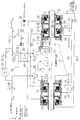
- FIG 1 there is shown a conventional system including gas compressor 1 used for compressing natural gas, for example from a gas production field.
- gas compressor 1 used for compressing natural gas, for example from a gas production field.
- the portion of the compressor located below the axis of its main shaft 2 is indicated diagrammatically, whereas the portion above the shaft axis is depicted in some detail.
- the compressor 1 has a main housing 3, a gas inlet 4, a delivery line 5 delivering production gas at production pressure (low pressure) to the compressor inlet 4, and a gas outlet 6 discharging compressed (high pressure) gas along gas discharge line 7.
- a gas inlet 4 delivering production gas at production pressure (low pressure) to the compressor inlet 4
- a gas outlet 6 discharging compressed (high pressure) gas along gas discharge line 7.
- Within the housing 3 are successive, axially separated, gas compression stages or impellers.
- FIG. 1 are shown, by way of example, three compression stages 1a, 1b, 1c, but it is to be understood that any number of such stages may be used.
- the compressor will have between one and ten gas compression stages.
- the compression stages 1a, 1b, 1c progressively compress the low-pressure inlet gas, for discharge from the compressor as high-pressure gas.
- the compressor comprises a balance drum 8 with associated labyrinth seal 8a, separating the high-pressure region within the compressor housing from a balance chamber 9, which is maintained at the same pressure as the inlet pressure to the compressor.
- a pressure equalization line 10 connects the compressor inlet 4 to the balance chamber 9, as diagrammatically depicted in Figure 1.
- the main shaft is supported at each end by a sealing arrangement which will now be described. Only the sealing arrangement at one end, i.e. that where the balance chamber 9 is located, will be described, but it will be appreciated that the description applies correspondingly to the sealing arrangement at the second end.
- a labyrinth shaft seal 11 is provided adjacent the balance chamber 9, but is not sufficient in itself to provide a sufficiently effective and reliable seal. Accordingly, an additional shaft sealing arrangement is provided by tandem inboard and outboard gas seals 12, 13 respectively.
- Such seals are well known in the art and need not be further described herein.
- the seals may be constructed in accordance with the disclosure of International Patent Applications PCT/IB94/00379, PCT/GB96/00939 or PCT/GB96/00940, all belonging to the present applicants.
- An inlet port 12a of inboard gas seal 12 is supplied with gas by the delivery gas pressure in gas discharge line 7, by way of a branch line from discharge line 7 comprising a common line 14 and a branch section 15.
- the common line 14 also supplies gas to the inboard gas seal at the other end of the compressor in corresponding fashion.
- Each outboard seal 13 has an inlet port 13a which, as shown, is blocked off. Alternatively, no inlet port is provided at all.
- a filter system 16 is incorporated in line 14 for removing solid and liquid particulates from the high-pressure gas flow and thereby cleans the gas before it reaches the tandem gas seals (12, 13).
- the outboard face of labyrinth seal 11 communicates via a small gap between the stationary and moving parts of gas seal 12 with the gas pressure at the port 12a, which is slightly above the pressure (compressor inlet pressure) in the balance chamber 9, so that there is a small flow of gas along this route, past the labyrinth seal 11, between the seal and shaft surface, and into the interior of the compressor.
- the remainder of the gas entering port 12a flows through the inboard gas seal 12 and arrives in a gas chamber 17 between the inboard and outboard seals 12, 13, a proportion of this gas being conveyed from this chamber 17 to a discharge line 18 leading to a flare system, which burns the discharged gas.
- the flare system operates at a pressure slightly above atmospheric pressure, say a few hundred millibars (e.g. 0.2 to 0.3 bar above atmospheric pressure).
- the compressor system also includes various control valves, specifically an automatic on/off valve 20 connected in gas delivery line 5, a further automatic on/off valve 21 connected in gas discharge line 7, and a control valve 22 connected in common line 14.
- the function of control valve 22 is, under normal operation, to reduce the gas discharge pressure in line 7 to a pressure just above that in line 5 and also to reduce the flow rate (and thereby increase the gas residence time in the filter), so as to ensure adequate filtering performance.
- Automatic on/off valves 20, 21 are operated from a central control panel.
- an anti-surge valve 32 and cooler 33 are included in a bypass line 31, connecting delivery line 5 to discharge line 7.
- the anti-surge valve 32 is responsive to the inlet flow through line 5 so as to open when the gas flow falls to a predetermined value, say 70% of nominal flow, below which there would be a risk of compressor operation becoming unstable (surging) due to reverse flow through the compressor, in turn causing shaft vibration.
- a predetermined value say 70% of nominal flow
- the cooler 33 serves to cool the gas passing through connecting line 31 from its high pressure end to its low pressure end, to keep the gas inlet temperature to the compressor at an acceptable level.
- the compressor operates as follows.
- on/off valves 20, 21 are both open and anti-surge valve 32 is closed.
- the compressor 1 compresses the low-pressure inlet gas in its successive stages and delivers high-pressure gas through gas discharge line 7. A proportion of this gas is branched off through common line 14 and solid and liquid particles in the line are removed by filter system 16.
- the gas pressure in common line 14 is then reduced by control valve 22 to a value just slightly above the gas inlet pressure to the compressor. This establishes the sealing pressure (SP) of the inboard gas seal 12.
- SP sealing pressure
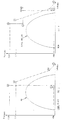
- FIG 2 this is a pressure-enthalpy diagram, from which the operation of the compressor will be understood.
- the sealing pressure of the inboard gas seal 12 is denoted by the value "SP" on the pressure abscissa. Because this sealing pressure is very slightly larger than the inlet pressure maintained in balance chamber 9, there will be a small flow of gas from the outboard side of labyrinth seal 11 to the inboard side, typically 1% of the compressor delivery. The remaining proportion of the gas passes through the inboard gas seal 12 to gas chamber 17, from where a proportion of the gas passes to flare and the remainder flows, via second gas seal 13, to vent, as described above.
- the inlet gas pressure or sealing pressure SP to the gas seal 12 of the gas sealing arrangement is indicated by operating point A, that in the region of the inboard seal 12 communicating with gas chamber 17 being denoted by B and that in the region of the outboard gas seal 13 communicating with the vent line 19 by C.
- operating point A that in the region of the inboard seal 12 communicating with gas chamber 17 being denoted by B
- B that in the region of the outboard gas seal 13 communicating with the vent line 19 by C.
- the reason why the enthalpy of the gas flow increases when passing from operating point A to operating point B and when passing from operating point B to operating point C is that the gas becomes heated due to internal frictional forces acting as the gas passes through the inboard and outboard seals.
- the gas passing through vent line 19 is at atmospheric pressure, ATM.
- valves 20 and 21 are closed first, and then anti-surge valve 32 opens to equalize the supply and delivery pressures and thereby reduce the pressure in gas discharge line 7 to a residual delivery gas pressure, commonly known as the settle out pressure (SOP).
- SOP settle out pressure
- the gas flow through control valve 22 is significantly reduced, which in turn reduces the pressure drop across it to a value approaching zero. Accordingly, the settle out pressure SOP is present as the inlet pressure to inlet port 12a to inboard seal 12 (operating point D in Figure 2).
- Gas flow into seal 12, when the compressor is under SOP, is via two routes, i.e.
- the gas pressure having the settle out pressure at the inlet port 12a falls by a large amount to an intermediate pressure value in the region of inboard seal 12 communicating with gas chamber 17, this intermediate pressure being that of the flare system which is at slightly above atmospheric pressure (operating point E), and by a smaller amount in outboard seal 13 to atmospheric pressure in the region of that seal in communication with vent line 19 (operating point F). Since the operating line D-E, E-F intersects the phase boundary PB and enters the liquid-vapour phase region, condensate will form in the two gas seals 12, 13. This condensate enters the gas sealing regions of the gas seals.
- the present invention seeks to solve this problem by preventing the formation of condensate in the inboard and outboard gas seals of the sealing arrangement.
- the present invention in common with the compressor described with reference to Figure 1, provides a gas compressor having a main housing, a main shaft extending through said housing at one end thereof, a low pressure gas inlet, a high pressure gas outlet, and inboard and outboard tandem gas seals for the main shaft at said one end of the compressor housing, said inboard gas seal having an inlet connected to receive a sealing pressure maintained by the delivery pressure of the compressor.
- the invention is characterized by means operative, when the gas compressor is temporarily stopped and its inlet and outlet pressure are equalized, to provide a residual delivery gas pressure, to connect an inlet of said outboard gas seal to receive the residual delivery gas pressure and to reduce the pressure of a mixture of the gases that have passed through the inboard and outboard seals and further characterized by heating means for raising the temperature of the gas flow, produced by said residual delivery gas pressure, to the outboard gas seal, to prevent formation of condensate or freezing in the inboard and outboard gas seals.
- the inlet of the outboard gas seal is connected via a branch line from a high pressure gas discharge line connected to the compressor outlet, said branch line including a first on-off valve and said heating means being located in thermal communication with said branch line.
- a control valve may be included in the branch line and is set to reduce the gas pressure to a value lower than the residual gas pressure. Providing the reduced gas pressure is high enough such that the gas remains outside its liquid-vapour phase boundary, no condensate can form.
- a second on-off valve is provided in a line leading from a gas chamber, communicating between the inboard and outboard seals, to flare, and a throttle element is connected in parallel with said second on-off valve.
- the second on-off valve is in its open condition during normal operation. However, when the compressor is stopped, this valve is shut off to divert the flow through the throttle element, which serves both to help conserve the residual gas pressure in the high pressure gas discharge line by limiting the gas flow and to maintain elevated pressure in the gas chamber between the two seals, as well as in the regions of the two seals communicating with that chamber.
- the invention also provides a method of operating a gas compressor having a main housing, a main shaft extending through said housing at one end thereof, a low pressure gas inlet, a high pressure gas outlet, and inboard and outboard tandem gas seals for the main shaft at said one end of the compressor housing, wherein, in normal operation of the gas compressor, gas at sealing pressure is supplied by the delivery pressure of the compressor to the inboard gas seal and, when the gas compressor is temporarily stopped and the inlet and outlet pressures are equalized to provide a residual delivery gas pressure, gas supplied by the residual delivery gas pressure of the compressor is introduced into the outboard gas seal under conditions of temperature and pressure such as to prevent formation of condensate or freezing in the inboard and outboard gas seals.
- the gas introduced into the outboard gas seal when the gas compressor is temporarily stopped is heated to raise its temperature.
- the gas pressure may be reduced from its residual delivery gas pressure before it is introduced into the outboard gas seal.
- a gas flow to flare from a gas chamber between the inboard and outboard seals is throttled to maintain elevated gas pressure in said gas chamber.
- a further branch line 25 starts from a point in common line 14 between filter system 16 and control valve 22 and leads to inlet port 13a of each outboard gas seal 13.
- an automatic on/off valve 26 which is closed when the compressor is operating
- a control valve 27 and an electrical heating coil 28.
- Valve 27 and coil 28 can be provided in branch line 25 in either order.
- an automatic on/off valve 29 is connected in discharge line 18 and a throttle element in the form of an orifice plate 30 is connected in parallel with valve 29.
- valves 20, 21 and 29 close and then valves 26, 32 open.
- the residual delivery gas pressure (SOP) in lines 15, 25, represented by operating point D in Figure 4, causes gas to flow in branch lines 15, 25.
- the gas passing through seal 12 (coming from line 15 and past labyrinth seal 11) and into gas chamber 17 is at operating point G.
- the control valve 27 in line 25 reduces the gas pressure from the valve (SOP) by an amount determined by the setting of the control valve, to a lower pressure value.
- the gas is then heated by electrical heating coil 28 to raise its temperature, and the heated gas enters the inlet port 13a of gas seal 13 and flows to gas chamber 17, where its pressure has the value set by control valve 27 (operating point H').
- the flow rate through inlet port 13a is higher than through inlet port 12a, because it passes partly through the outboard seal 13 to vent and partly through the orifice plate 30.
- gas chamber 17 the gas flows from the inboard and outboard seals 12, 13 become mixed.
- the gas mixture in gas chamber 17 is represented in Figure 3 by operating point H.
- the pressure of the gas leaving the gas chamber 17 is then reduced by orifice plate 30 to a pressure slightly above (a few to a few hundred millibars above) atmospheric pressure prevailing in discharge line 18 (operating point I).
- the gas leaving seal 13 and passing to vent at atmospheric pressure is represented by operating point J.
- the function of the orifice plate is to establish the operating point H at a suitable pressure level above atmospheric pressure, such that operating point G is not within the phase envelope PB.
- the size of the orifice in the orifice plate has to be selected to set the gas flow rate through gas chamber 17 such that the heat transfer to the gas seals does not cause the gas in the sealing arrangement to enter its liquid-vapour
Landscapes
- Engineering & Computer Science (AREA)
- Mechanical Engineering (AREA)
- General Engineering & Computer Science (AREA)
- Physics & Mathematics (AREA)
- Thermal Sciences (AREA)
- Structures Of Non-Positive Displacement Pumps (AREA)
- Compressor (AREA)
Priority Applications (8)
| Application Number | Priority Date | Filing Date | Title |
|---|---|---|---|
| EP98403124A EP1008759A1 (de) | 1998-12-10 | 1998-12-10 | Gasverdichter |
| DE69907954T DE69907954T2 (de) | 1998-12-10 | 1999-12-06 | Gasverdichter |
| EP99963394A EP1137887B1 (de) | 1998-12-10 | 1999-12-06 | Gasverdichter |
| PCT/EP1999/009516 WO2000034662A1 (en) | 1998-12-10 | 1999-12-06 | Gas compressor |
| CA002352812A CA2352812A1 (en) | 1998-12-10 | 1999-12-06 | Gas compressor |
| AU19707/00A AU1970700A (en) | 1998-12-10 | 1999-12-06 | Gas compressor |
| JP2000587084A JP2002531775A (ja) | 1998-12-10 | 1999-12-06 | ガス圧縮機 |
| US09/879,871 US6607348B2 (en) | 1998-12-10 | 2001-06-05 | Gas compressor |
Applications Claiming Priority (1)
| Application Number | Priority Date | Filing Date | Title |
|---|---|---|---|
| EP98403124A EP1008759A1 (de) | 1998-12-10 | 1998-12-10 | Gasverdichter |
Publications (1)
| Publication Number | Publication Date |
|---|---|
| EP1008759A1 true EP1008759A1 (de) | 2000-06-14 |
Family
ID=8235587
Family Applications (2)
| Application Number | Title | Priority Date | Filing Date |
|---|---|---|---|
| EP98403124A Withdrawn EP1008759A1 (de) | 1998-12-10 | 1998-12-10 | Gasverdichter |
| EP99963394A Expired - Lifetime EP1137887B1 (de) | 1998-12-10 | 1999-12-06 | Gasverdichter |
Family Applications After (1)
| Application Number | Title | Priority Date | Filing Date |
|---|---|---|---|
| EP99963394A Expired - Lifetime EP1137887B1 (de) | 1998-12-10 | 1999-12-06 | Gasverdichter |
Country Status (7)
| Country | Link |
|---|---|
| US (1) | US6607348B2 (de) |
| EP (2) | EP1008759A1 (de) |
| JP (1) | JP2002531775A (de) |
| AU (1) | AU1970700A (de) |
| CA (1) | CA2352812A1 (de) |
| DE (1) | DE69907954T2 (de) |
| WO (1) | WO2000034662A1 (de) |
Cited By (8)
| Publication number | Priority date | Publication date | Assignee | Title |
|---|---|---|---|---|
| US6708981B2 (en) * | 2000-02-24 | 2004-03-23 | John Crane Uk Limited | Seal assemblies |
| EP1420167A2 (de) * | 2002-11-13 | 2004-05-19 | Nuovo Pignone Holding S.P.A. | Dichtgasumwälzvorrichtung für Gleitringdichtungen eines Kreiselverdichters |
| EP1577561A1 (de) * | 2004-03-19 | 2005-09-21 | MAN Turbomaschinen AG Schweiz | Umwälz- und Heizvorrichtung für einen Rotationskompressor |
| WO2008002148A1 (en) * | 2006-06-30 | 2008-01-03 | Aker Kvaerner Subsea As | Method and apparatus for protection of compressor modules against influx of contaminated gas |
| WO2012018459A3 (en) * | 2010-07-26 | 2012-04-12 | Dresser-Rand Company | Method and system for reducing seal gas consumption and settle-out pressure reduction in high-pressure compression systems |
| WO2012058069A3 (en) * | 2010-10-27 | 2012-07-05 | Dresser-Rand Company | System and method for rapid pressurization of a motor/bearing cooling loop for a hermetically sealed motor/compressor system |
| RU2455530C2 (ru) * | 2008-02-25 | 2012-07-10 | Сименс Акциенгезелльшафт | Компрессорная установка |
| WO2015193269A1 (de) * | 2014-06-18 | 2015-12-23 | Siemens Aktiengesellschaft | Fluidenergiemaschine mit tandem-trockengasdichtung |
Families Citing this family (43)
| Publication number | Priority date | Publication date | Assignee | Title |
|---|---|---|---|---|
| ITMI20021222A1 (it) * | 2002-06-05 | 2003-12-05 | Nuovo Pignone Spa | Sistema di tenuta per compressori centrifughi che eleborano gas letali |
| ITMI20022337A1 (it) * | 2002-11-05 | 2004-05-06 | Nuovo Pignone Spa | Assieme di bilanciamento di spinta assiale per un |
| US8075668B2 (en) | 2005-03-29 | 2011-12-13 | Dresser-Rand Company | Drainage system for compressor separators |
| EP1744131A1 (de) * | 2005-07-15 | 2007-01-17 | Indufil B.V. | Modul für ein Gassystem |
| JP4857766B2 (ja) | 2005-12-28 | 2012-01-18 | 株式会社日立プラントテクノロジー | 遠心圧縮機およびそれに用いるドライガスシールシステム |
| EP2063978B1 (de) | 2006-09-19 | 2014-07-09 | Dresser-Rand Company | Dichtung für drehabscheidertrommel |
| CA2663531C (en) | 2006-09-21 | 2014-05-20 | William C. Maier | Separator drum and compressor impeller assembly |
| WO2008039446A2 (en) | 2006-09-25 | 2008-04-03 | Dresser-Rand Company | Fluid deflector for fluid separator devices |
| BRPI0717090A8 (pt) | 2006-09-25 | 2017-09-12 | Dresser Rand Co | Sistema de montagem de compressor |
| CA2663751C (en) | 2006-09-25 | 2015-01-27 | William C. Maier | Access cover for pressurized connector spool |
| BRPI0717087B1 (pt) | 2006-09-25 | 2018-10-16 | Dresser Rand Co | sistema de carretel conector para conectar um primeiro componente e um segundo componente de um sistema de compressão industrial |
| BRPI0717088B1 (pt) | 2006-09-25 | 2019-10-29 | Dresser Rand Co | sistema de proteção de acoplamento |
| EP2415507A1 (de) | 2006-09-26 | 2012-02-08 | Dresser-Rand Company | Verbesserte statische Flüssigkeitstrennungsvorrichtung |
| JP4975574B2 (ja) * | 2007-09-20 | 2012-07-11 | 三菱重工コンプレッサ株式会社 | 圧縮機およびその運転方法 |
| US8408879B2 (en) | 2008-03-05 | 2013-04-02 | Dresser-Rand Company | Compressor assembly including separator and ejector pump |
| JP4898743B2 (ja) * | 2008-06-09 | 2012-03-21 | 三菱重工業株式会社 | 回転機械のシール構造 |
| US7922218B2 (en) | 2008-06-25 | 2011-04-12 | Dresser-Rand Company | Shear ring casing coupler device |
| US8079805B2 (en) | 2008-06-25 | 2011-12-20 | Dresser-Rand Company | Rotary separator and shaft coupler for compressors |
| US8062400B2 (en) | 2008-06-25 | 2011-11-22 | Dresser-Rand Company | Dual body drum for rotary separators |
| DE102008031980A1 (de) * | 2008-07-07 | 2010-01-21 | Siemens Aktiengesellschaft | Verfahren zum Betrieb einer Maschine mit einer Wellendichtung |
| US8087901B2 (en) | 2009-03-20 | 2012-01-03 | Dresser-Rand Company | Fluid channeling device for back-to-back compressors |
| US8210804B2 (en) | 2009-03-20 | 2012-07-03 | Dresser-Rand Company | Slidable cover for casing access port |
| US8061972B2 (en) | 2009-03-24 | 2011-11-22 | Dresser-Rand Company | High pressure casing access cover |
| US20100253005A1 (en) * | 2009-04-03 | 2010-10-07 | Liarakos Nicholas P | Seal for oil-free rotary displacement compressor |
| BR112012005866B1 (pt) | 2009-09-15 | 2021-01-19 | Dresser-Rand Company | aparelho para a separação de um fluido e método para a separação de um componente de peso específico mais alto de um componente de peso específico mais baixo de um fluido |
| EP2533905B1 (de) | 2010-02-10 | 2018-07-04 | Dresser-Rand Company | Separatorflüssigkeitsbehälter und verfahren dafür |
| IT1399881B1 (it) * | 2010-05-11 | 2013-05-09 | Nuova Pignone S R L | Configurazione di tamburo di bilanciamento per rotori di compressore |
| US8673159B2 (en) | 2010-07-15 | 2014-03-18 | Dresser-Rand Company | Enhanced in-line rotary separator |
| WO2012009159A2 (en) | 2010-07-15 | 2012-01-19 | Dresser-Rand Company | Radial vane pack for rotary separators |
| WO2012012018A2 (en) | 2010-07-20 | 2012-01-26 | Dresser-Rand Company | Combination of expansion and cooling to enhance separation |
| WO2012012143A2 (en) | 2010-07-21 | 2012-01-26 | Dresser-Rand Company | Multiple modular in-line rotary separator bundle |
| WO2012033632A1 (en) | 2010-09-09 | 2012-03-15 | Dresser-Rand Company | Flush-enabled controlled flow drain |
| WO2013109235A2 (en) | 2010-12-30 | 2013-07-25 | Dresser-Rand Company | Method for on-line detection of resistance-to-ground faults in active magnetic bearing systems |
| US8994237B2 (en) | 2010-12-30 | 2015-03-31 | Dresser-Rand Company | Method for on-line detection of liquid and potential for the occurrence of resistance to ground faults in active magnetic bearing systems |
| WO2012138545A2 (en) | 2011-04-08 | 2012-10-11 | Dresser-Rand Company | Circulating dielectric oil cooling system for canned bearings and canned electronics |
| EP2715167B1 (de) | 2011-05-27 | 2017-08-30 | Dresser-Rand Company | Segmentiertes auslauflager für magnetlagersysteme |
| US8851756B2 (en) | 2011-06-29 | 2014-10-07 | Dresser-Rand Company | Whirl inhibiting coast-down bearing for magnetic bearing systems |
| CN102959287B (zh) * | 2011-10-27 | 2015-10-07 | 三菱重工业株式会社 | 干气密封结构 |
| JP5846967B2 (ja) * | 2012-03-02 | 2016-01-20 | 株式会社日立製作所 | 遠心式水蒸気圧縮機およびそれに用いる軸封システム |
| ITCO20120066A1 (it) * | 2012-12-20 | 2014-06-21 | Nuovo Pignone Srl | Metodo per bilanciare la spinta, turbina e motore a turbina |
| CN106286215A (zh) * | 2016-08-31 | 2017-01-04 | 内蒙古汇能煤化工有限公司 | 甲烷化压缩机干气密封系统 |
| CN107269315B (zh) * | 2017-07-31 | 2019-08-09 | 上海齐耀膨胀机有限公司 | 用于低温介质气的螺杆机密封系统及防止密封失效的方法 |
| SG10201912904SA (en) * | 2019-02-18 | 2020-09-29 | Sulzer Management Ag | Process fluid lubricated pump and seawater injection system |
Citations (8)
| Publication number | Priority date | Publication date | Assignee | Title |
|---|---|---|---|---|
| US3420434A (en) | 1966-12-30 | 1969-01-07 | Judson S Swearingen | Rotary compressors and systems employing same using compressor gas as seal gas |
| EP0361844A2 (de) * | 1988-09-30 | 1990-04-04 | Nova Corporation Of Alberta | Gasverdichter mit Trockendichtungen |
| WO1991014853A1 (en) * | 1990-03-20 | 1991-10-03 | Nova Corporation Of Alberta | Control system for regulating the axial loading of a rotor of a fluid machine |
| DE4225642C1 (de) * | 1992-07-02 | 1993-07-29 | Sulzer-Escher Wyss Ag, Zuerich, Ch | |
| US5421593A (en) | 1993-08-05 | 1995-06-06 | Nippon Pillar Packing Co., Ltd. | Shaft seal device |
| WO1996015397A1 (en) | 1994-11-16 | 1996-05-23 | Dresser-Rand Company | A shaft seal |
| WO1996033357A1 (en) | 1995-04-20 | 1996-10-24 | Dresser-Rand Company | A shaft seal |
| WO1996033358A1 (en) | 1995-04-20 | 1996-10-24 | Dresser-Rand Company | A shaft seal |
Family Cites Families (1)
| Publication number | Priority date | Publication date | Assignee | Title |
|---|---|---|---|---|
| US5718560A (en) * | 1995-12-29 | 1998-02-17 | Sulzer Turbo Ag | Turbocompressor for non-ideal process gases |
-
1998
- 1998-12-10 EP EP98403124A patent/EP1008759A1/de not_active Withdrawn
-
1999
- 1999-12-06 EP EP99963394A patent/EP1137887B1/de not_active Expired - Lifetime
- 1999-12-06 WO PCT/EP1999/009516 patent/WO2000034662A1/en active IP Right Grant
- 1999-12-06 AU AU19707/00A patent/AU1970700A/en not_active Abandoned
- 1999-12-06 JP JP2000587084A patent/JP2002531775A/ja not_active Withdrawn
- 1999-12-06 CA CA002352812A patent/CA2352812A1/en not_active Abandoned
- 1999-12-06 DE DE69907954T patent/DE69907954T2/de not_active Expired - Fee Related
-
2001
- 2001-06-05 US US09/879,871 patent/US6607348B2/en not_active Expired - Lifetime
Patent Citations (8)
| Publication number | Priority date | Publication date | Assignee | Title |
|---|---|---|---|---|
| US3420434A (en) | 1966-12-30 | 1969-01-07 | Judson S Swearingen | Rotary compressors and systems employing same using compressor gas as seal gas |
| EP0361844A2 (de) * | 1988-09-30 | 1990-04-04 | Nova Corporation Of Alberta | Gasverdichter mit Trockendichtungen |
| WO1991014853A1 (en) * | 1990-03-20 | 1991-10-03 | Nova Corporation Of Alberta | Control system for regulating the axial loading of a rotor of a fluid machine |
| DE4225642C1 (de) * | 1992-07-02 | 1993-07-29 | Sulzer-Escher Wyss Ag, Zuerich, Ch | |
| US5421593A (en) | 1993-08-05 | 1995-06-06 | Nippon Pillar Packing Co., Ltd. | Shaft seal device |
| WO1996015397A1 (en) | 1994-11-16 | 1996-05-23 | Dresser-Rand Company | A shaft seal |
| WO1996033357A1 (en) | 1995-04-20 | 1996-10-24 | Dresser-Rand Company | A shaft seal |
| WO1996033358A1 (en) | 1995-04-20 | 1996-10-24 | Dresser-Rand Company | A shaft seal |
Cited By (20)
| Publication number | Priority date | Publication date | Assignee | Title |
|---|---|---|---|---|
| US6708981B2 (en) * | 2000-02-24 | 2004-03-23 | John Crane Uk Limited | Seal assemblies |
| EP1420167A2 (de) * | 2002-11-13 | 2004-05-19 | Nuovo Pignone Holding S.P.A. | Dichtgasumwälzvorrichtung für Gleitringdichtungen eines Kreiselverdichters |
| EP1420167A3 (de) * | 2002-11-13 | 2005-01-12 | Nuovo Pignone Holding S.P.A. | Dichtgasumwälzvorrichtung für Gleitringdichtungen eines Kreiselverdichters |
| AU2003261506B2 (en) * | 2002-11-13 | 2009-02-19 | Nuovo Pignone Holding S.P.A. | Device for circulating sealing gas for mechanical dry seals of a centrifugal compressor at times when the machine is stationary and pressurized |
| EP1577561A1 (de) * | 2004-03-19 | 2005-09-21 | MAN Turbomaschinen AG Schweiz | Umwälz- und Heizvorrichtung für einen Rotationskompressor |
| WO2005090793A1 (de) * | 2004-03-19 | 2005-09-29 | Man Turbo Ag Schweiz | Umwälzvorrichtung für einen rotationskompressor, rotationskompressor, und verfahren zum betrieb eines rotationskompressors |
| WO2008002148A1 (en) * | 2006-06-30 | 2008-01-03 | Aker Kvaerner Subsea As | Method and apparatus for protection of compressor modules against influx of contaminated gas |
| NO326735B1 (no) * | 2006-06-30 | 2009-02-09 | Aker Subsea As | Fremgangsmåte og anordning for beskyttelse av kompressormoduler mot uønsket innstrømming av forurenset gass. |
| GB2453093A (en) * | 2006-06-30 | 2009-03-25 | Aker Kvaerner Subsea As | Method and apparatus for protection of compressor modules against influx of contaminated gas |
| GB2453093B (en) * | 2006-06-30 | 2011-04-06 | Aker Kvaerner Subsea As | Method and apparatus for protection of compressor modules against influx of contaminated gas |
| US8221095B2 (en) | 2006-06-30 | 2012-07-17 | Aker Subsea As | Method and apparatus for protection of compressor modules against influx of contaminated gas |
| RU2455530C2 (ru) * | 2008-02-25 | 2012-07-10 | Сименс Акциенгезелльшафт | Компрессорная установка |
| WO2012018459A3 (en) * | 2010-07-26 | 2012-04-12 | Dresser-Rand Company | Method and system for reducing seal gas consumption and settle-out pressure reduction in high-pressure compression systems |
| US8596954B2 (en) | 2010-07-26 | 2013-12-03 | Dresser-Rand Company | Method and system for reducing seal gas consumption and settle-out pressure reduction in high-pressure compression systems |
| WO2012058069A3 (en) * | 2010-10-27 | 2012-07-05 | Dresser-Rand Company | System and method for rapid pressurization of a motor/bearing cooling loop for a hermetically sealed motor/compressor system |
| US9726196B2 (en) | 2010-10-27 | 2017-08-08 | Dresser-Rand Company | System and cooling for rapid pressurization of a motor-bearing cooling loop for a hermetically sealed motor/compressor system |
| WO2015193269A1 (de) * | 2014-06-18 | 2015-12-23 | Siemens Aktiengesellschaft | Fluidenergiemaschine mit tandem-trockengasdichtung |
| CN106460541A (zh) * | 2014-06-18 | 2017-02-22 | 西门子公司 | 具有串联式干气密封件的流能机械 |
| CN106460541B (zh) * | 2014-06-18 | 2018-12-18 | 西门子公司 | 具有串联式干气密封件的流能机械 |
| US10337520B2 (en) | 2014-06-18 | 2019-07-02 | Siemens Aktiengesellschaft | Fluid energy machine having a tandem dry gas seal |
Also Published As
| Publication number | Publication date |
|---|---|
| AU1970700A (en) | 2000-06-26 |
| CA2352812A1 (en) | 2000-06-15 |
| WO2000034662A1 (en) | 2000-06-15 |
| DE69907954T2 (de) | 2004-05-19 |
| JP2002531775A (ja) | 2002-09-24 |
| US20020031437A1 (en) | 2002-03-14 |
| DE69907954D1 (de) | 2003-06-18 |
| US6607348B2 (en) | 2003-08-19 |
| EP1137887B1 (de) | 2003-05-14 |
| EP1137887A1 (de) | 2001-10-04 |
Similar Documents
| Publication | Publication Date | Title |
|---|---|---|
| EP1137887B1 (de) | Gasverdichter | |
| EP0674751B1 (de) | Rotierender schraubenverdichter mit wellenabdichtung | |
| EP0531248B1 (de) | Schmierölrückgewinnung in eine Kreiselverdichterkühlanlage | |
| US6345954B1 (en) | Dry gas seal contamination prevention system | |
| US5611661A (en) | Gas turbine engine with bearing chambers and barrier air chambers | |
| US6708981B2 (en) | Seal assemblies | |
| US5765392A (en) | Screw compressor apparatus for refrigerants with oils soluble in refrigerants | |
| US20120093643A1 (en) | Multistage turbocompressor | |
| US5361592A (en) | Refrigerant conservation system | |
| CN108915810A (zh) | 超临界二氧化碳系统非旋转设备部分的工质置换装置及方法 | |
| JPH01277696A (ja) | オイルフリー・スクリュー圧縮機装置 | |
| JP2004522081A (ja) | 圧縮空気を生成して配給するシステム | |
| US10378536B2 (en) | Air compressor discharge system | |
| CN213064046U (zh) | 一种提高离心压缩机组可靠性的系统 | |
| CN205536637U (zh) | 热泵系统 | |
| RU2211346C1 (ru) | Масляная система газотурбинного двигателя | |
| CN209892411U (zh) | 一种用于超临界二氧化碳的多级气体压缩系统 | |
| CN111706544A (zh) | 一种提高离心压缩机组可靠性的系统及控制方法 | |
| KR20170134802A (ko) | 컴프레서 시스템 | |
| JP2000303990A (ja) | 回転圧縮機の軸封システム | |
| RU2133879C1 (ru) | Система уплотнений турбокомпрессора | |
| JPH01177488A (ja) | 容積型回転式圧縮機 | |
| WO2024104608A1 (en) | A multi-stage in-line compressor system with dry gas seals and method | |
| US20040091371A1 (en) | Pumping device | |
| SU1020684A2 (ru) | Коллектор воздуходувной станции металлургического завода |
Legal Events
| Date | Code | Title | Description |
|---|---|---|---|
| PUAI | Public reference made under article 153(3) epc to a published international application that has entered the european phase |
Free format text: ORIGINAL CODE: 0009012 |
|
| AK | Designated contracting states |
Kind code of ref document: A1 Designated state(s): CH DE FR GB IT LI |
|
| AX | Request for extension of the european patent |
Free format text: AL;LT;LV;MK;RO;SI |
|
| 17P | Request for examination filed |
Effective date: 20001108 |
|
| AKX | Designation fees paid |
Free format text: CH DE FR GB IT LI |
|
| STAA | Information on the status of an ep patent application or granted ep patent |
Free format text: STATUS: THE APPLICATION HAS BEEN WITHDRAWN |
|
| 18W | Application withdrawn |
Withdrawal date: 20010522 |