EP0531248B1 - Schmierölrückgewinnung in eine Kreiselverdichterkühlanlage - Google Patents
Schmierölrückgewinnung in eine Kreiselverdichterkühlanlage Download PDFInfo
- Publication number
- EP0531248B1 EP0531248B1 EP92630079A EP92630079A EP0531248B1 EP 0531248 B1 EP0531248 B1 EP 0531248B1 EP 92630079 A EP92630079 A EP 92630079A EP 92630079 A EP92630079 A EP 92630079A EP 0531248 B1 EP0531248 B1 EP 0531248B1
- Authority
- EP
- European Patent Office
- Prior art keywords
- oil
- cooler
- set forth
- transmission
- ejector
- Prior art date
- Legal status (The legal status is an assumption and is not a legal conclusion. Google has not performed a legal analysis and makes no representation as to the accuracy of the status listed.)
- Expired - Lifetime
Links
Images


Classifications
-
- F—MECHANICAL ENGINEERING; LIGHTING; HEATING; WEAPONS; BLASTING
- F25—REFRIGERATION OR COOLING; COMBINED HEATING AND REFRIGERATION SYSTEMS; HEAT PUMP SYSTEMS; MANUFACTURE OR STORAGE OF ICE; LIQUEFACTION SOLIDIFICATION OF GASES
- F25B—REFRIGERATION MACHINES, PLANTS OR SYSTEMS; COMBINED HEATING AND REFRIGERATION SYSTEMS; HEAT PUMP SYSTEMS
- F25B43/00—Arrangements for separating or purifying gases or liquids; Arrangements for vaporising the residuum of liquid refrigerant, e.g. by heat
- F25B43/02—Arrangements for separating or purifying gases or liquids; Arrangements for vaporising the residuum of liquid refrigerant, e.g. by heat for separating lubricants from the refrigerant
-
- F—MECHANICAL ENGINEERING; LIGHTING; HEATING; WEAPONS; BLASTING
- F04—POSITIVE - DISPLACEMENT MACHINES FOR LIQUIDS; PUMPS FOR LIQUIDS OR ELASTIC FLUIDS
- F04D—NON-POSITIVE-DISPLACEMENT PUMPS
- F04D29/00—Details, component parts, or accessories
- F04D29/06—Lubrication
- F04D29/063—Lubrication specially adapted for elastic fluid pumps
-
- F—MECHANICAL ENGINEERING; LIGHTING; HEATING; WEAPONS; BLASTING
- F25—REFRIGERATION OR COOLING; COMBINED HEATING AND REFRIGERATION SYSTEMS; HEAT PUMP SYSTEMS; MANUFACTURE OR STORAGE OF ICE; LIQUEFACTION SOLIDIFICATION OF GASES
- F25B—REFRIGERATION MACHINES, PLANTS OR SYSTEMS; COMBINED HEATING AND REFRIGERATION SYSTEMS; HEAT PUMP SYSTEMS
- F25B31/00—Compressor arrangements
- F25B31/002—Lubrication
- F25B31/004—Lubrication oil recirculating arrangements
-
- F—MECHANICAL ENGINEERING; LIGHTING; HEATING; WEAPONS; BLASTING
- F25—REFRIGERATION OR COOLING; COMBINED HEATING AND REFRIGERATION SYSTEMS; HEAT PUMP SYSTEMS; MANUFACTURE OR STORAGE OF ICE; LIQUEFACTION SOLIDIFICATION OF GASES
- F25B—REFRIGERATION MACHINES, PLANTS OR SYSTEMS; COMBINED HEATING AND REFRIGERATION SYSTEMS; HEAT PUMP SYSTEMS
- F25B2341/00—Details of ejectors not being used as compression device; Details of flow restrictors or expansion valves
- F25B2341/001—Ejectors not being used as compression device
- F25B2341/0016—Ejectors for creating an oil recirculation
Definitions
- This invention relates generally to centrifugal chiller systems and, more particularly, to a method and apparatus for reclaiming oil from a cooler to the transmission of a centrifugal compressor.
- the most common approach is to provide a stagnant cavity just downstream of the guide vanes in the compressor where oil may accumulate after being carried over with the main flow from the cooler. Some of the oil/refrigerant mixture may also be caused to flow directly from the cooler to the cavity because of the pressure difference between the two.
- An ejector which is preferably driven by a source of gas from a compressor discharge, then functions to pump the oil from the cavity into the transmission of the compressor. This approach works fine for full load and part load operating conditions, but is unsatisfactory during operation in low load conditions. That is, when the guide vanes are closed down to accommodate low load operating conditions, the effectiveness of the ejector is substantially reduced.
- valve means is provided to direct the flow of reclaimed oil along either of two channels, depending on whether the centrifugal compressor is operating under high or low load conditions.
- the reclaimed oil Under low load conditions, when the compressor discharge pressure is too low to provide an adequate flow of reclaimed oil from the suction housing, the reclaimed oil is made to flow directly from the cooler to the transmission of the compressor. Under higher load operating conditions, the valving is switched to provide for the flow of reclaimed oil to and from the suction housing.
- Figure 1 is a schematic illustration of the oil reclaim system in accordance with one embodiment of the invention.
- Figure 2 is a partial front end view of a portion of the compressor with the present invention embodied therein.
- Figure 3 is a bottom view thereof.
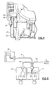
- Figure 4 is a rear end view thereof.
- Figure 5 is a schematic illustration of the sensor and valve portions thereof.
- Figure 6 is a schematic illustration of the oil reclaim system in accordance with another embodiment of the invention.
- FIG. 1 the invention is shown as being incorporated into a chiller type air conditioning system having a cooler 12, a condenser (not shown) and a centrifugal compressor 13. These components are installed in a conventional manner to form a part of a refrigeration circuit which includes an expansion device (not shown) for an introducing refrigerant vapor into the cooler 12, with the centrifugal compressor 13 then compressing the heated vapor coming from the cooler 12 before it passes on to the condenser.
- an expansion device not shown
- the centrifugal compressor 13 is of a conventional type and includes a motor 14, a transmission 16, a compressor discharge section 17, and a suction housing 18.
- the motor 14 drives the compressor impeller through the transmission 16, with the impeller acting to compress the refrigerant passing into the suction housing 18 by way of an inlet 19, after which the compressed refrigerant passes into the compressor discharge section 17 to then flow to the condenser.
- an oil/refrigerant mixture is drawn from the cooler 12, from a point just beneath the top of the cooler bundle, through a filter 20 and along the oil reclaim line 21.
- a check valve 22 is provided to ensure that there is no reverse flow into the cooler 12.
- a "T" connector 23 provides for the flow of oil/refrigerant in either of two lines, the primary line 24 or the secondary line 26, depending on whether the primary solenoid valve 27 or the secondary solenoid valve 28 is open. Those, in turn, will depend on the operating conditions of the centrifugal compressor 13 as will be described hereinafter.
- the solenoid valve 27 Under normal full load and part load operating conditions of the centrifugal compressor 13, the solenoid valve 27 will be open and the solenoid valve 28 will be closed.
- the oil refrigerant mixture then passes along the inlet line 29 to the suction housing 18.
- Fluid communication is then provided from the suction housing 18 by way of suction tube 31, a filter 32, a check valve 33, a line 34, (see also Figure 4), a line 35, an ejector 40, and a ejector discharge line 36, to the transmission 16.
- the ejector 40 is driven by high pressure fluid from the compressor discharge section 17 passing along line 37, a filter 38, and a line 39 to the ejector 40.
- the ejector takes a suction on line 35, and hence to line 21, such that the oil/refrigerant mixture is drawn from the suction housing 18 and pumped into the transmission 16.
- the operation of the solenoid valves 27 and 28 can be controlled by any of various means.
- a preferred approach as shown in Figure 1 is the use of a differential pressure switch 41 which is connected by lines 42 and 43 to the suction housing 18 and the cooler 12, respectively. In normal operation, the pressure at the suction housing 18 and in the cooler 12 is close to being equal. As the load is reduced, however, the pressure in the suction housing 18 is reduced. Thus, when the pressure differential reaches a predetermined limit, the differential pressure switch 41 transmits a signal to the relay 44 to cause the relay 44 to close the solenoid valve 27 and open the solenoid valve 28.
- Typical absolute operating pressures for a system are 5.71 bar (80 psia)in the cooler and 5.64 bar (79 psia)in the suction housing 18 (i.e. downstream of the guide vanes), under full load conditions.
- the typical pressure differential required to switch to the alternative reclaim system would thus be 0.57 to 0.71 bar (8 to 10 psia).
- the position of the guide vanes may be used for this purpose.
- the guide vane actuator 46 which is indicative of the actual position of the guide vanes, passes a representative signal along line 47 to the primary solenoid valve 27, and along line 48 to the secondary solenoid valve 28. Power is supplied to the circuit by way of the line 49 from the power panel.
- the primary solenoid valve 27 is open to pass the reclaimed oil/refrigerant from the cooler to the suction housing 18 and the ejector 40, or the secondary solenoid valve 28 is open to pass the oil/refrigerant mixture directly from the cooler 12 to the ejector 40.
- the primary solenoid valve 27 will be open until the inlet guide vanes are moved to a predetermined threshold position (e.g. 30°) towards the closed position, whereupon a signal will be transmitted to cause the primary solenoid 27 to be closed and the secondary valve 28 to be opened.
- a predetermined threshold position e.g. 30°
- a single 4-way reversing valve as shown at 51 in Figure 6 may be employed. Operation of the 4-way reversing valve 51 is brought about by a pilot valve 52 in response to the above described differential pressure or guide vane position signals as received along line 53.
- Operation of the 4-way reversing valve 51 is as follows. During operation at higher load conditions, the reversing valve 51 interconnects line 21 to line 29 and likewise interconnects line 31 to line 35. During lower load operating conditions, the reversing valve 51 interconnects line 21 directly to line 35, while interconnecting lines 29 and 31 to effectively isolate that portion of the system.
Claims (10)
- Rückgewinnungssystem für Öl für einen radialen Turbokompressor des Typs, der ein Ansauggehäuse (18) mit einem Einlass (29) zum Einfüllen einer Mischung aus Öl und Kühlmittel aus einer Kühlvorrichtung (12) hat, und der einen Hohlraum zum Abscheiden von Öl aus der Mischung, ein Getriebe (16) und eine Saugstrahlpumpe (40), um das abgeschiedene Öl vom Hohlraum zum Getriebe (16) zu pumpen, aufweist, wobei die Verbesserung gekennzeichnet ist durch:
eine erste Ventileinrichtung (27), die fluidleitend zwischen die Kühlvorrichtung (12) und den Einlass (29) geschaltet ist;
eine zweite Ventileinrichtung (28), die fluidleitend zwischen die Kühlvorrichtung (12) und die Saugstrahlpumpe (40) geschaltet ist;
eine Einrichtung (41) zur Bestimmung, wann der Kompressor unter Bedingungen mit kleiner Last betrieben wird; und
eine Steuereinrichtung (44), um auf Befehl die erste Ventileinrichtung (27) zu schliessen und die zweite Ventileinrichtung (28) zu öffnen, so dass die Mischung aus Kühlmittel und Öl direkt von der Kühleinrichtung (12) durch die Saugstrahlpumpe (40) zum Getriebe (16) strömt. - Rückgewinnungssystem für Öl nach Anspruch 1, das zusätzlich in der Lage verstellbare Leitschaufeln enthält und bei dem weiter die Einrichtung zur Bestimmung eine Einrichtung zur Bestimmung der Lage der Leitschaufeln umfasst.
- Rückgewinnungssystem für Öl nach Anspruch 1, dessen Einrichtung zur Bestimmung einen Druckschalter (41) umfasst, der auf den Druck zwischen der Kühlvorrichtung und dem Ansauggehäuse reagiert.
- Rückgewinnungssystem für Öl nach Anspruch 2, bei dem die Lage der Leitschaufeln, die eine Bedingung mit kleiner Last anzeigt, 30° ist.
- Rückgewinnungssystem für Öl nach Anspruch 3, bei dem die Einrichtung (41) zur Bestimmung auf einen Druckunterschied von 0.57-0.71 Bar (8-10 psia) reagiert, um eine Bedingung mit kleiner Last anzuzeigen.
- Rückgewinnungssystem für Öl nach Anspruch 1, bei dem die erste Ventileinrichtung (27) ein elektromagnetisches Ventil umfasst.
- Rückgewinnungssystem für Öl nach Anspruch 1, bei dem die zweite Ventileinrichtung (28) ein elektromagnetisches Ventil umfasst.
- Rückgewinnungssystem für Öl nach Anspruch 1, bei dem die erste und zweite Ventileinrichtung in einem einzelnen Vierwegventil (51) vereinigt sind.
- Verfahren zum Rückgewinnen von Öl in einem radialen Turbokompressor des Typs, der ein Ansauggehäuse (18) mit einem Einlass (29) zum Einfüllen einer Mischung aus Öl und Kühlmittel von einer Kühlvorrichtung (12) hat, und der einen Hohlraum zum Abscheiden von Öl aus der Mischung, ein Getriebe (16) und eine Saugstrahlpumpe (40), um das abgeschiedene Öl vom Hohlraum zum Getriebe (16) zu pumpen, aufweist, gekennzeichnet durch die Schritte:
zu bestimmen, wann der Kompressor unter Bedingungen mit kleiner Last betrieben wird; und
auf Befehl den Fluss der Öl/Kühlmittel Mischung direkt von der Kühleinrichtung (12) durch die Saugstrahlpumpe (40) zum Getriebe (16) zu leiten. - Verfahren zum Rückgewinnen von Öl nach Anspruch 9, welches den zusätzlichen Schritt umfasst, auf Befehl den Fluss der Öl/Kühlmittel Mischung von der Kühlvorrichtung (12) zum Einlass (29) zu verhindern.
Applications Claiming Priority (2)
| Application Number | Priority Date | Filing Date | Title |
|---|---|---|---|
| US07/753,588 US5165248A (en) | 1991-09-03 | 1991-09-03 | Oil reclaim in a centrifugal chiller system |
| US753588 | 1991-09-03 |
Publications (2)
| Publication Number | Publication Date |
|---|---|
| EP0531248A1 EP0531248A1 (de) | 1993-03-10 |
| EP0531248B1 true EP0531248B1 (de) | 1995-10-18 |
Family
ID=25031300
Family Applications (1)
| Application Number | Title | Priority Date | Filing Date |
|---|---|---|---|
| EP92630079A Expired - Lifetime EP0531248B1 (de) | 1991-09-03 | 1992-09-02 | Schmierölrückgewinnung in eine Kreiselverdichterkühlanlage |
Country Status (10)
| Country | Link |
|---|---|
| US (1) | US5165248A (de) |
| EP (1) | EP0531248B1 (de) |
| JP (1) | JPH0827085B2 (de) |
| KR (1) | KR960009344B1 (de) |
| AU (1) | AU650363B2 (de) |
| BR (1) | BR9203434A (de) |
| DE (1) | DE69205534T2 (de) |
| ES (1) | ES2080472T3 (de) |
| MX (1) | MX9205026A (de) |
| TW (1) | TW206276B (de) |
Families Citing this family (27)
| Publication number | Priority date | Publication date | Assignee | Title |
|---|---|---|---|---|
| JP2653334B2 (ja) * | 1993-01-26 | 1997-09-17 | 株式会社日立製作所 | 圧縮式冷凍機 |
| US5361887A (en) * | 1994-03-14 | 1994-11-08 | Otis Elevator Company | Apparatus for detecting an irregularity in the frequency of steps passing a particular point within a passenger conveying device |
| US5664589A (en) * | 1995-08-07 | 1997-09-09 | Affect, Inc. | Hair accessory device made of vinyl plastisol |
| US5675978A (en) * | 1996-11-26 | 1997-10-14 | American Standard Inc. | Oil management apparatus for a refrigeration chiller |
| US5761914A (en) * | 1997-02-18 | 1998-06-09 | American Standard Inc. | Oil return from evaporator to compressor in a refrigeration system |
| US5875640A (en) * | 1997-10-10 | 1999-03-02 | Hill; Herbert L. | Multi-story air conditioning system with oil return means |
| US6065297A (en) * | 1998-10-09 | 2000-05-23 | American Standard Inc. | Liquid chiller with enhanced motor cooling and lubrication |
| US6170286B1 (en) | 1999-07-09 | 2001-01-09 | American Standard Inc. | Oil return from refrigeration system evaporator using hot oil as motive force |
| US6216474B1 (en) * | 1999-09-27 | 2001-04-17 | Carrier Corporation | Part load performance of variable speed screw compressor |
| US6182467B1 (en) * | 1999-09-27 | 2001-02-06 | Carrier Corporation | Lubrication system for screw compressors using an oil still |
| US6341492B1 (en) | 2000-05-24 | 2002-01-29 | American Standard International Inc. | Oil return from chiller evaporator |
| KR100471515B1 (ko) * | 2000-07-13 | 2005-02-21 | 미츠비시 쥬고교 가부시키가이샤 | 냉동기 |
| US20020068185A1 (en) * | 2000-12-06 | 2002-06-06 | Jehuda Greener | Sublimate elimination in dyed polyester films by use of barrier layers |
| US6484517B2 (en) * | 2001-02-27 | 2002-11-26 | Mikhail Levitin | Compressor oil pressure control method and unit |
| US7272953B2 (en) * | 2002-01-08 | 2007-09-25 | Masterson James A | Method and apparatus for separating and neutralizing ammonia |
| US6755029B2 (en) | 2002-01-08 | 2004-06-29 | Marvin Ralph Bertrand, Jr. | Ammonia separator and neutralizer |
| US20040177644A1 (en) * | 2002-01-08 | 2004-09-16 | Masterson James A. | Method and apparatus for separating and neutralizing ammonia |
| CN102767540B (zh) * | 2012-08-10 | 2015-04-15 | 三一能源重工有限公司 | 气体冷却器及压缩机 |
| CN105143787B (zh) * | 2013-03-25 | 2018-04-17 | 开利公司 | 压缩机轴承冷却 |
| US10228168B2 (en) | 2013-03-25 | 2019-03-12 | Carrier Corporation | Compressor bearing cooling |
| JP6096551B2 (ja) * | 2013-03-26 | 2017-03-15 | 荏原冷熱システム株式会社 | ターボ冷凍機 |
| CN105164476A (zh) | 2013-05-02 | 2015-12-16 | 开利公司 | 经由净化单元实现的压缩机轴承冷却 |
| BR102017009824B1 (pt) * | 2017-05-10 | 2023-12-19 | Fmc Technologies Do Brasil Ltda | Sistema para circulação de gás em espaços anulares de máquinas rotativas |
| JP7353275B2 (ja) * | 2017-09-25 | 2023-09-29 | ジョンソン コントロールズ テクノロジー カンパニー | 2段階の油原動力エダクタシステム |
| CN110685952B (zh) * | 2019-09-26 | 2021-11-26 | 沈阳鼓风机集团安装检修配件有限公司 | 润滑油系统、压缩机的失稳调节方法 |
| US11187185B1 (en) * | 2021-04-05 | 2021-11-30 | Cummins Inc. | Waste heat recovery lube oil management |
| DE102021118253B4 (de) | 2021-07-14 | 2023-02-02 | Man Energy Solutions Se | Strömungsmaschinenanordnung |
Family Cites Families (7)
| Publication number | Priority date | Publication date | Assignee | Title |
|---|---|---|---|---|
| CH156330A (de) * | 1928-10-18 | 1932-07-31 | Sulzer Ag | Einrichtung zum Rückführen von Öl aus dem Verdampfer in den Kompressor von Kältemaschinen. |
| US3263435A (en) * | 1963-09-26 | 1966-08-02 | Carrier Corp | Lubricant separation and recovery system |
| US4187695A (en) * | 1978-11-07 | 1980-02-12 | Virginia Chemicals Inc. | Air-conditioning system having recirculating and flow-control means |
| US4213307A (en) * | 1978-11-13 | 1980-07-22 | Westinghouse Electric Corp. | Oil separation and return system for centrifugal refrigerant compressors |
| US4478050A (en) * | 1982-11-19 | 1984-10-23 | Hussmann Corporation | Oil separation for refrigeration system |
| JPH0697122B2 (ja) * | 1985-02-06 | 1994-11-30 | 株式会社荏原製作所 | ターボ冷凍機 |
| US4938664A (en) * | 1989-11-13 | 1990-07-03 | Carrier Corporation | Oil reclaim system |
-
1991
- 1991-09-03 US US07/753,588 patent/US5165248A/en not_active Expired - Fee Related
-
1992
- 1992-08-28 TW TW081106796A patent/TW206276B/zh active
- 1992-09-01 AU AU22011/92A patent/AU650363B2/en not_active Ceased
- 1992-09-02 KR KR92015896A patent/KR960009344B1/ko not_active IP Right Cessation
- 1992-09-02 BR BR929203434A patent/BR9203434A/pt not_active IP Right Cessation
- 1992-09-02 MX MX9205026A patent/MX9205026A/es not_active IP Right Cessation
- 1992-09-02 EP EP92630079A patent/EP0531248B1/de not_active Expired - Lifetime
- 1992-09-02 ES ES92630079T patent/ES2080472T3/es not_active Expired - Lifetime
- 1992-09-02 DE DE69205534T patent/DE69205534T2/de not_active Expired - Fee Related
- 1992-09-03 JP JP4235029A patent/JPH0827085B2/ja not_active Expired - Lifetime
Also Published As
| Publication number | Publication date |
|---|---|
| US5165248A (en) | 1992-11-24 |
| TW206276B (de) | 1993-05-21 |
| KR960009344B1 (en) | 1996-07-18 |
| ES2080472T3 (es) | 1996-02-01 |
| JPH05223366A (ja) | 1993-08-31 |
| MX9205026A (es) | 1993-04-01 |
| AU2201192A (en) | 1993-03-11 |
| DE69205534D1 (de) | 1995-11-23 |
| KR930006410A (ko) | 1993-04-21 |
| DE69205534T2 (de) | 1996-03-21 |
| AU650363B2 (en) | 1994-06-16 |
| BR9203434A (pt) | 1993-04-06 |
| EP0531248A1 (de) | 1993-03-10 |
| JPH0827085B2 (ja) | 1996-03-21 |
Similar Documents
| Publication | Publication Date | Title |
|---|---|---|
| EP0531248B1 (de) | Schmierölrückgewinnung in eine Kreiselverdichterkühlanlage | |
| US4335582A (en) | Unloading control system for helical screw compressor refrigeration system | |
| USRE42966E1 (en) | Tandem compressors with discharge valve on connecting lines | |
| EP1143209B1 (de) | Kältevorrichtung | |
| EP1137887B1 (de) | Gasverdichter | |
| AU2005280900B2 (en) | Refrigeration apparatus | |
| EP0921364A2 (de) | Pulsierender Durchfluss zur Leistungsregelung | |
| KR100834203B1 (ko) | 압축기, 냉매 사이클 및 압축기 제어 방법 | |
| CA2135870C (en) | Liquid pressure amplification with bypass | |
| US5182919A (en) | Oil recovery system for closed type centrifugal refrigerating machine | |
| US4861246A (en) | Injected compressor with liquid switch | |
| EP1065455B1 (de) | Ölabscheiderkreislauf verwendende Heissgasverdichternebenleitung | |
| JPH07120086A (ja) | ヒートポンプ | |
| JP3143142B2 (ja) | 冷凍装置 | |
| JP2757689B2 (ja) | 冷凍装置 | |
| US4890461A (en) | Hermetic or semi-hermetic refrigeration motor-compressor unit | |
| JP2867794B2 (ja) | 暖冷房機 | |
| JP3148403B2 (ja) | 空気調和装置 | |
| JPH01177488A (ja) | 容積型回転式圧縮機 | |
| CN117570532A (zh) | 空调系统 | |
| JPH0914803A (ja) | セパレート形ヒートポンプ | |
| JPH062963A (ja) | 空気調和機 | |
| JPH07294072A (ja) | 冷凍サイクルの圧力検出装置 | |
| JPH01219450A (ja) | ヒートポンプ式冷却装置 | |
| JPS5914698B2 (ja) | 空気調和機の冷媒抜き運転制御方法 |
Legal Events
| Date | Code | Title | Description |
|---|---|---|---|
| PUAI | Public reference made under article 153(3) epc to a published international application that has entered the european phase |
Free format text: ORIGINAL CODE: 0009012 |
|
| AK | Designated contracting states |
Kind code of ref document: A1 Designated state(s): CH DE ES FR GB IT LI NL SE |
|
| 17P | Request for examination filed |
Effective date: 19930903 |
|
| 17Q | First examination report despatched |
Effective date: 19950113 |
|
| GRAA | (expected) grant |
Free format text: ORIGINAL CODE: 0009210 |
|
| AK | Designated contracting states |
Kind code of ref document: B1 Designated state(s): CH DE ES FR GB IT LI NL SE |
|
| REF | Corresponds to: |
Ref document number: 69205534 Country of ref document: DE Date of ref document: 19951123 |
|
| ET | Fr: translation filed | ||
| ITF | It: translation for a ep patent filed |
Owner name: UFFICIO BREVETTI RICCARDI & C. |
|
| REG | Reference to a national code |
Ref country code: ES Ref legal event code: FG2A Ref document number: 2080472 Country of ref document: ES Kind code of ref document: T3 |
|
| PLBE | No opposition filed within time limit |
Free format text: ORIGINAL CODE: 0009261 |
|
| STAA | Information on the status of an ep patent application or granted ep patent |
Free format text: STATUS: NO OPPOSITION FILED WITHIN TIME LIMIT |
|
| 26N | No opposition filed | ||
| PGFP | Annual fee paid to national office [announced via postgrant information from national office to epo] |
Ref country code: FR Payment date: 19990807 Year of fee payment: 8 |
|
| PGFP | Annual fee paid to national office [announced via postgrant information from national office to epo] |
Ref country code: CH Payment date: 19990813 Year of fee payment: 8 |
|
| PGFP | Annual fee paid to national office [announced via postgrant information from national office to epo] |
Ref country code: SE Payment date: 19990816 Year of fee payment: 8 |
|
| PGFP | Annual fee paid to national office [announced via postgrant information from national office to epo] |
Ref country code: GB Payment date: 19990818 Year of fee payment: 8 |
|
| PGFP | Annual fee paid to national office [announced via postgrant information from national office to epo] |
Ref country code: NL Payment date: 19990819 Year of fee payment: 8 |
|
| PGFP | Annual fee paid to national office [announced via postgrant information from national office to epo] |
Ref country code: DE Payment date: 19990825 Year of fee payment: 8 |
|
| PGFP | Annual fee paid to national office [announced via postgrant information from national office to epo] |
Ref country code: ES Payment date: 19990908 Year of fee payment: 8 |
|
| PG25 | Lapsed in a contracting state [announced via postgrant information from national office to epo] |
Ref country code: GB Free format text: LAPSE BECAUSE OF NON-PAYMENT OF DUE FEES Effective date: 20000902 |
|
| PG25 | Lapsed in a contracting state [announced via postgrant information from national office to epo] |
Ref country code: ES Free format text: LAPSE BECAUSE OF NON-PAYMENT OF DUE FEES Effective date: 20000903 |
|
| PG25 | Lapsed in a contracting state [announced via postgrant information from national office to epo] |
Ref country code: SE Free format text: THE PATENT HAS BEEN ANNULLED BY A DECISION OF A NATIONAL AUTHORITY Effective date: 20000929 |
|
| PG25 | Lapsed in a contracting state [announced via postgrant information from national office to epo] |
Ref country code: LI Free format text: LAPSE BECAUSE OF NON-PAYMENT OF DUE FEES Effective date: 20000930 Ref country code: CH Free format text: LAPSE BECAUSE OF NON-PAYMENT OF DUE FEES Effective date: 20000930 |
|
| PG25 | Lapsed in a contracting state [announced via postgrant information from national office to epo] |
Ref country code: NL Free format text: LAPSE BECAUSE OF NON-PAYMENT OF DUE FEES Effective date: 20010401 |
|
| GBPC | Gb: european patent ceased through non-payment of renewal fee |
Effective date: 20000902 |
|
| REG | Reference to a national code |
Ref country code: CH Ref legal event code: PL |
|
| EUG | Se: european patent has lapsed |
Ref document number: 92630079.9 |
|
| PG25 | Lapsed in a contracting state [announced via postgrant information from national office to epo] |
Ref country code: FR Free format text: LAPSE BECAUSE OF NON-PAYMENT OF DUE FEES Effective date: 20010531 |
|
| NLV4 | Nl: lapsed or anulled due to non-payment of the annual fee |
Effective date: 20010401 |
|
| PG25 | Lapsed in a contracting state [announced via postgrant information from national office to epo] |
Ref country code: DE Free format text: LAPSE BECAUSE OF NON-PAYMENT OF DUE FEES Effective date: 20010601 |
|
| REG | Reference to a national code |
Ref country code: FR Ref legal event code: ST |
|
| REG | Reference to a national code |
Ref country code: ES Ref legal event code: FD2A Effective date: 20011011 |
|
| PG25 | Lapsed in a contracting state [announced via postgrant information from national office to epo] |
Ref country code: IT Free format text: LAPSE BECAUSE OF NON-PAYMENT OF DUE FEES;WARNING: LAPSES OF ITALIAN PATENTS WITH EFFECTIVE DATE BEFORE 2007 MAY HAVE OCCURRED AT ANY TIME BEFORE 2007. THE CORRECT EFFECTIVE DATE MAY BE DIFFERENT FROM THE ONE RECORDED. Effective date: 20050902 |